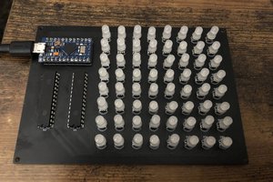
Connect the anode of each LED to digital pins eight, nine and ten (via a 220-ohm resistor). Connect the cathodes to the Arduino’s ground.
Design a Code for Arduino Traffic Light
Start by assigning variables so that you can address the lights by name rather than a number.
Next, add the setup function, where you’ll configure the red, yellow and green LEDs to be outputs. As you have created variables to represent the pin numbers, you can mention to the pins by name instead.
The pinMode function configures the Arduino to use a given pin as an output. Now for the actual logic of the traffic light. Below is the code that you need.
Upload the code to your Arduino and run (make sure to select the correct board and port from the Tools > Board and Tools > Port menus).
The final outcome should have working traffic light that changes every 15 seconds.
IoT Training will help you to implement your own ideas and to build a Customized IoT solutions over several challenges.
 hIOTron
 tehaxor69
 Songkord Thirachai
 vishal soni