Close
0%
0%

2019 Hackaday Superconference Badge

FPGA Running RISC-V Core in a Game Boy form factor

Similar projects worth following
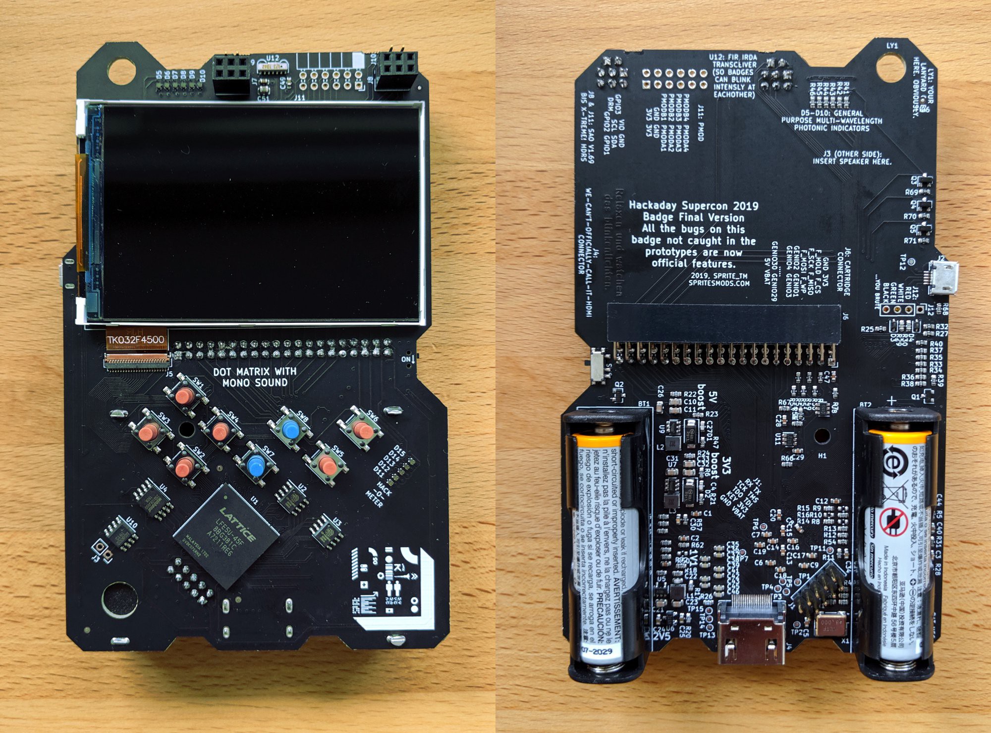
The 2019 Hackaday Superconference badge is based on an ECP5 FPGA with 45k LUTs. It adopts a Game Boy form factor, with eight buttons for user input and a color LCD screen. Apps can be written in C and copied to the badge via a USB mass storage arrangement. There is also a 40-pin cartridge adapter on the back of the badge and the prototyping cartridges have flash memory to store their own apps which can be loaded when the cartridge is inserted.

Jeroen Domburg (aka Sprite_TM) is the hardware and software designer for this badge. He began working on the concept in January of 2019 and the production run of over 500 badges was completed about three weeks prior to the Hackaday Superconference

The firmware and software efforts continue, with a large badge team jumping in to help test and stabilize the FPGA design, to build up workshops around the badge that teach FPGA concepts, and to write the games and apps that come with the stock firmware.

Please Install the Toolchain Before Arriving at Supercon!

You can be up and running very quickly once you get the hardware if you already have the toolchain installed. Sean Cross put together packages for Linux, Mac, and Windows that just need to be unpacked and added to the path of your OS. This includes the open source tools you need to synthesize bitstreams for the FPGA and to compile C code to run on the RISC-V core. See his repo for more information:

https://github.com/xobs/ecp5-toolchain

Main Code Repository:

https://github.com/Spritetm/hadbadge2019_fpgasoc/

Hardware Repository:

https://github.com/Spritetm/hadbadge2019_pcb

Documentation is a Work In Progress.

While you don't need to program the FPGA directly, you might want to.  If so:

http://bit.ly/fpga_badge_workshop

and not as complete, but still fun:

https://github.com/hexagon5un/hackaday_supercon_2019_logic_noise_FPGA_workshop

bootloader.svf

Bootloader for step 1: uploaded via JTAG to RAM.

svf - 581.38 kB - 11/19/2019 at 00:04

Download

bootloader.bit

Bootloader for step 2: once up and running in RAM, upload via USB to flash memory storage.

bit - 272.91 kB - 11/19/2019 at 00:04

Download

  • Quickstart Information

    Lutetium11/04/2019 at 05:51 0 comments

    Items you'll find useful to bring for badge hacking:

    • Required:
      • Laptop computer (Linux, Mac, or Windows)
      • MicroUSB cable
    • Suggested:
      • USB-to-Serial cable (printf is your friend)
      • Replacement AA Batteries. Although we will have extras on hand, this badge is power hungry and avid badge hackers may want to have a few extra sets on hand. NOTE: it is possible to power the badge through the JTAG header but you MUST remove the batteries before doing so
      • PMOD hardware if you have it. The badge has one PMOD footprint and further expansion is available via the 40-pin cartridge

    Getting Your Programs Onto the Badge

    • The badge has a bootloader that allows you to flash your bitstreams to the FPGA via the USB port
    • Badge will enumerate as mass storage. C programs can be copied via this method and will appear on the badge app menu

  • Hardware Overview

    Lutetium11/04/2019 at 05:51 0 comments

    • Lattice LFE5U-45F FPGA is an ECP5 with 45k LUTs
    • 2x  Lyontek LY68L6400 64 Mbit SRAM chips
    • Winbond W25Q128JVSIQ 128 Mbit NOR flash chip
    • 480x320 Color LCD
    • Mono-audio (solder the speakers available in the badge hacking area to J3)
    • 8 user buttons
    • 40-pin cartidge slot
      • Cartridges include flash chips that will be automatically loaded when plugged in
    • MicroUSB port
    • HDMI port
    • 2x SAO v1.69bis X-treme! headers
    • 1x PMOD footprint (solder the headers available in the badge hacking area)
      • It appears the silkscreen numbering for the I/O pins on this footprint is backward. More information on this soon to come.
    • IRDA module

    Accessing Hardware from Userspace

    The most comprehensive and up-to-date documentation on hardware registers is found in the mach_defines.h file. Here is the cartridge I/O info from that file:

    /** General I/O input register. Bits 29-0 reflect the values of the corresponding lines on the cartridge I/O connector. */
    #define MISC_GENIO_IN_REG (17*4)
    /** General I/O output register. Bits 29-0 set the values of the cartridge lines that are selected as outputs. */
    #define MISC_GENIO_OUT_REG (18*4)
    /** General I/O output enable registers. Set 1 to any of the bits 29-0 to make the corresponding line into an output. */
    #define MISC_GENIO_OE_REG (19*4)
    /** Write 1 to set register. Any write of 1 will set the corresponding bit in MISC_GENIO_OUT_REG to 1. */
    #define MISC_GENIO_W2S_REG (20*4)
    /** Write 1 to clear register. Any write of 1 will set the corresponding bit in MISC_GENIO_OUT_REG to 0. */
    #define MISC_GENIO_W2C_REG (21*4)
    /** Extended I/O input register. The bits here reflect the values of the corresponding lines on the cartridge I/O connector:
       (ToDo: insert mapping here)
       Bit 31 reflects the status of the input-only USB VDET line, which is high when a +5V voltage is on the USB VBUS line.
        */

    Cartridges

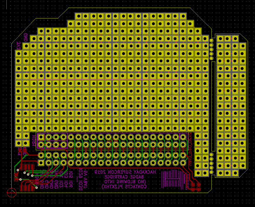
    You will find the cartridge specification here: https://github.com/Spritetm/hadbadge2019_protoboard

    For ease of use, here are images of the board and schematic:

  • Hardware Peripherals for C Programs

    Lutetium11/04/2019 at 05:50 0 comments

    The most comprehensive information on hardware peripherals available to C programs is found in the through comments of the mach_defines.h file of soc/ipl/gloss

    Buttons

    Buttons may be read from a register; the bits in this register go high when the corresponding button is pressed. Button names begin BUTTON_ and end with: UP, DOWN, LEFT, RIGHT, A, B, SELECT, START.

    if ((MISC_REG(MISC_BTN_REG) & BUTTON_RIGHT)) {
        //Do something when right button is pressed.
    }

    Upcounting Timer

    A 60 Hz upcounting timer is available. Higher resolution timers are in the works too. Implement this function to easily read this counter:

    uint32_t counter60hz(void) {
        return GFX_REG(GFX_VBLCTR_REG);
    }

    Additional time and delay utilities are available from the badge time module.

    #include "badgetime.h"     

    Following example set by Arduino, badge time provides a way to retrieve a 32-bit milliseconds count and a way to delay a given number of milliseconds.

    uint32_t now = millis(); // Number of milliseconds since badge power-up.
    
    delay(1000); // Wait one second

    In addition to delay, badge time also provides convenience functions to perform several other popular types of wait. While waiting, these functions will service system background tasks.

    wait_for_button_release(); // Returns once user releases all buttons
    
    wait_for_button_press(BUTTON_RIGHT); // Returns when user presses given button(s)
    
    while (doing something on every frame) {
        uint32_t current_frame = GFX_REG(GFX_VBLCTR_REG);
        // Do what we need to do
        wait_for_next_frame(current_frame); // Service background tasks until next frame needs to be drawn.
    }


     Apps with a tight loop without wait would need to periodically call delay with count of zero to ensure the background tasks are not starved.

    delay(0); // Service background tasks and return as soon as possible

    Random Number Source

    Hardware random number generator can be read via this register:

    MISC_REG(MISC_RNG_REG)

    LEDs

    LED control is provides by this register for most of the functionality for most of the LEDs on the badge. Note that some LEDs can't initially be accessed by software.

    MISC_REG(MISC_LED_REG)=0xF;

  • Graphics Engine Overview for C Programs

    Lutetium10/22/2019 at 13:38 0 comments

    A tile-based graphics engine containing several layers allows for complex manipulations. The most comprehensive information on how this system works is found in the through comments of the mach_defines.h file of soc/ipl/gloss

    Layers from Top to Bottom:

    • Sprite layer
    • Tile layer B
    • Tile layer A
    • Background Layer

    Tileset Details:

    The graphics engine is based on tile sets that are 256x512px in size, containing 16x16 pixel tiles which are indexed left-to-right beginning at the top. Tilesets are limited to a 16-bit color palette.

    Writing to Tile Layers:

    Each tile layer is 64x64 tiles in size, although the screen is 30x20 tiles in size. When a tile layer is enabled, any changes to that layer will be immediately viewable.

    Moving Tile Layers:

    As noted, tile layers are larger than the screen. These can be offset. Tile layers wrap around the screen so by filling all 64 slots and then offsetting the layer in that direction you effectively create infinite scrolling.

    Scaling and Distorting Tile Layers:

    More to come. See main.c of the IPL for working examples.

    Working with the Sprite Layer:

    The sprite layer is not yet fully available. See main.c in IPL and in the Flappy app for some working examples.

  • FPGA Programming Information

    Lutetium10/22/2019 at 13:38 0 comments

    This documentation is a work in progress.

  • Audio Subsystem

    Lutetium10/22/2019 at 13:38 1 comment

    The audio is totally FPGA. There is a digital output pin, run through an RC lowpass filter, that feeds an amplifier.  Your mission, should you choose to accept it: solder a speaker on to pins J3 on the lower lefthand side of the front.  (We'll bring the soldering irons and speakers. Or you could go with a pin-header.)

    The rest is done in gateware.  There is a 14-bit, 24 MHz sigma-delta DAC with a few mixers that feed into it.  For direct PCM/sample output, you simply write samples to memory and they get played. 

    But there's also a full-blown twelve-voice polyphonic synthesizer on board, vaguely inspired by the C64's SID chip, but with a lot more going on. Each voice has configurable attack and release rates, and is capable of running by itself for a predetermined duration once triggered. The result?  You tell a voice to play for so long at this pitch and it happens automagically. Your software can get back to work.

    Naturally, all of this is implemented in "hardware" inside the FPGA itself, so if you want to add some exotic features, just get hacking.

  • ecp5 Toolchain Install

    Lutetium10/22/2019 at 13:36 0 comments

    For Mac OSX (not tested on Catalina):

    These are ecp5 toolchain instructions for Mac OSX and above.

    This has been tested with High Sierra, and has not been tested with Catalina

    Go to the apple symbol in the top left >> About this Mac to check what version OS you have.

    Go here: https://github.com/xobs/ecp5-toolchain/releases/latest and grab the toolchain for your OS. 

    The badge uses a DFU bootloader by @Sylvain Munaut . You need dfu-util to interface with this; a binary is provided in the toolchain archive you just downloaded.

    You’ll need to add the ecp5 toolchain to your path. This is how.

    Test that your toolchain is working by putting yosys and then nextpnr-ecp5 in the terminal prompt. 

    If these work, your toolchain is installed. 

    Troubleshooting

    Check your path.

    For Debian

    Coming Soon.

    For Windows 10

    Coming Soon.

  • Restore DFU Bootloader

    Lutetium10/22/2019 at 13:36 0 comments

    Procedure to repair a damaged badge DFU (Device Firmware Update) partition.

    Parts needed:

    • OpenOCD compatible JTAG adapter hardware. (Output shown below were from using a Segger J-Link.)
    • Computer with OpenOCD installed.
    • Micro USB cable for connecting computer to badge.
    • Computer with DFU utility installed. (Debian-based Linux distros can install with `sudo apt install dfu-util`)
    • Hackaday Superconference 2019 Badge.
    • Bootloader files "bootloader.svf" and "bootloader.bit" from the "Files" section of this project.

    Procedure:

    • Turn on badge while holding SW7 and SW8.
    • Nothing visible on LCD. (If you see DFU screen, damaged DFU is probably not the problem, but you can go through this procedure anyway if you choose.)
    • Verify computer attached via micro USB port does not see USB device. (If it does, again damaged DFU is probably not the problem.)
    • Connect to badge via JTAG with OpenOCD. (If it does not connect, there are problems beyond DFU.)
    Info : JTAG tap: ecp5.tap tap/device found: 0x41112043 (mfg: 0x021 (Lattice Semi.), part: 0x1112, ver: 0x4)


    • Initialize OpenOCD, upload "bootloader.svf" to badge RAM, then exit.
    > init
    > svf bootloader.svf
    
    [... lots of text trimmed ...]
    
    svf file programmed successfully for 58 commands with 0 errors
    > exit
    •  You should see DFU screen at this point, but it is only running from RAM and will disappear if the badge is restarted.
    • But we should now see a DFU device over the micro USB port, and can use it to write bootloader to flash memory storage.
    • Use "dfu-util -l" to list all available locations Look for "Bootloader" and note its number (in this example, 5)
    dfu-util 0.9
    
    Copyright 2005-2009 Weston Schmidt, Harald Welte and OpenMoko Inc.
    Copyright 2010-2016 Tormod Volden and Stefan Schmidt
    This program is Free Software and has ABSOLUTELY NO WARRANTY
    Please report bugs to http://sourceforge.net/p/dfu-util/tickets/
    
    Found DFU: [1d50:614b] ver=0005, devnum=62, cfg=1, intf=0, path="1-2", alt=5, name="Bootloader", serial="e4692895a72b5c23"
    Found DFU: [1d50:614b] ver=0005, devnum=62, cfg=1, intf=0, path="1-2", alt=4, name="Cartridge main FS region", serial="e4692895a72b5c23"
    Found DFU: [1d50:614b] ver=0005, devnum=62, cfg=1, intf=0, path="1-2", alt=3, name="Cartridge IPL region", serial="e4692895a72b5c23"
    Found DFU: [1d50:614b] ver=0005, devnum=62, cfg=1, intf=0, path="1-2", alt=2, name="Cartridge ECP5 bitstream", serial="e4692895a72b5c23"
    Found DFU: [1d50:614b] ver=0005, devnum=62, cfg=1, intf=0, path="1-2", alt=1, name="RISC-V firmware (IPL)", serial="e4692895a72b5c23"
    Found DFU: [1d50:614b] ver=0005, devnum=62, cfg=1, intf=0, path="1-2", alt=0, name="ECP5 bitstream (SoC)", serial="e4692895a72b5c23"
    
    •  Upload 'bootloader.bit' to that location specified via the "-a" parameter.
    dfu-util -d 1d50:614a,1d50:614b -a 5 -D bootloader.bit 
    • Once uploaded, the DFU should be back up and running and ready to accept a new SOC, IPL, etc.
    DFU mode device DFU version 0101
    Device returned transfer size 4096
    Copying data from PC to DFU device
    Download    [=========================] 100%       279463 bytes
    Download done.
    state(2) = dfuIDLE, status(0) = No error condition is present
    Done!
    

View all 8 project logs

Enjoy this project?

Share

Discussions

AlanH wrote 05/30/2020 at 06:11 point

I noticed in your latest hardware files, many of your escape traces between vias necked down to .09mm (~3.5mil).  I also read OSHPark built the boards for the con.  OSHPark's 4 layer DRC has a restriction of 5/5 mil trace/width.  Did you work out a deal with them for the advanced specs?

  Are you sure? yes | no

Garrett Mace wrote 11/19/2019 at 18:31 point

I don't know if anyone else used the containerized toolchain setup, but I did eat my own dogfood during the conference and found it agreeable. It was comforting to not drop a 1.5 GB blob of possibly-conflicting binaries at the head of my path env. Feedback is welcome

  Are you sure? yes | no

mihir wrote 11/14/2019 at 00:12 point

so excited to get my hands on this! We already pre-calibrated inspectAR with it - it will be awesome to share the AR software with folks this weekend and see how it helps them with badge hacking.

  Are you sure? yes | no

Valent Turkovic wrote 11/11/2019 at 06:14 point

Awesome work! But why is there no mention of ULX3S board on which Supercon badge is based upon? More info here - https://radiona.org/ulx3s/

  Are you sure? yes | no

davedarko wrote 11/19/2019 at 19:17 point

There was a talk about the badge and Sprite was mentioning and thanking them

  Are you sure? yes | no

Elliot Williams wrote 11/21/2019 at 07:49 point

The ULX3S board is awesome, but it's also a stretch to say that the badge was based on it.  Sprite _did_ mention that he got the HDMI / GDPI part from y'all in his talk.  But buttons, screen, memory, audio, etc. were Sprite's design.  Not to mention the cartridge system.

Both are great, but they're really quite different beasts.

When is the ULX3S coming out?  I'd love to be able to buy one!

  Are you sure? yes | no

Patrick.pelgrims wrote 11/08/2019 at 15:59 point

Dera, are schematics or PCB files available of the FPGA board ?

  Are you sure? yes | no

Patrick.pelgrims wrote 11/08/2019 at 14:54 point

Dear, are the schematc or PCB files of the main board with FPGA available ?

Greetings, Patrick 

  Are you sure? yes | no

edwin wrote 11/06/2019 at 13:39 point

how do i get my hands on one ? 

  Are you sure? yes | no

sciaticnerd wrote 11/06/2019 at 02:27 point

drooling. This looks amazing! I’d love to get one!!

  Are you sure? yes | no

PixelDud wrote 11/04/2019 at 23:33 point

This looks awesome!

  Are you sure? yes | no

Richard Hogben wrote 11/04/2019 at 21:21 point

First

  Are you sure? yes | no

Similar Projects

Does this project spark your interest?

Become a member to follow this project and never miss any updates