danjovic
-
Testing
09/07/2019 at 08:36 • 0 commentsI' ve spent some time debugging the code for SMS and MSX.
Latency was too high to respond properly for Clock pulses coming from MSX. Analyzing the code that reads the paddle in Arkanoid game:
430f  out     (0a1h),a    ; 12  clock low
4311  ld      a,1fh       ; 8
4313  out     (0a1h),a    ; 12  clock high
4315  ld      a,0eh       ; 8
4317  out     (0a0h),a    ; 12
4319  in      a,(0a2h)    ;
We have only 52 Z80 cpu cycles for the data to be ready from the fall of the clock (0x430f) till the moment of reading (0x4319) which translated to numbers turn into (52 * 0.28us = 14,5us.
Initially the total latency was higher than 30us from the RISE of the clock pin to the moment that the data was effectively changing resulting in a extremely unstable position of the paddle on the screen.
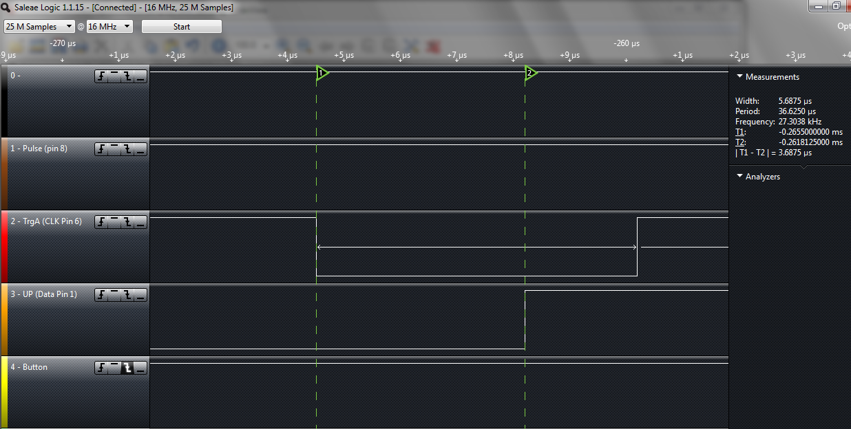
The latency was reduced down to 3.6us by:
- Pre-shifting the shiftRegister variable at the end of the interrupt
- Changing the pins by writing to registers DDR/PORT instead of use digitalWrite()
- Triggering the interrupt at the FALL of the clock signal.
// External Interrupt driven by Clock pin (6)
ISR(INT1_vect) {

   if (shiftRegister & (1<<15) ){
      OUT_DDR  &= ~(1<<0); // data on bit 0
      OUT_PORT |= (1<<0);
    } else {
      OUT_PORT  &= ~(1<<0);
      OUT_DDR |= (1<<0);
      }
    // shift regiter was pre-shifted
   digitalWrite(debugPin,HIGH);
   digitalWrite(debugPin,LOW);

    // pre-shift next bit
    shiftRegister<<=1;
}
Now the next data is ready even before the Z80 rise back the clock signal!
![]()
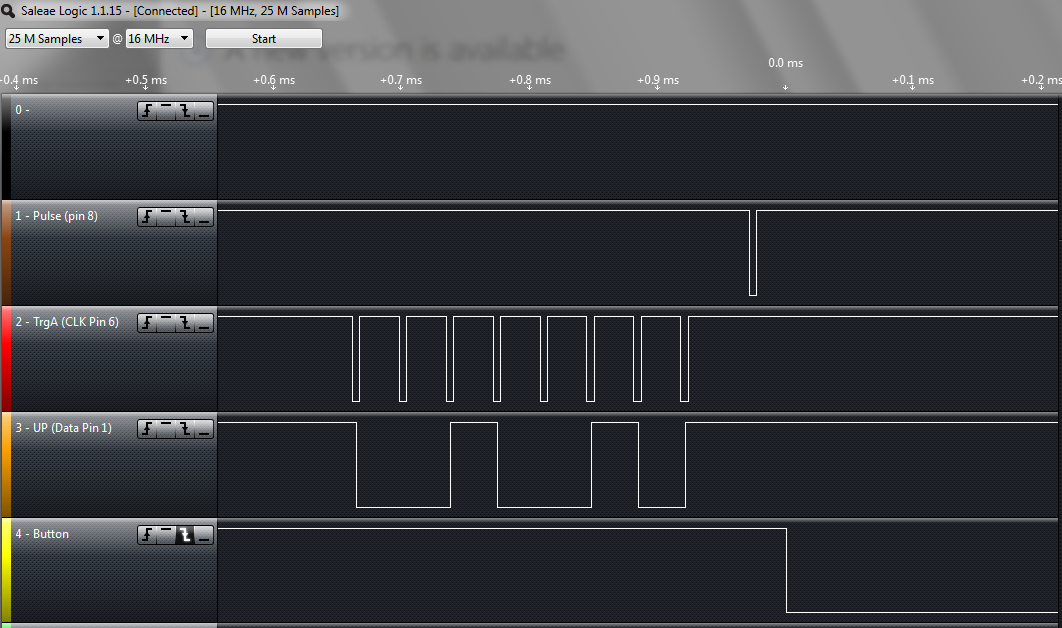
Last but not least, the capture below shows the moment that the button is sampled and the output (pin 2) is changed. The capure also shows the method of reading. As the ADC on the original Arkanoid controller takes too much time (3-10ms) to convert the potentiometer position, the shifts are shifted FIRST then a NEW SAMPLE is requested by a pulse on pin 8.
![]()