 Anton
Anton-
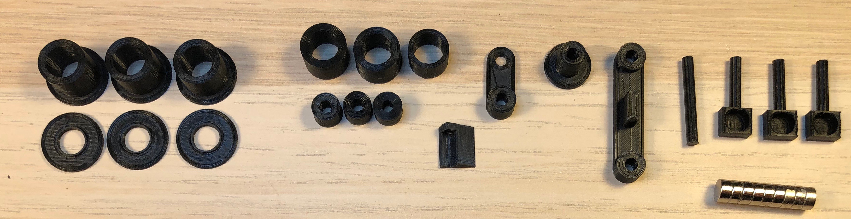
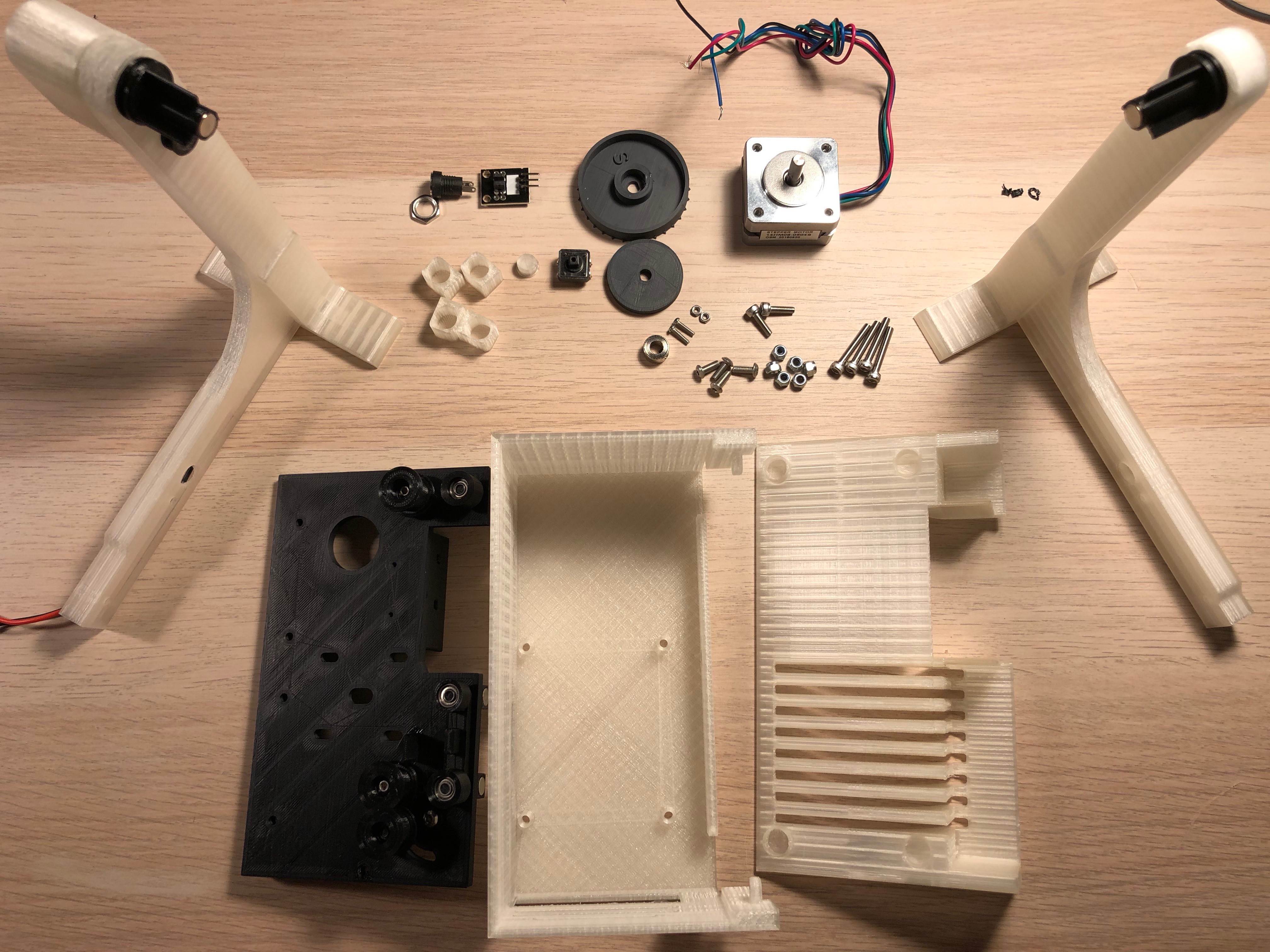
1Assembling the core
Beside the printed parts on the picture, you'll need:
Screws: 2pc M3x20mm, 1pc M3x12mm. 1pc M2x8mm
Nuts: 5pc M3 Self locking, 1pc M2
Magnets: 9pc 6x3mm
Bearings: 6pc 3x8x4mm
![]()
![]()
Glue the magnets into the holes of the mount plate as well as the 3 roll axles:
Important! - Check the polarity: the axle hast to stick to the magnets in the mount plate in the upper and lower position.

![]()
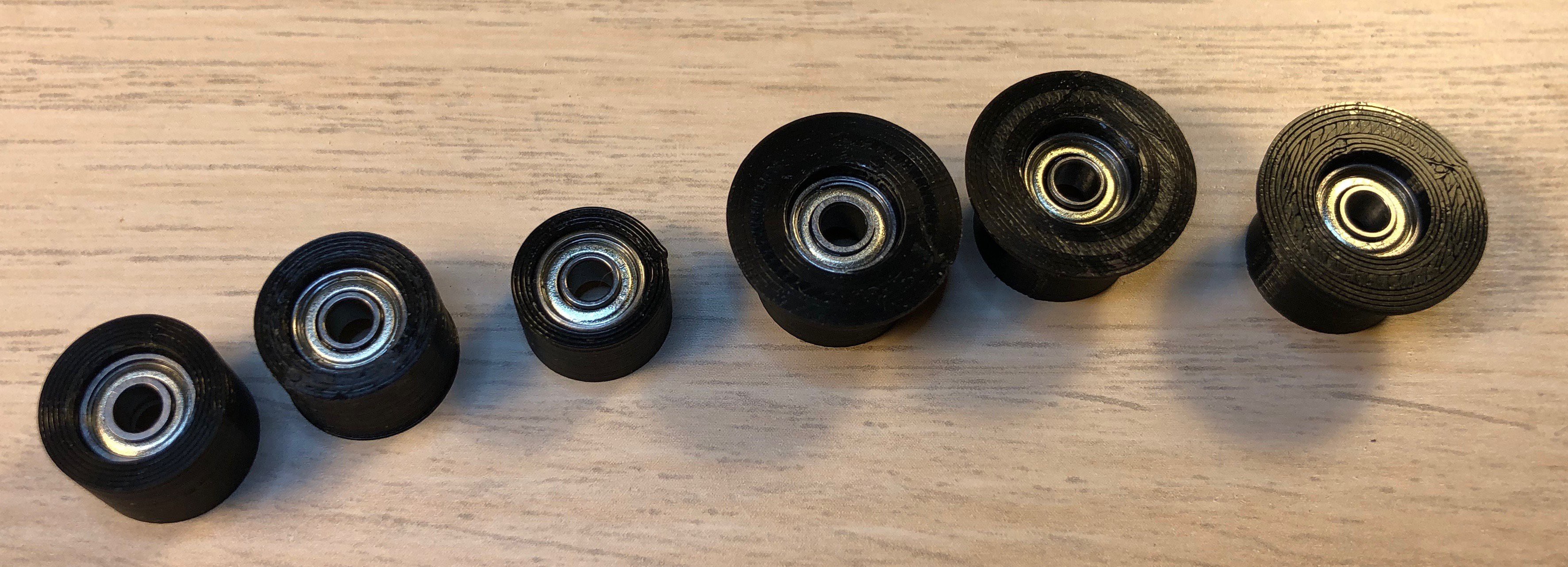
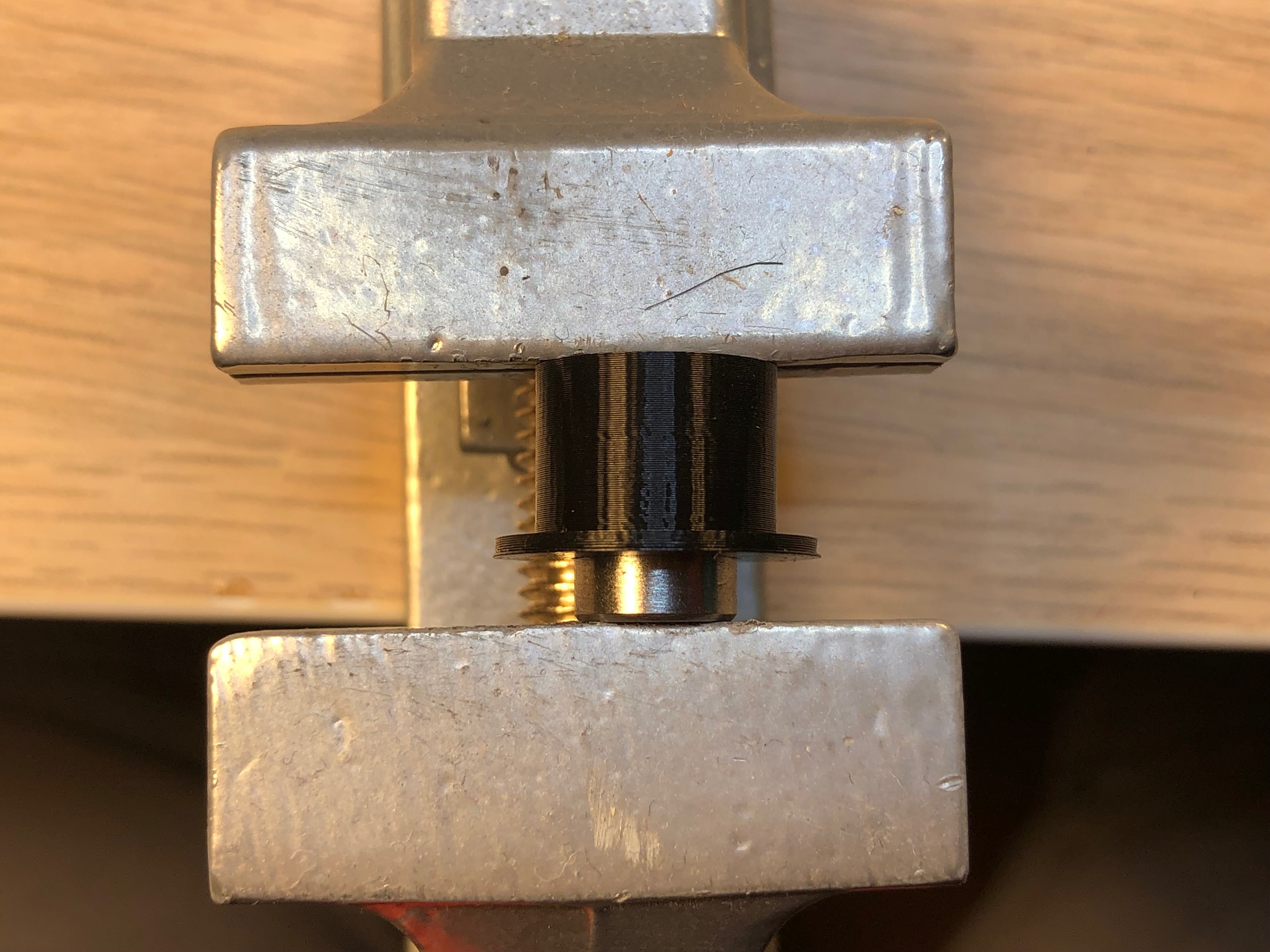
Push the bearings into the rolls: Don't worry to use some force - I use a vise for that.
Afterwards glue the sides on the 3 larger rolls.
![]()
all bearings in place ![]()
assembled rolls ![]()
using the vise Now put the axles through the mount plate and the roll mover (or roll spacer) and push the rolls on it. No need to adjust them yet.
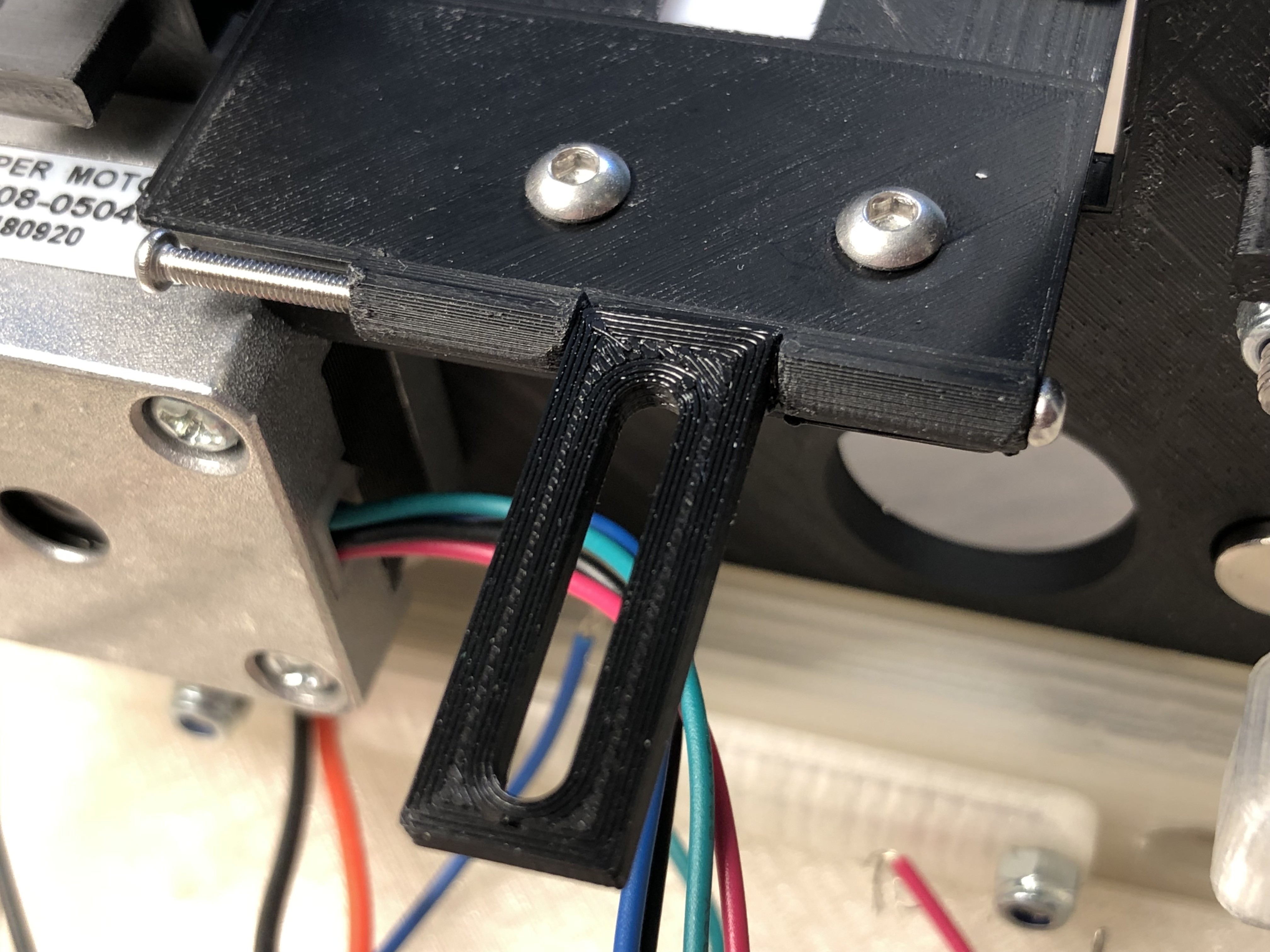
Mount the 2 lower rolls with M3x20 screws and the interrupter lever with an M3x12mm screw. The film clearer is mounted with the M2 screw. Add 2 M3 nuts at the bottom of the latch (see picture of the back view)
Ensure all rolls are running smooth and the upper rolls are locking in the upper and lower positions.
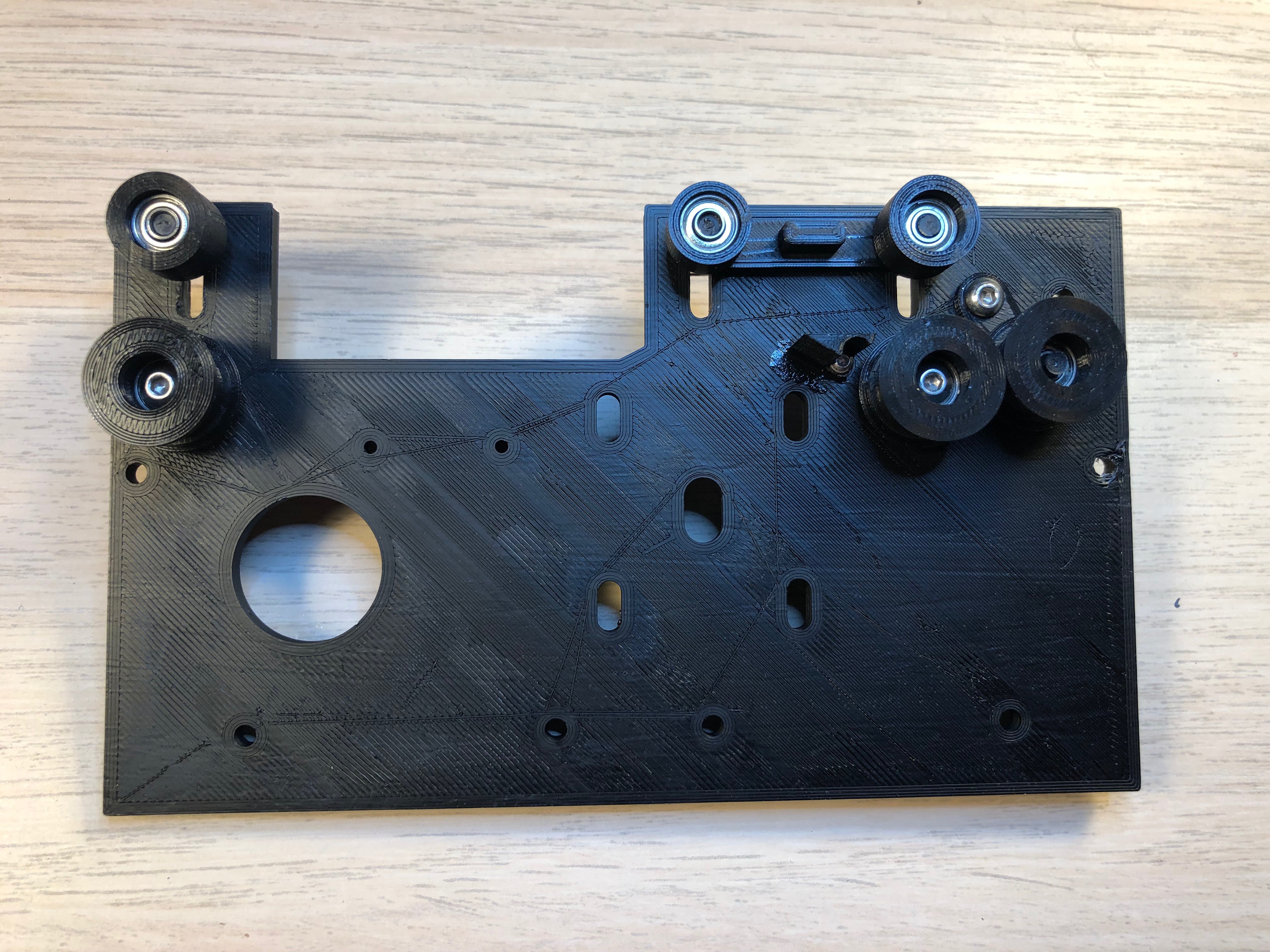
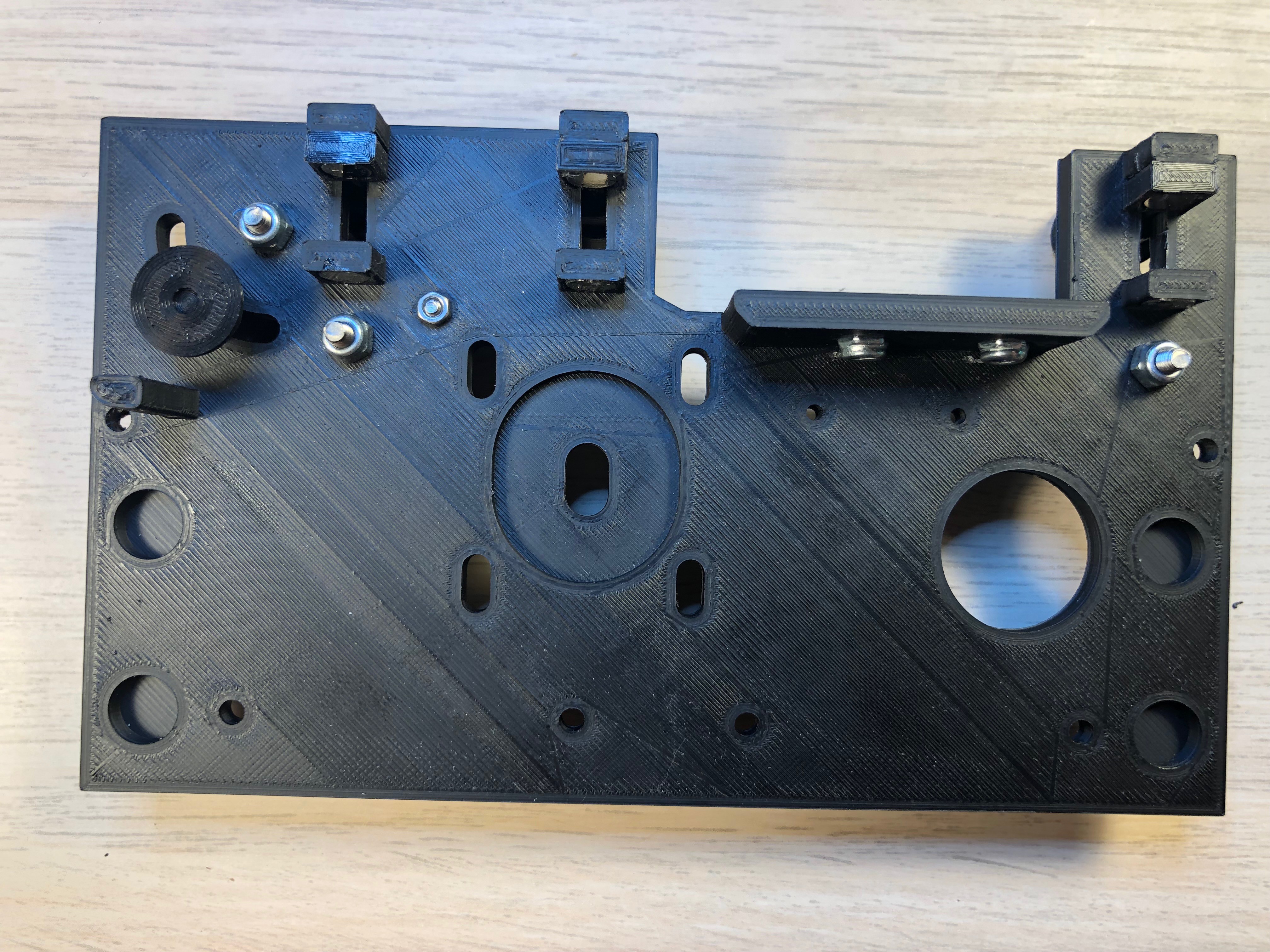
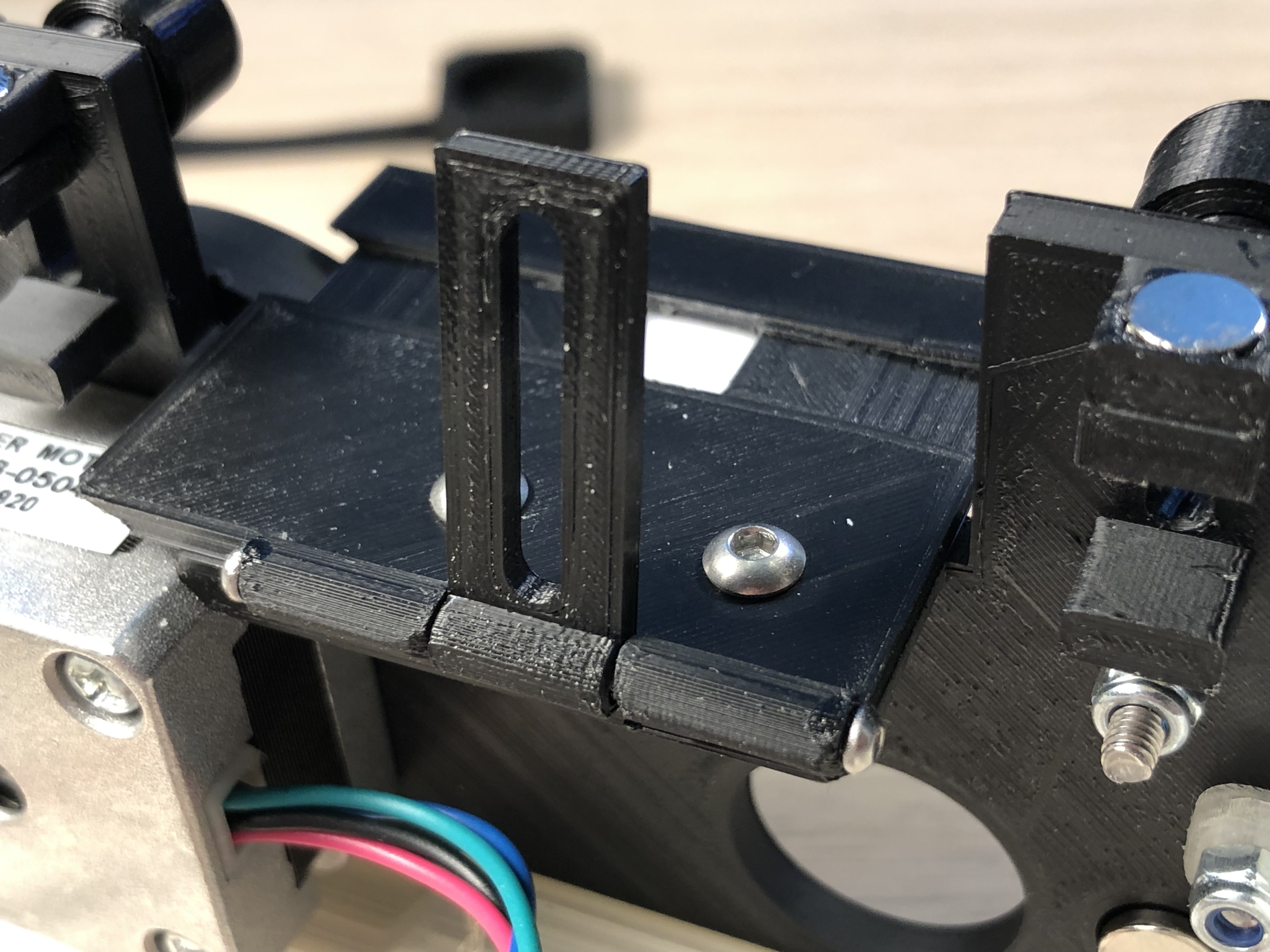
The result should look something like this:
![]()
Front ![]()
Back move on the step 2
-
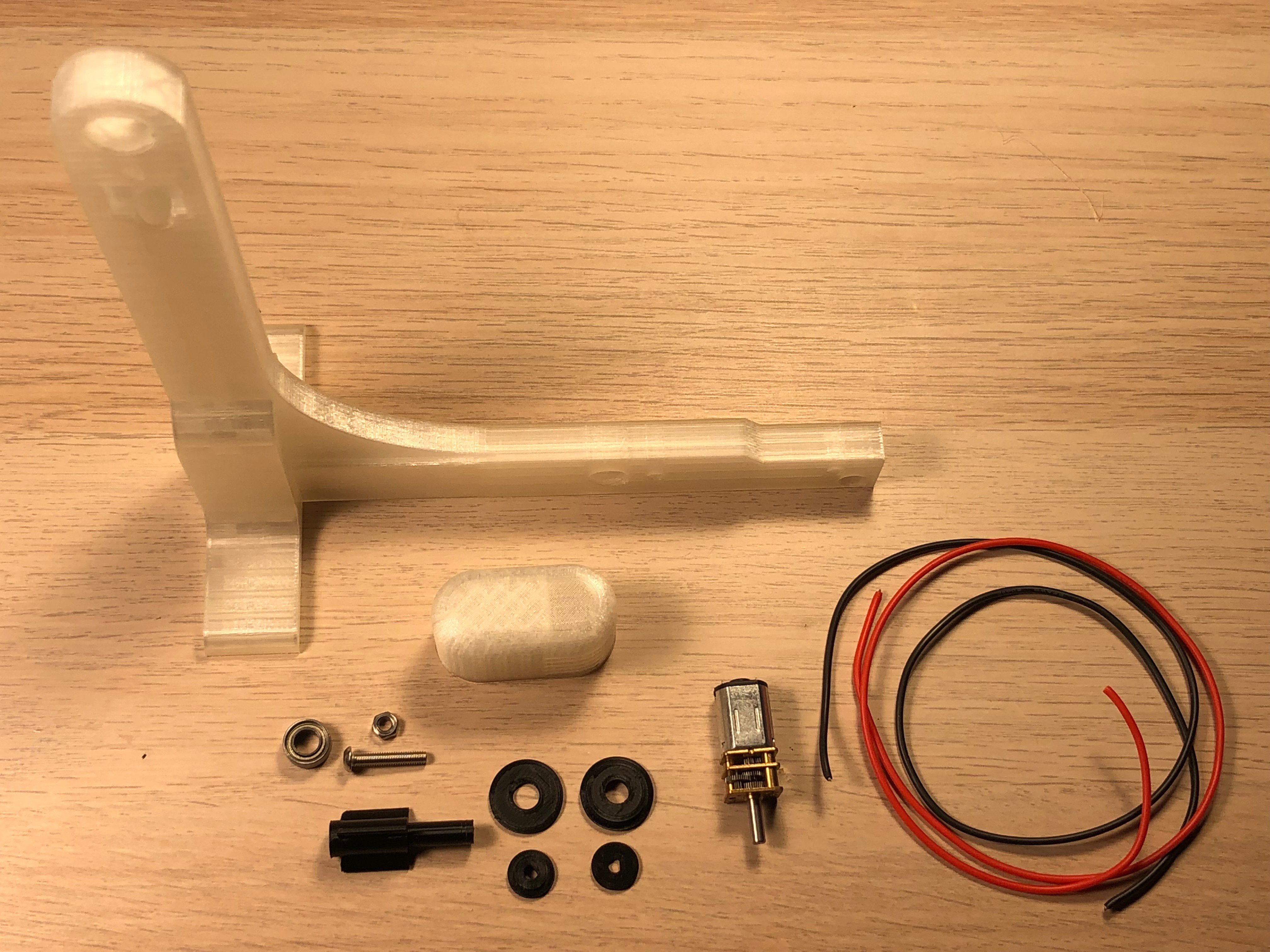
2Assemble the motorized spool holder
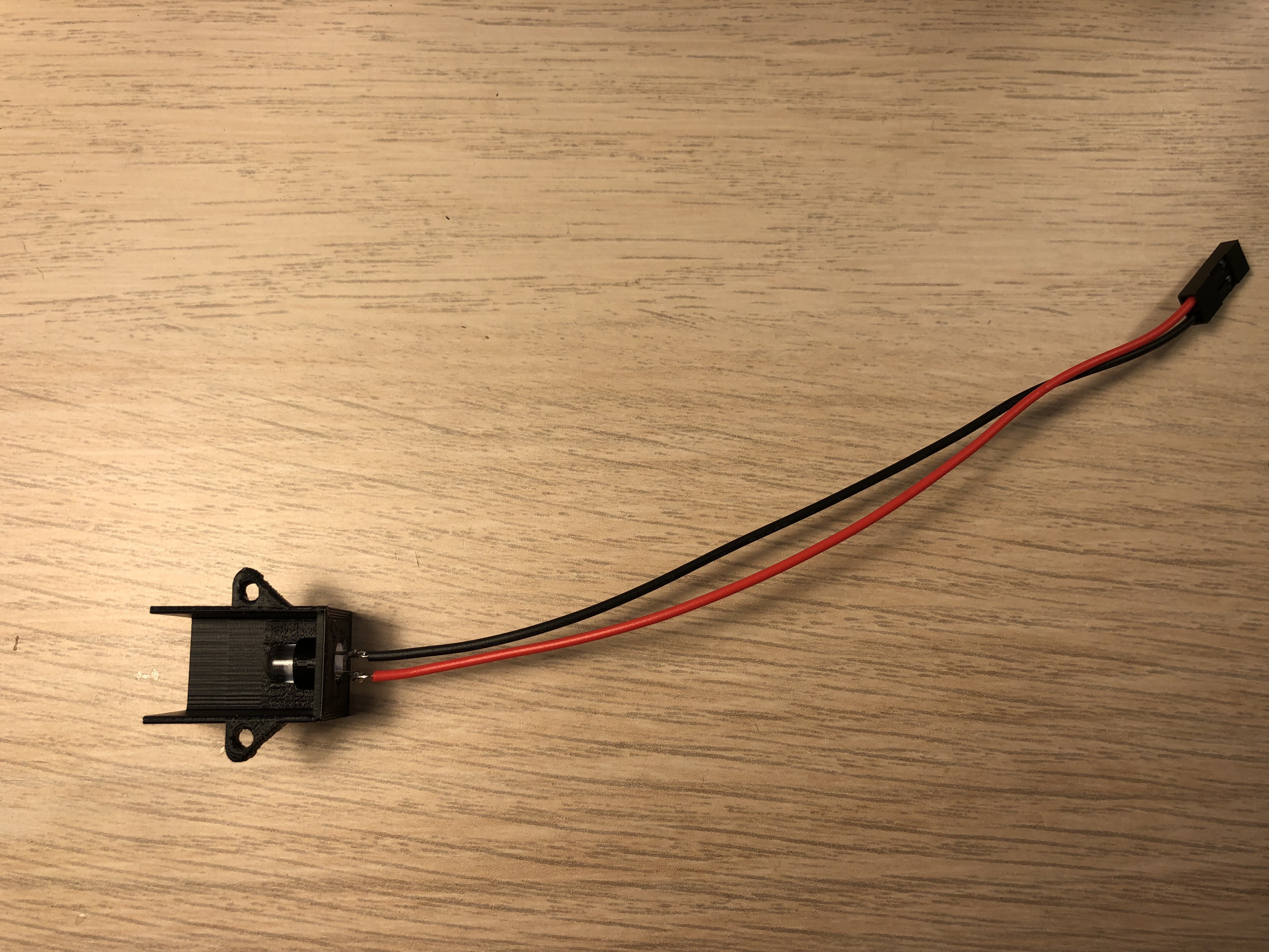
Beside the printed parts as shown, you'll need the geared motor (6V 60U/min) a ball bearing 5x10x4mm a M3x16 screw + nut a magnet 6x3 (not on the photo) and some cable.
![]()
Pull through the cables:
![]()
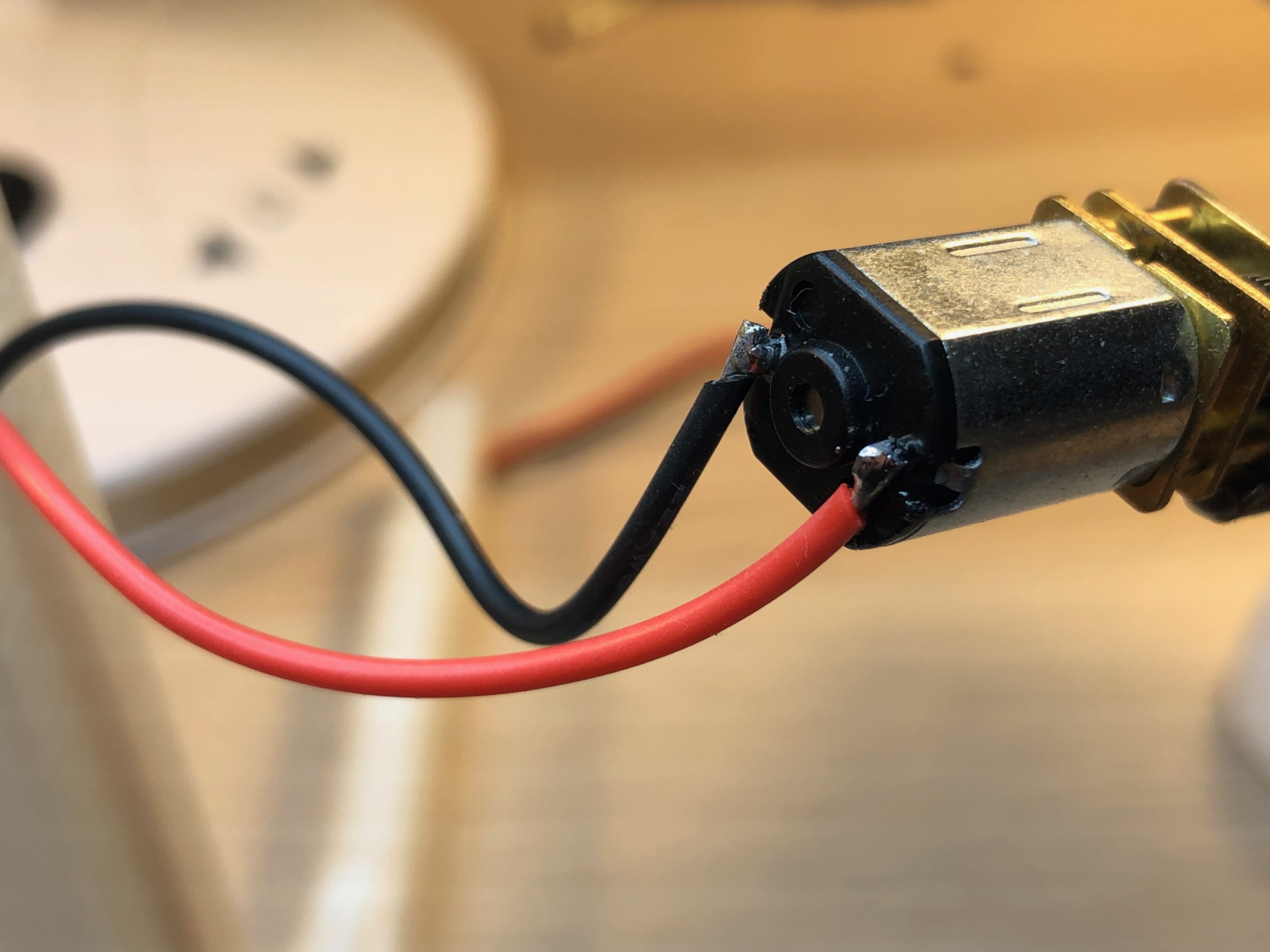
Solder the geared motor:
![]()
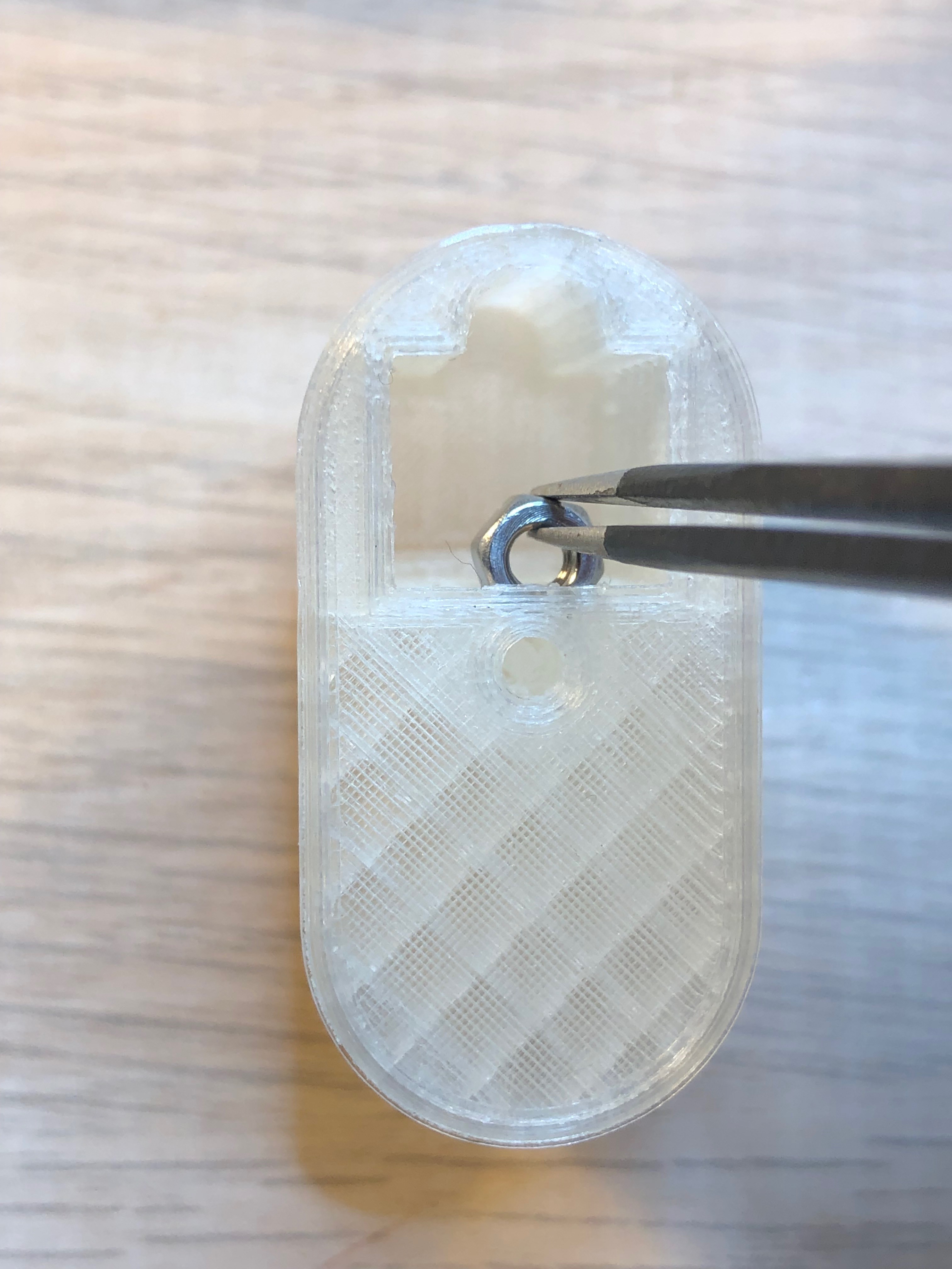
Put the nut in the motor cover:
![]()
Put in the motor:
![]()
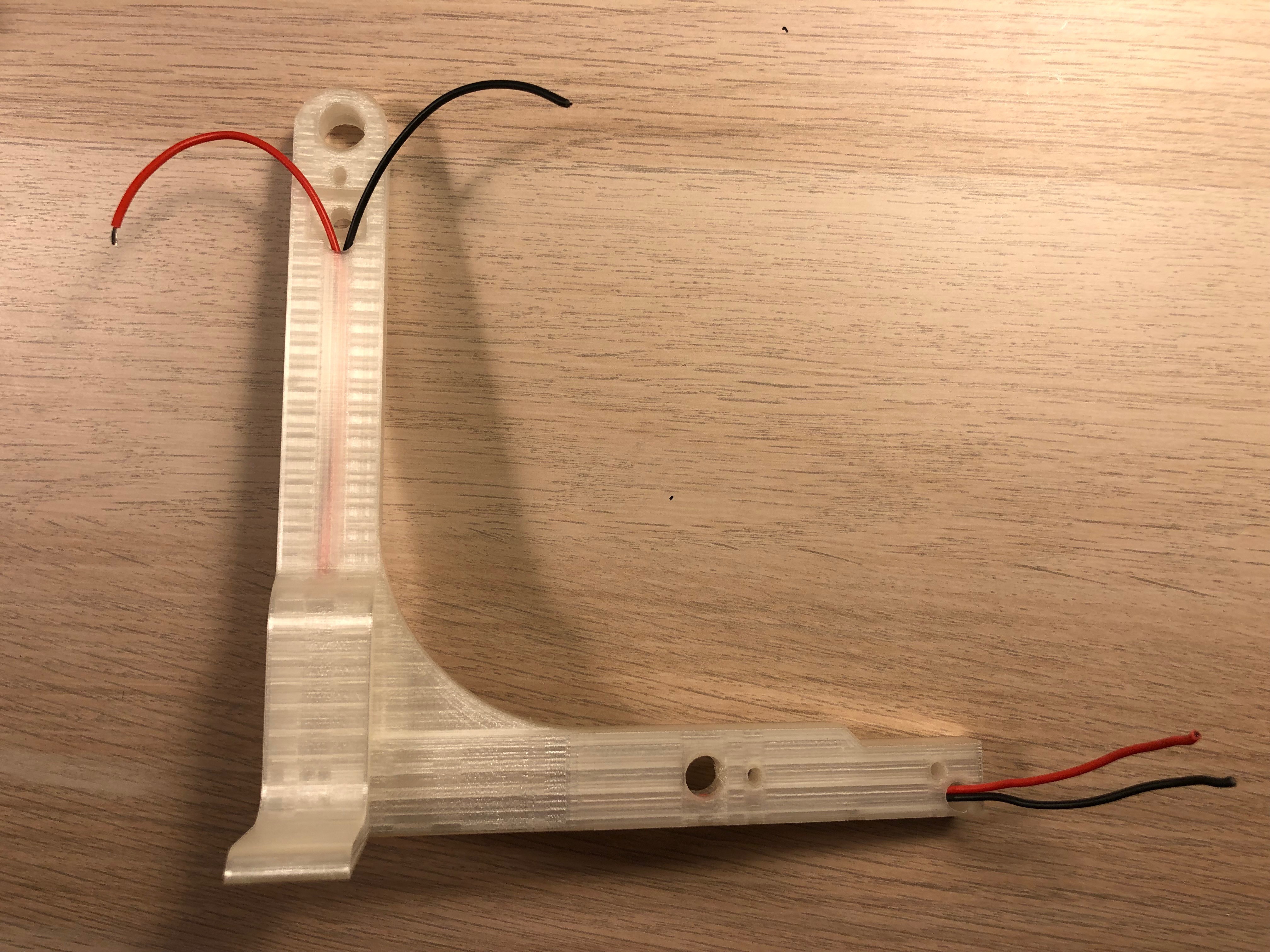
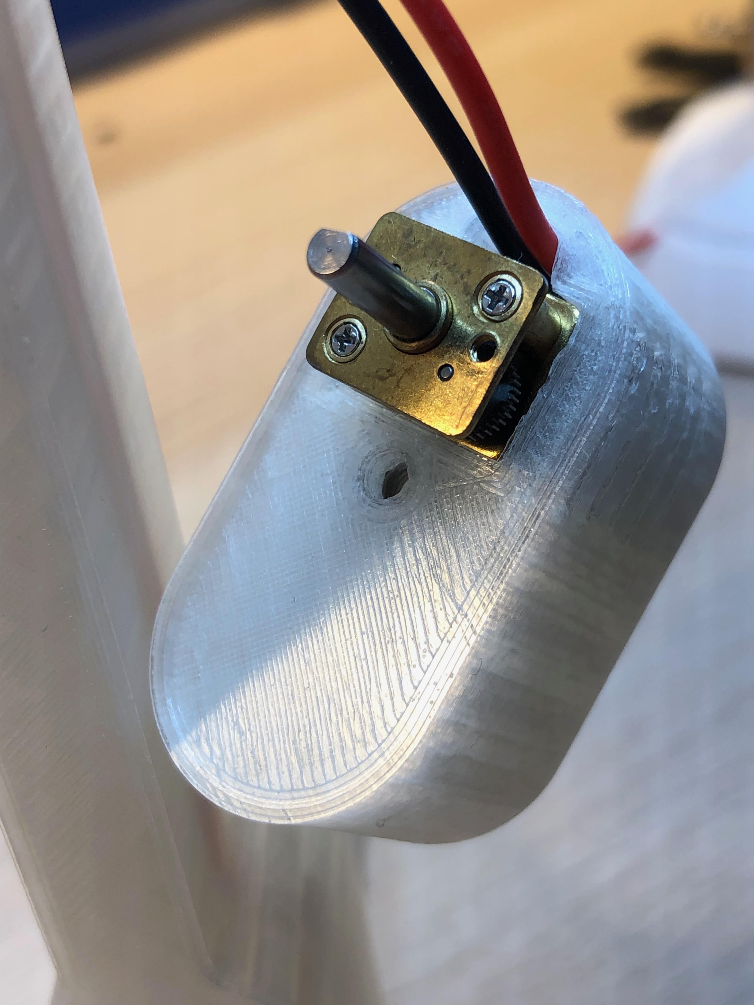
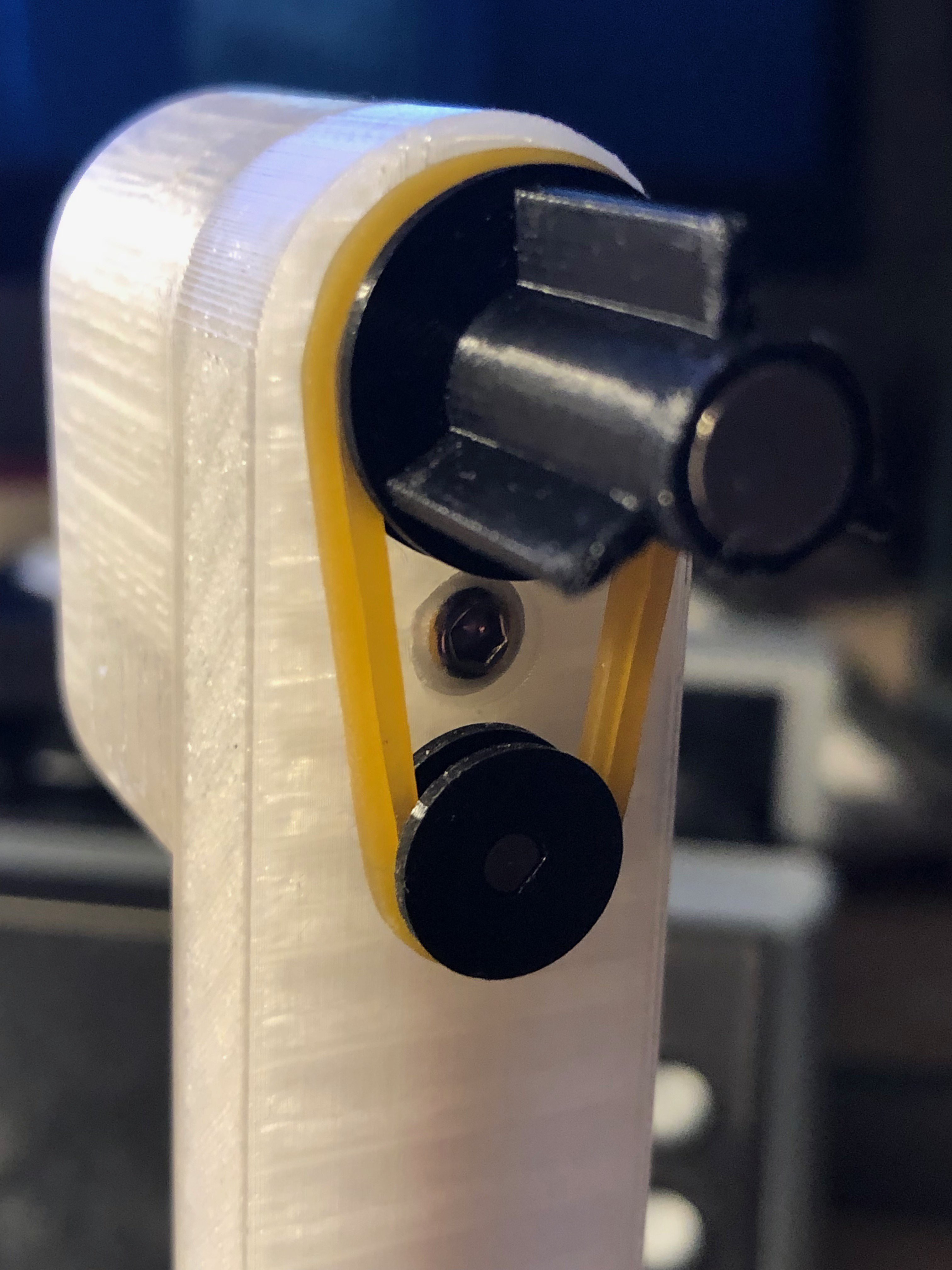
Use the M3 screw to mount it to the arm:
![]()
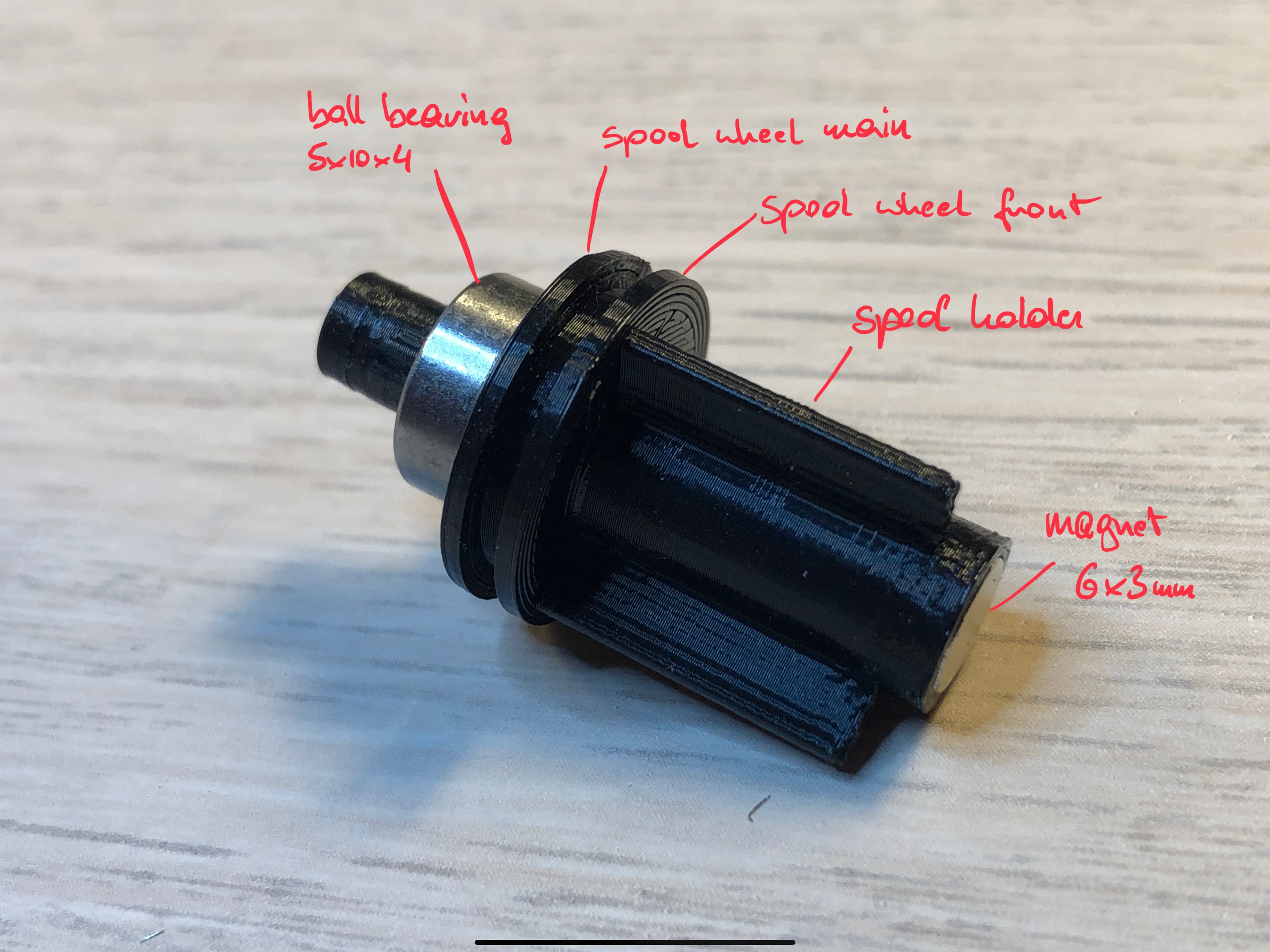
Assemble the spool holder by gluing the printed parts together and push the bearing on - it should sit very tight! Glue in the magnet. Important: You will find 2 very similar parts in your prints for the spool holder, one for each side. Here you use the slightly longer one.
![]()
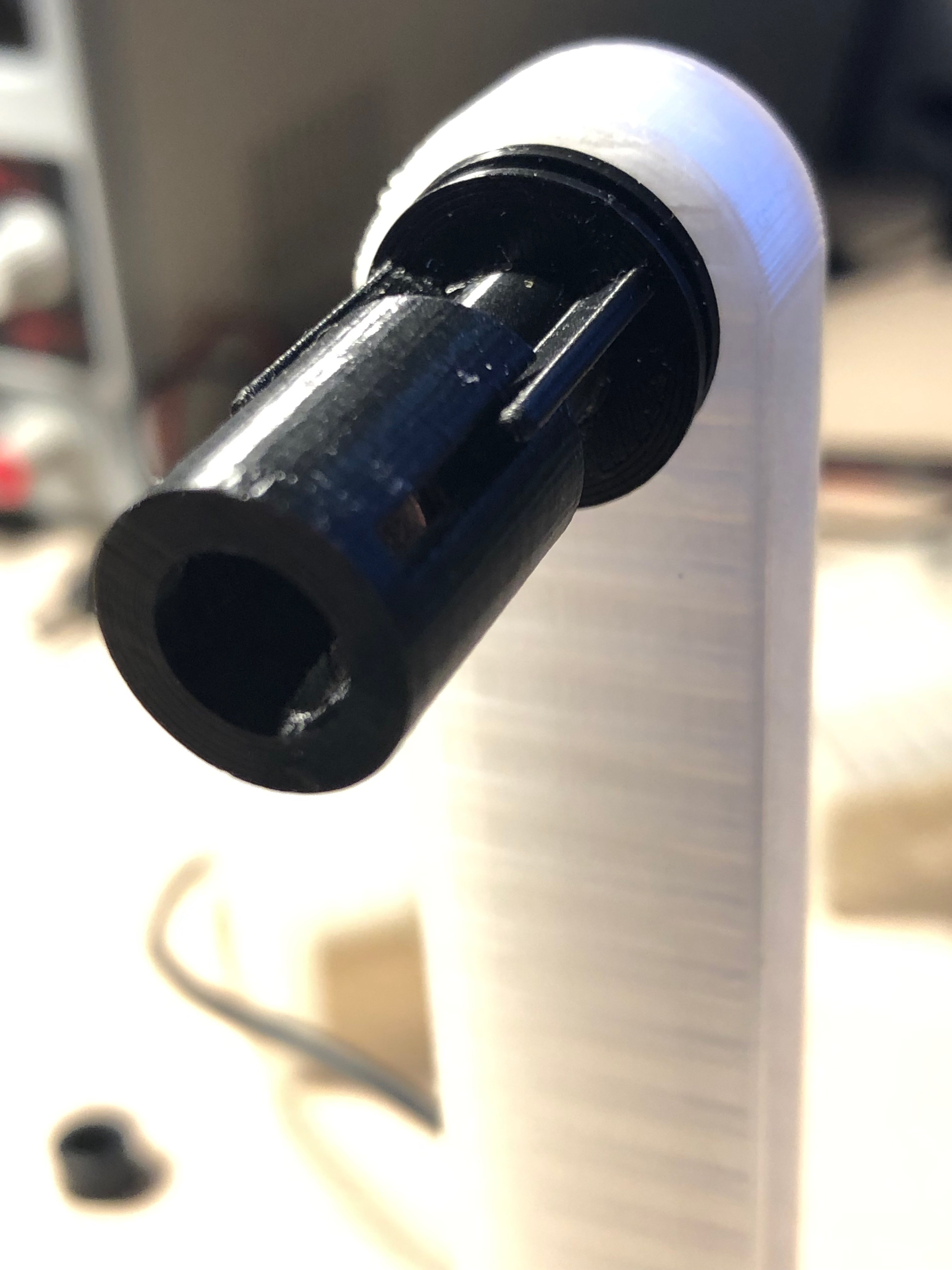
Push the holder into the arm - also here the bearing should fit very tight.
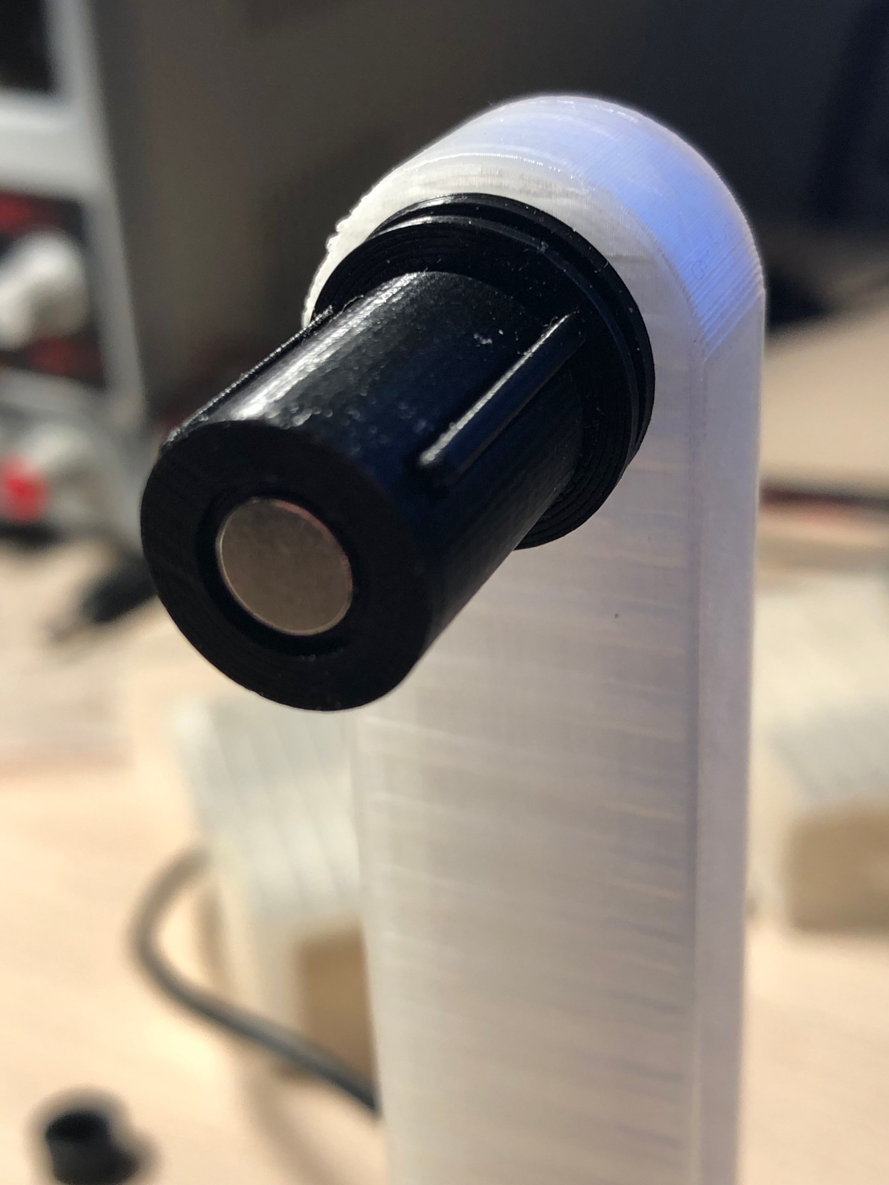
Put the spool motor wheel main part onto the motor axle and glue the motor wheel front to the main. (not the axle)
![]()
Assemble the 2nd spool holder and put it into the other spool arm.
-
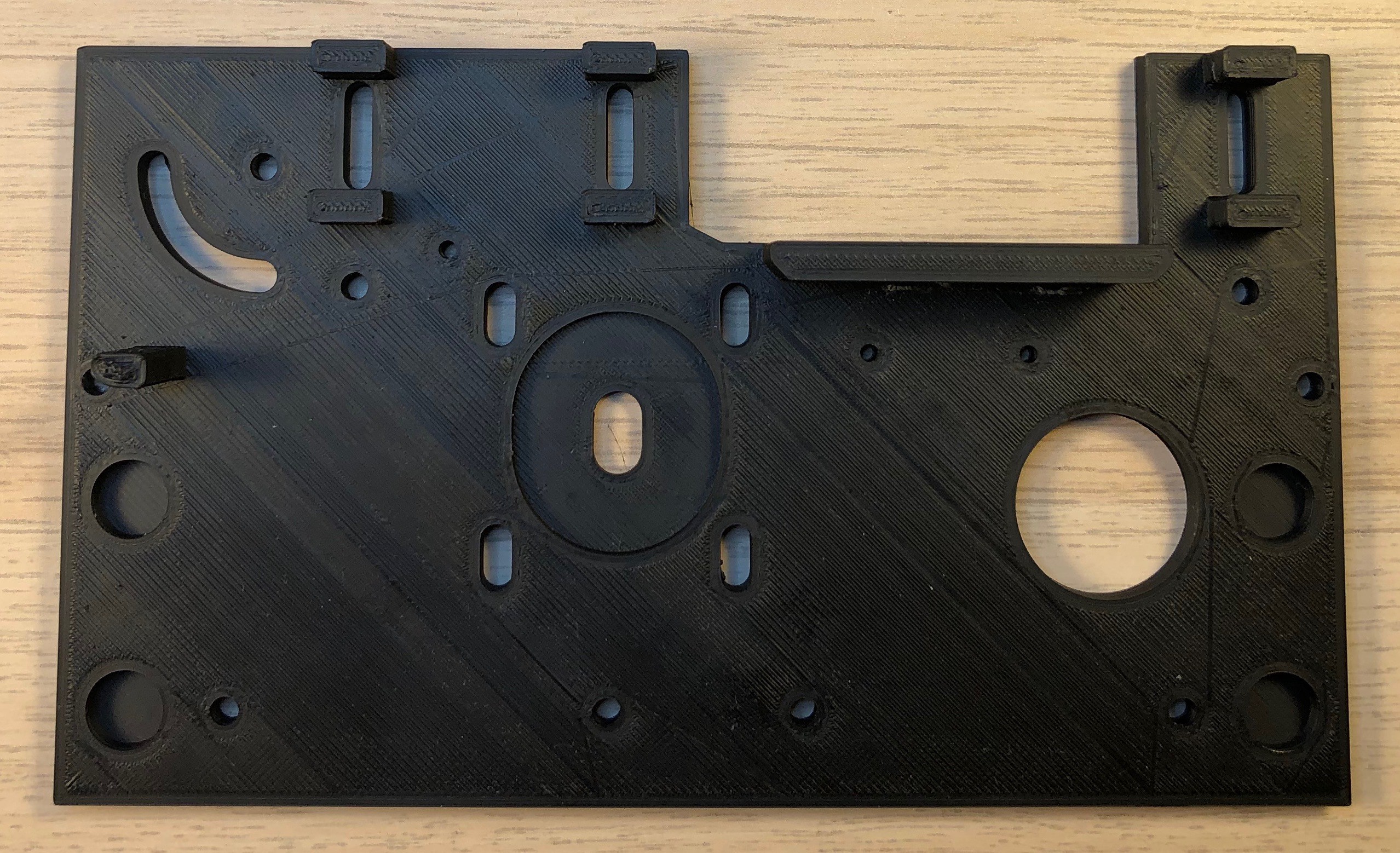
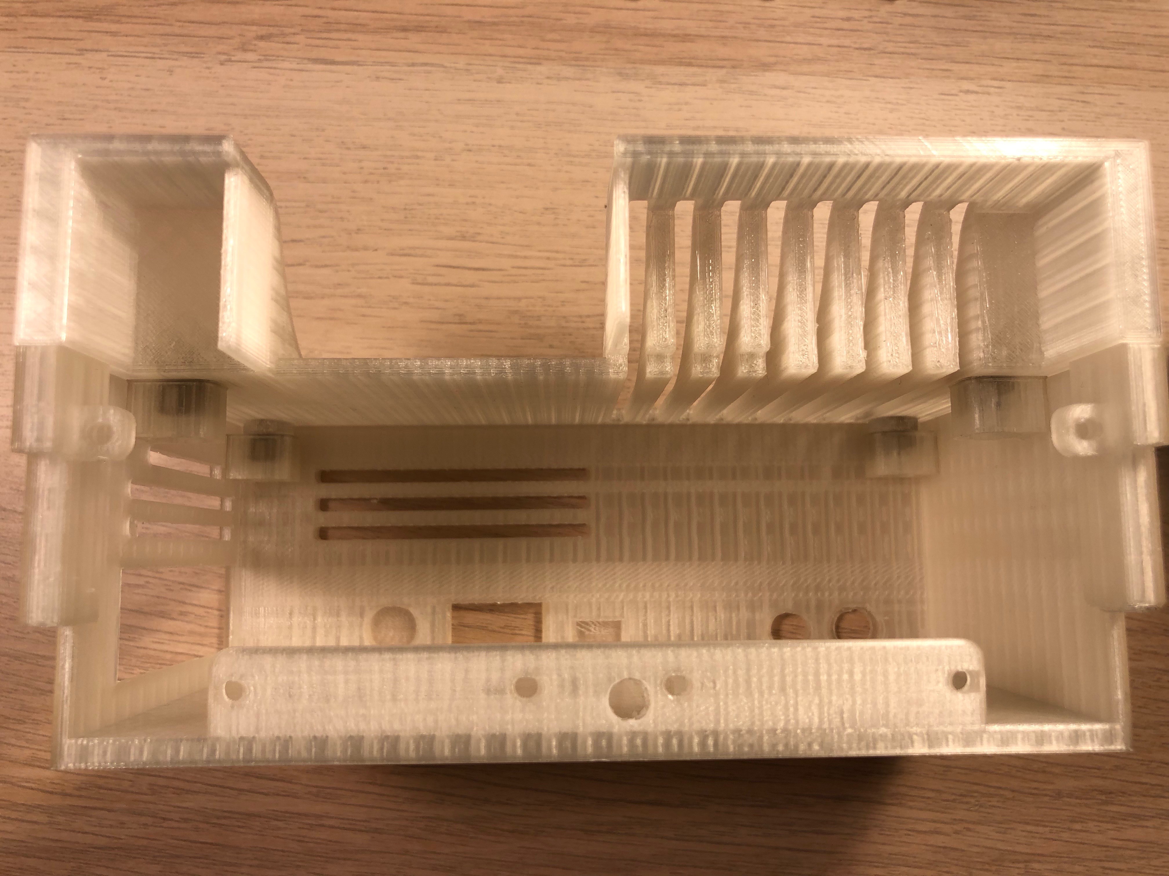
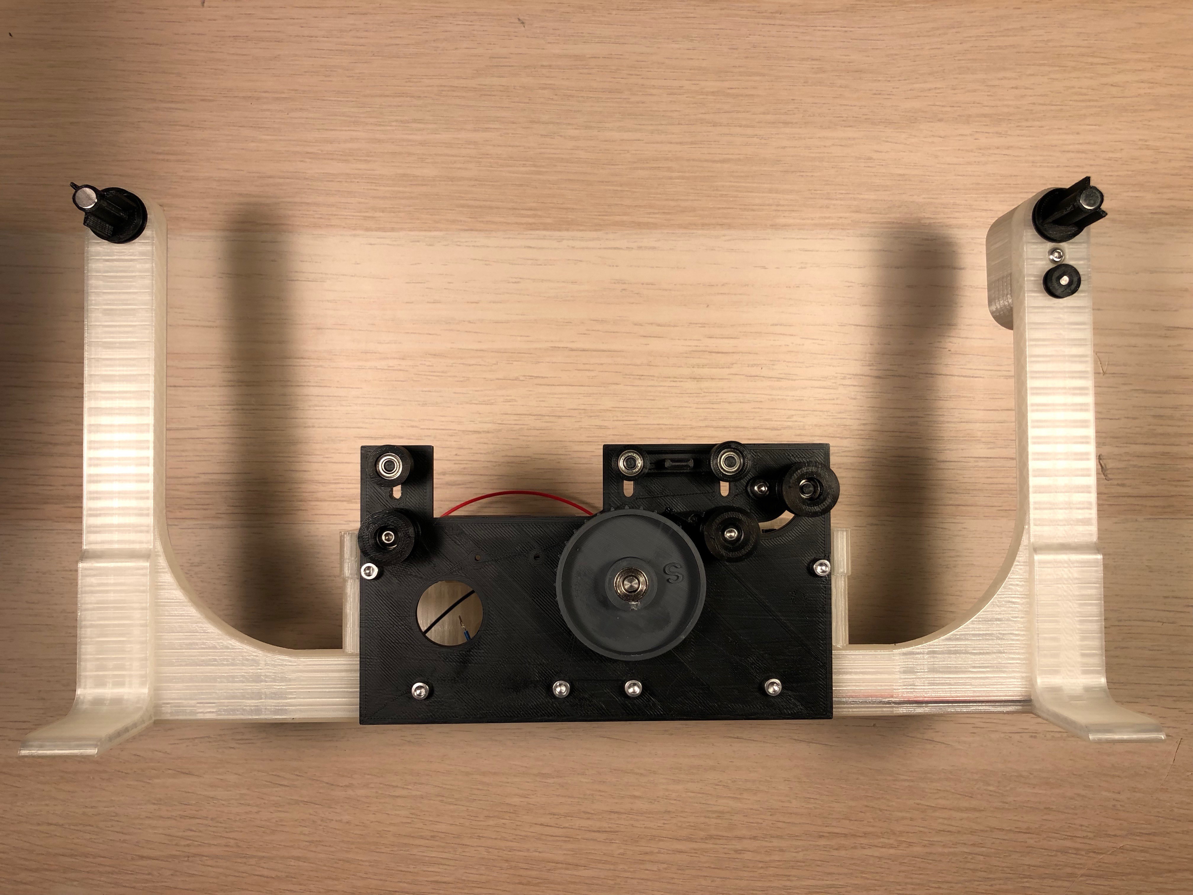
3Putting together what we've built so far
You'll need screws: 4 M3x20, 2 M3x10, 4 M3x6mm, 6 self locking nuts M3, 2 M2x6 + nuts, 12 magnets 8x5mm, Photo Interrupter Sensor Module, the stepper motor, 1 Steel Shaft Sleeve 5.05mm, 1 DC Power Jack 5.5 x 2.1mm, 1 Button 12x12mm
![]()
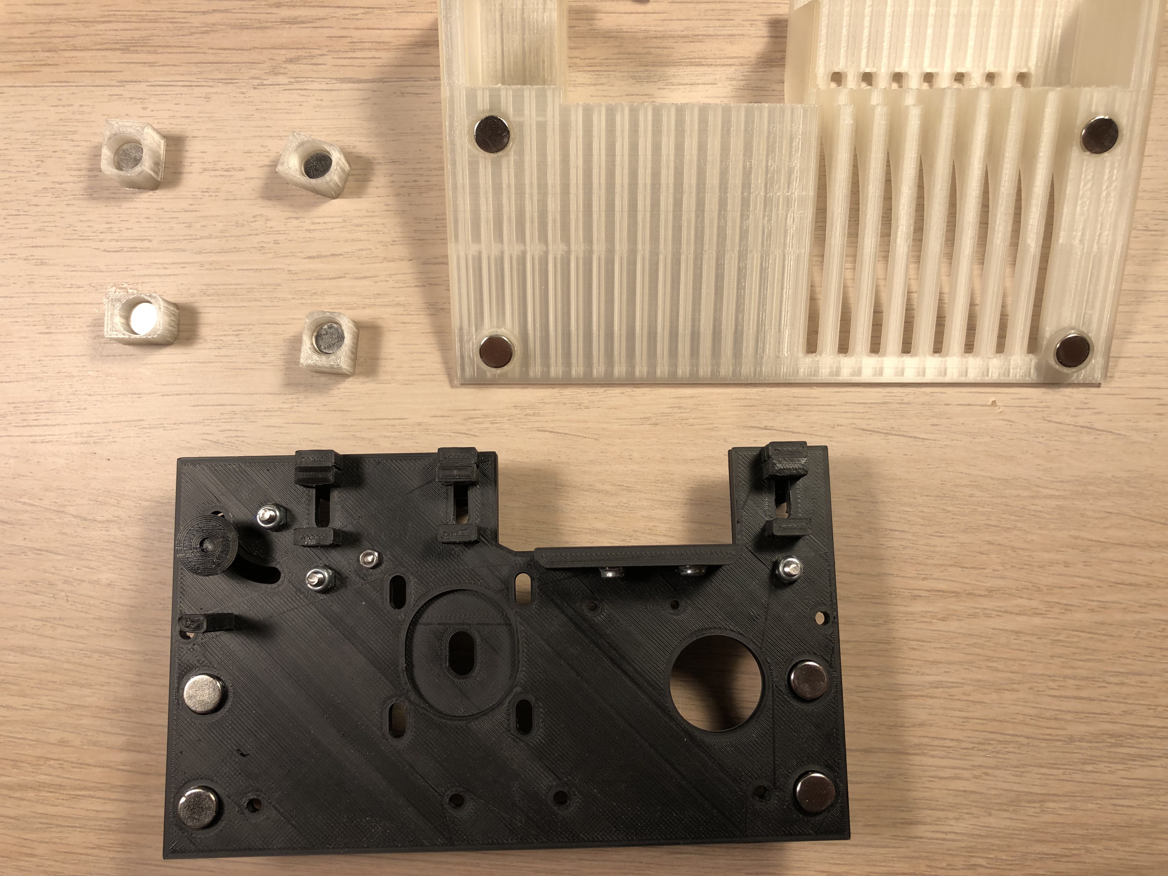
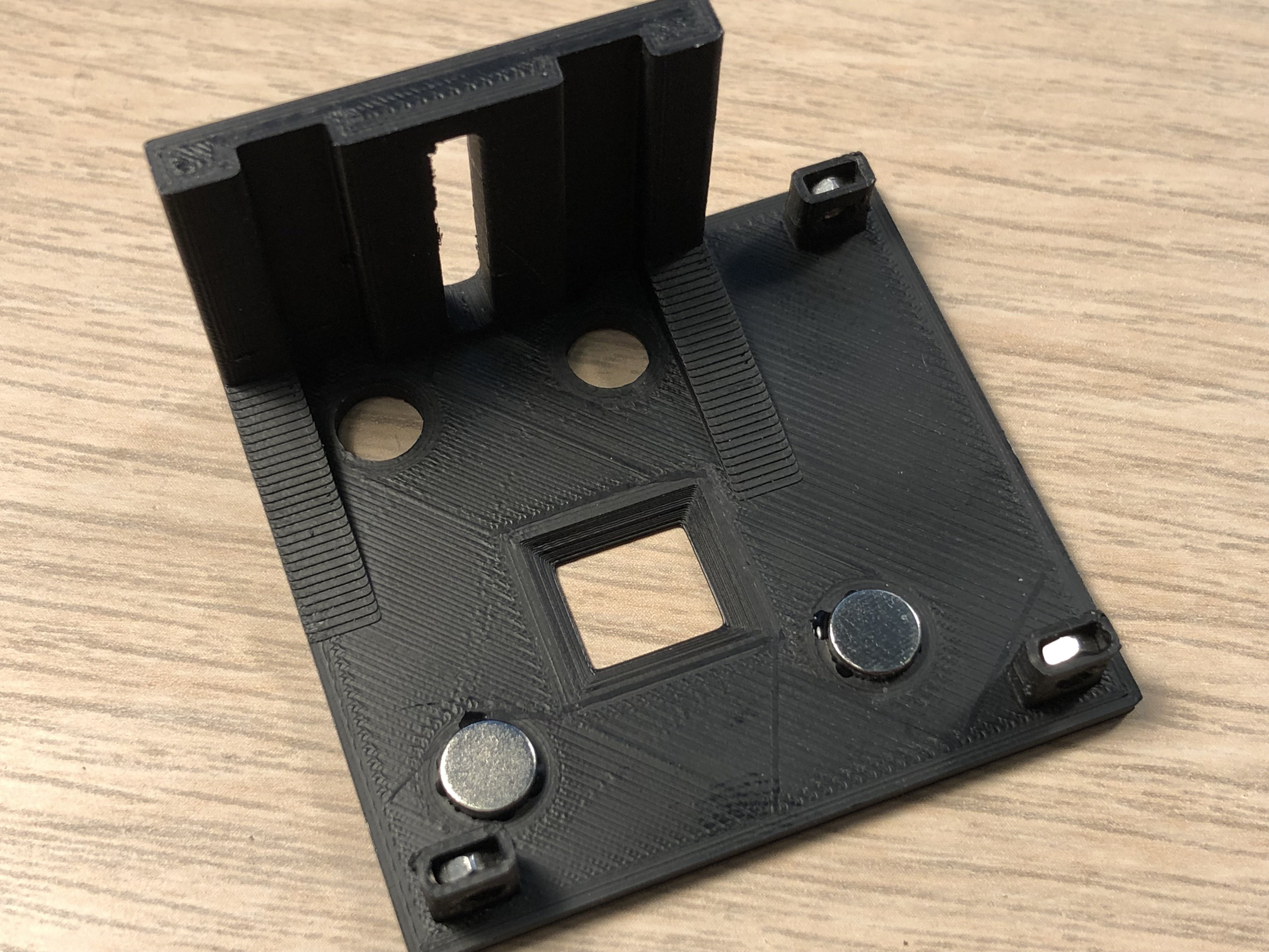
Glue the magnets into the holes:
![]()
Polarity: the Magnets in the 4 magnet holder should stick to the magnets in the cover like that:
![]()
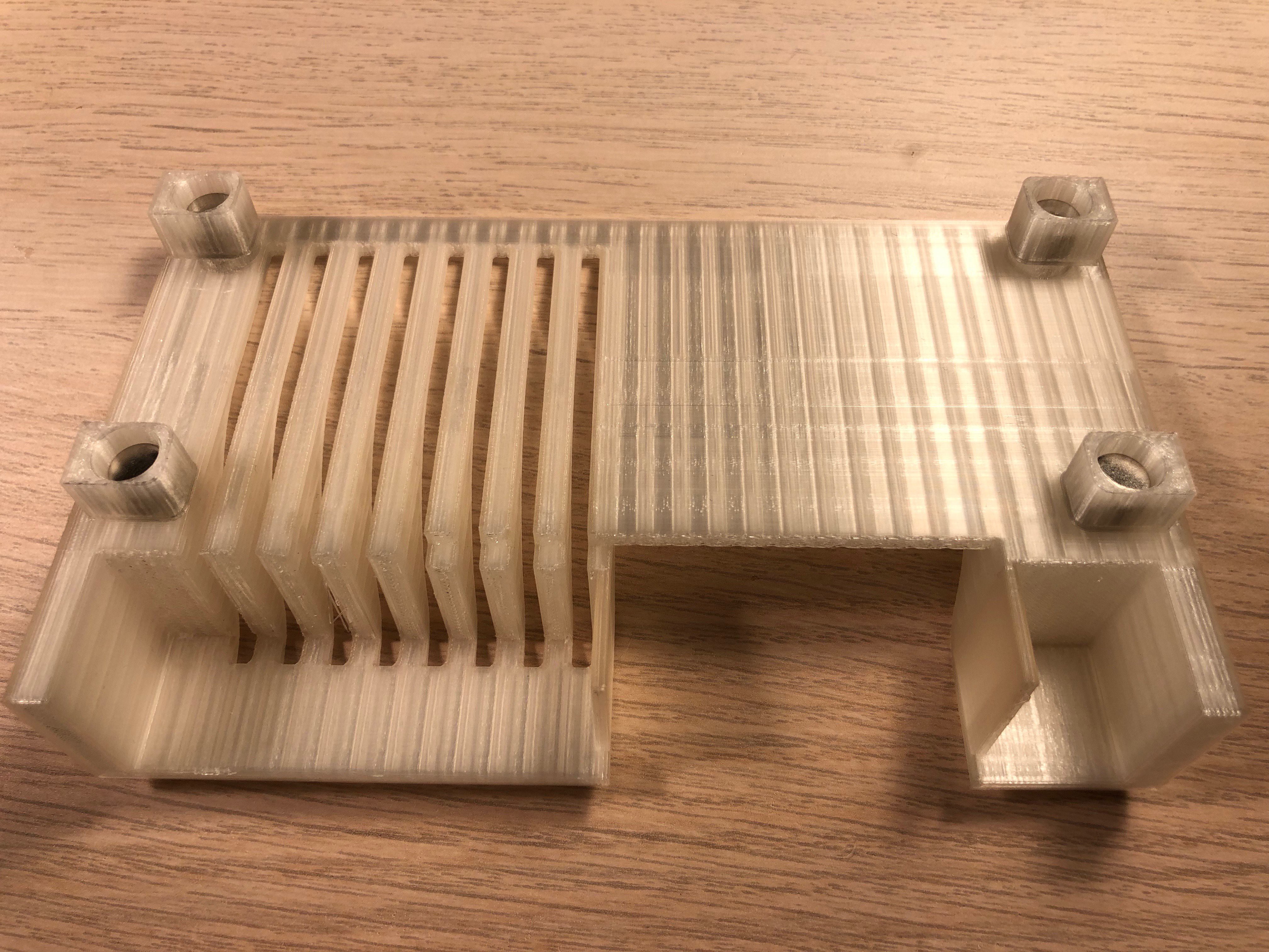
Add a bit of super glue on the outer ends of the holders and put the cover on the back cover box, that way the cover will fit exactly on the box.
![]()
Mount the power jack and the button. I use hot glue for the button.
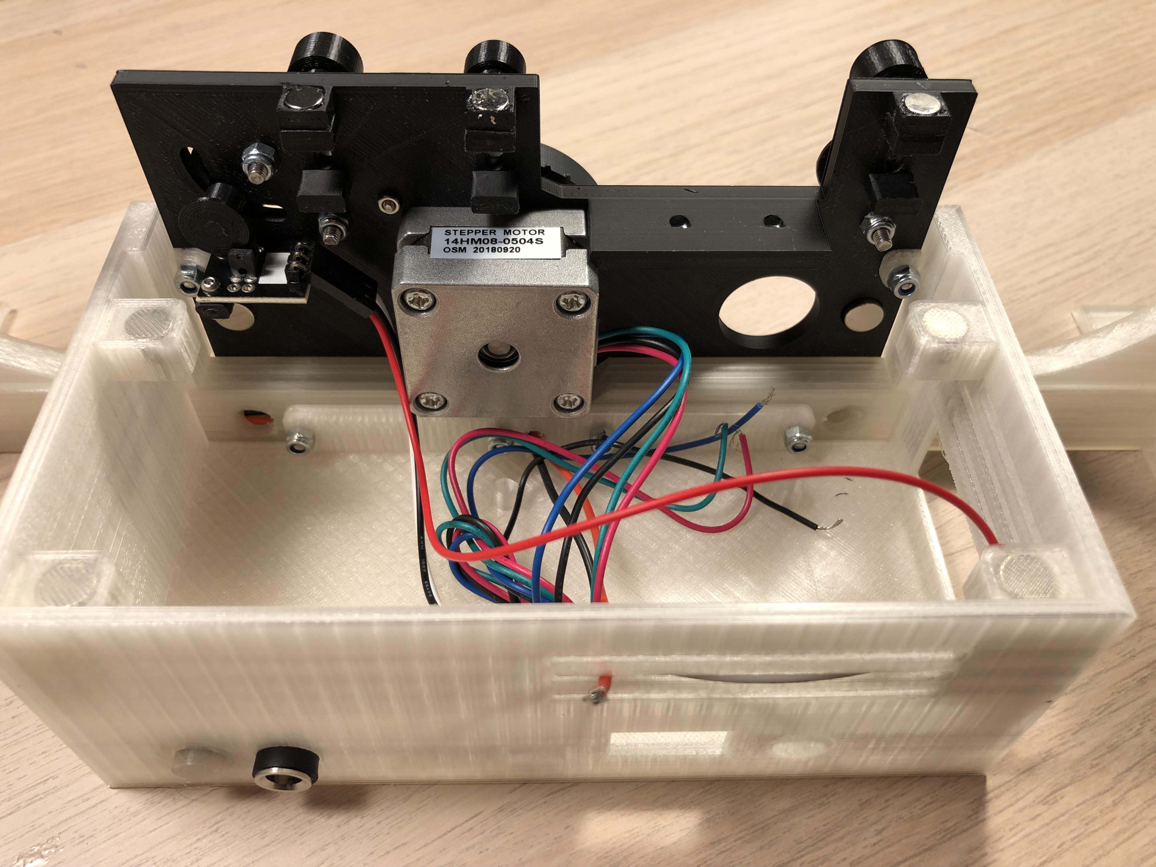
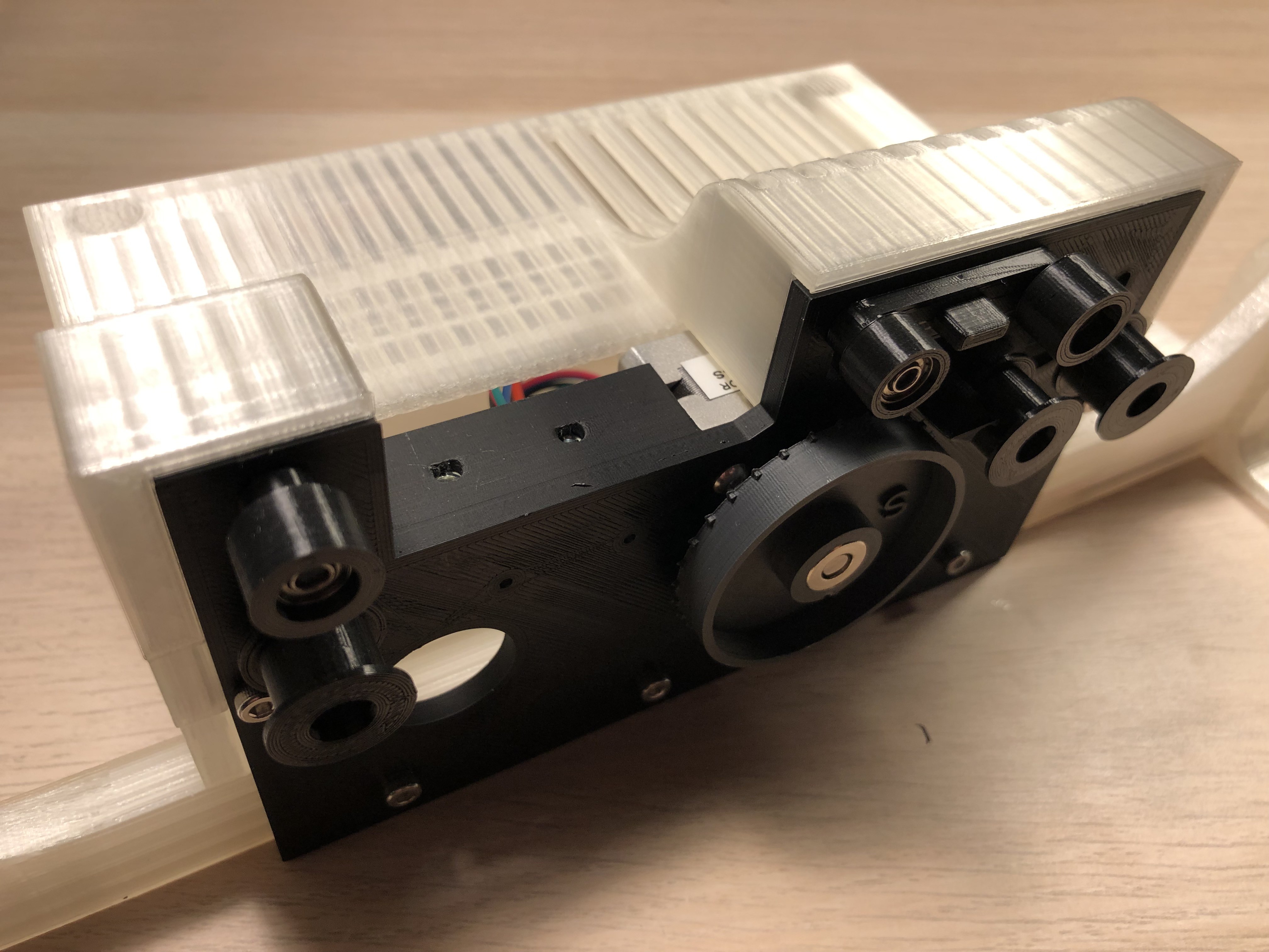
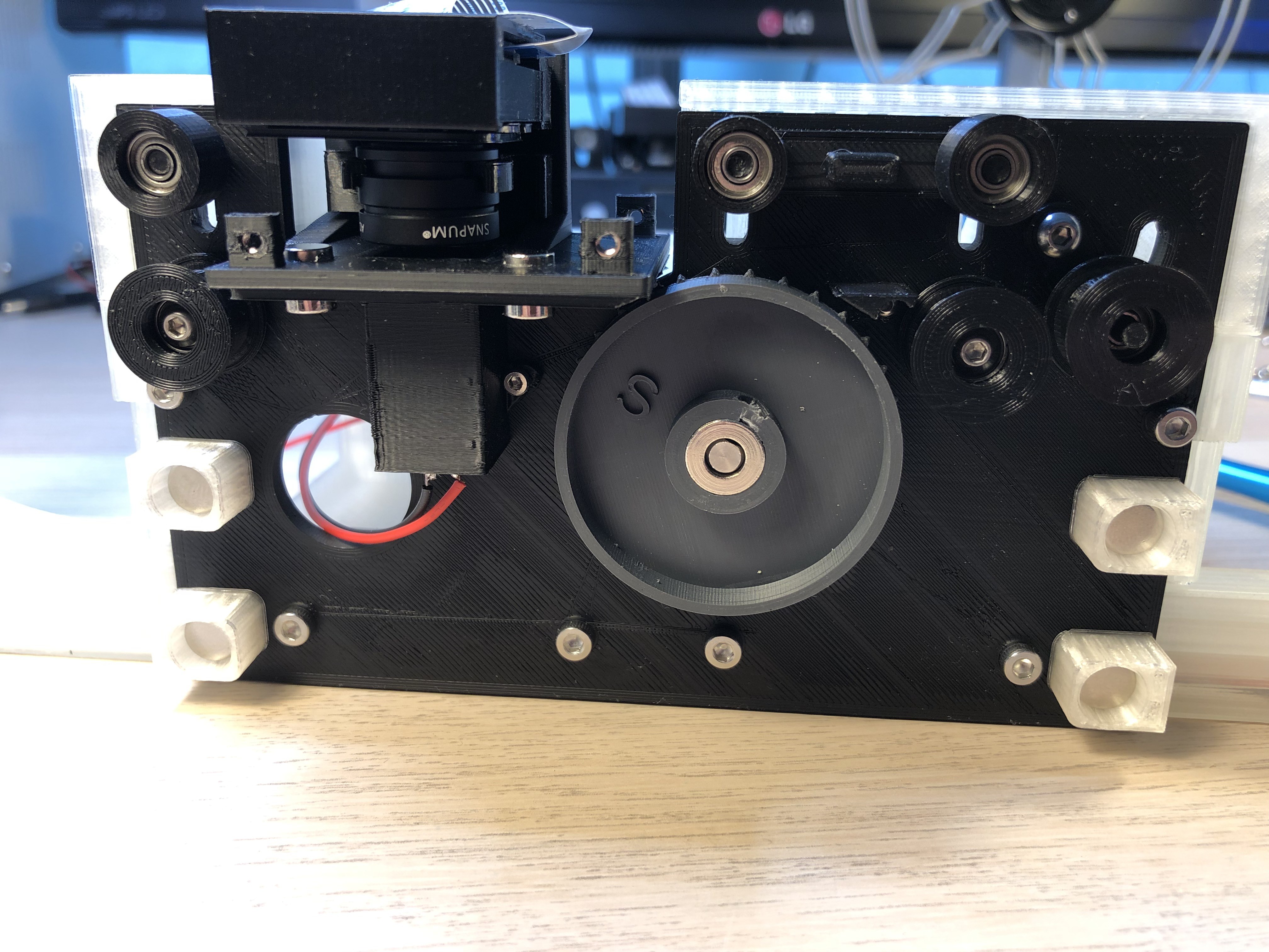
Add the photo interruptor with the 2 M2 screws, the stepper with the 4 M3x6mm screws and mount the plate to the box. The M3x20 screws have to go through the mount plate, the spool arms and the box.
![]()
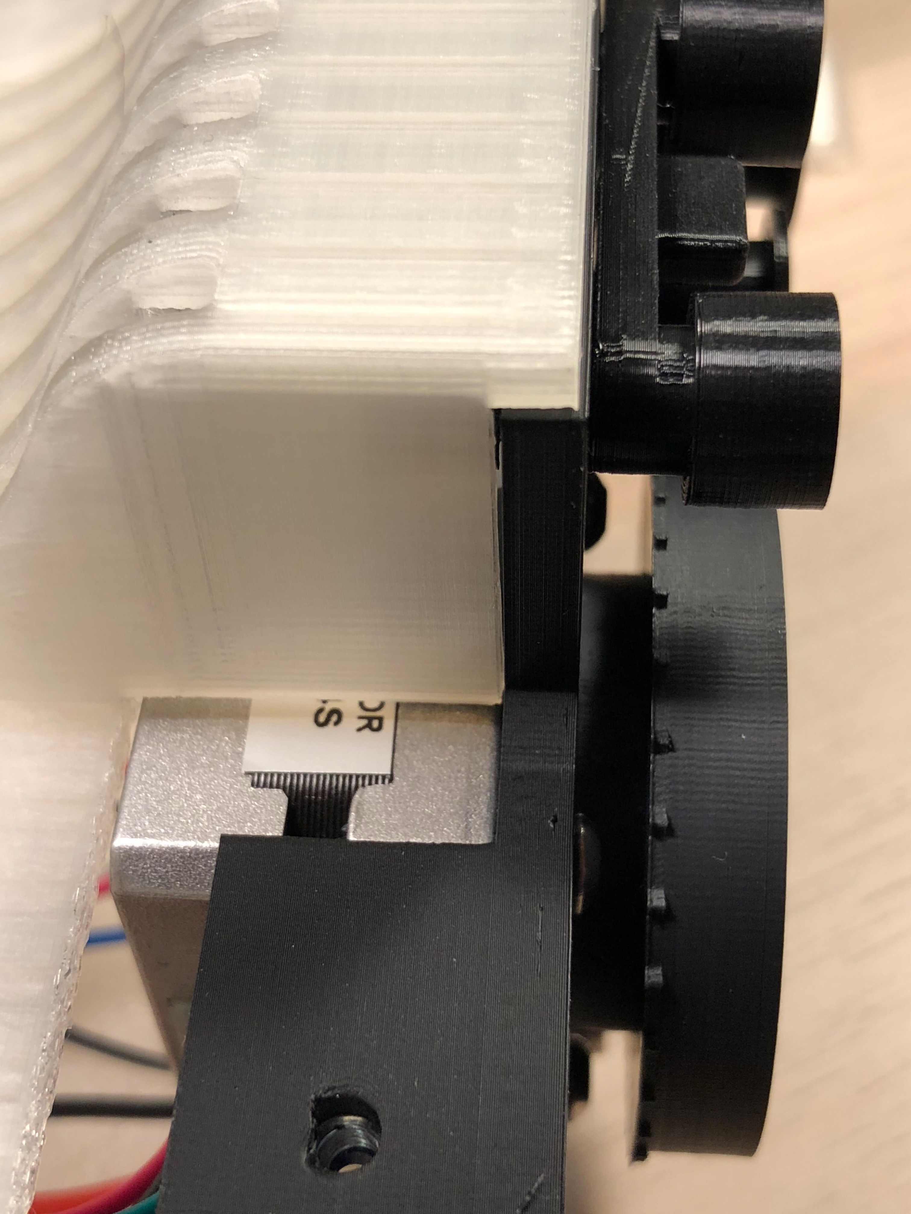
Push the sprocket back spacer on the stepper axle, a a few drops of glue onto it (the spacer - not the axle!) and push the sprocket with the shaft sleeve onto the axle.
![]()
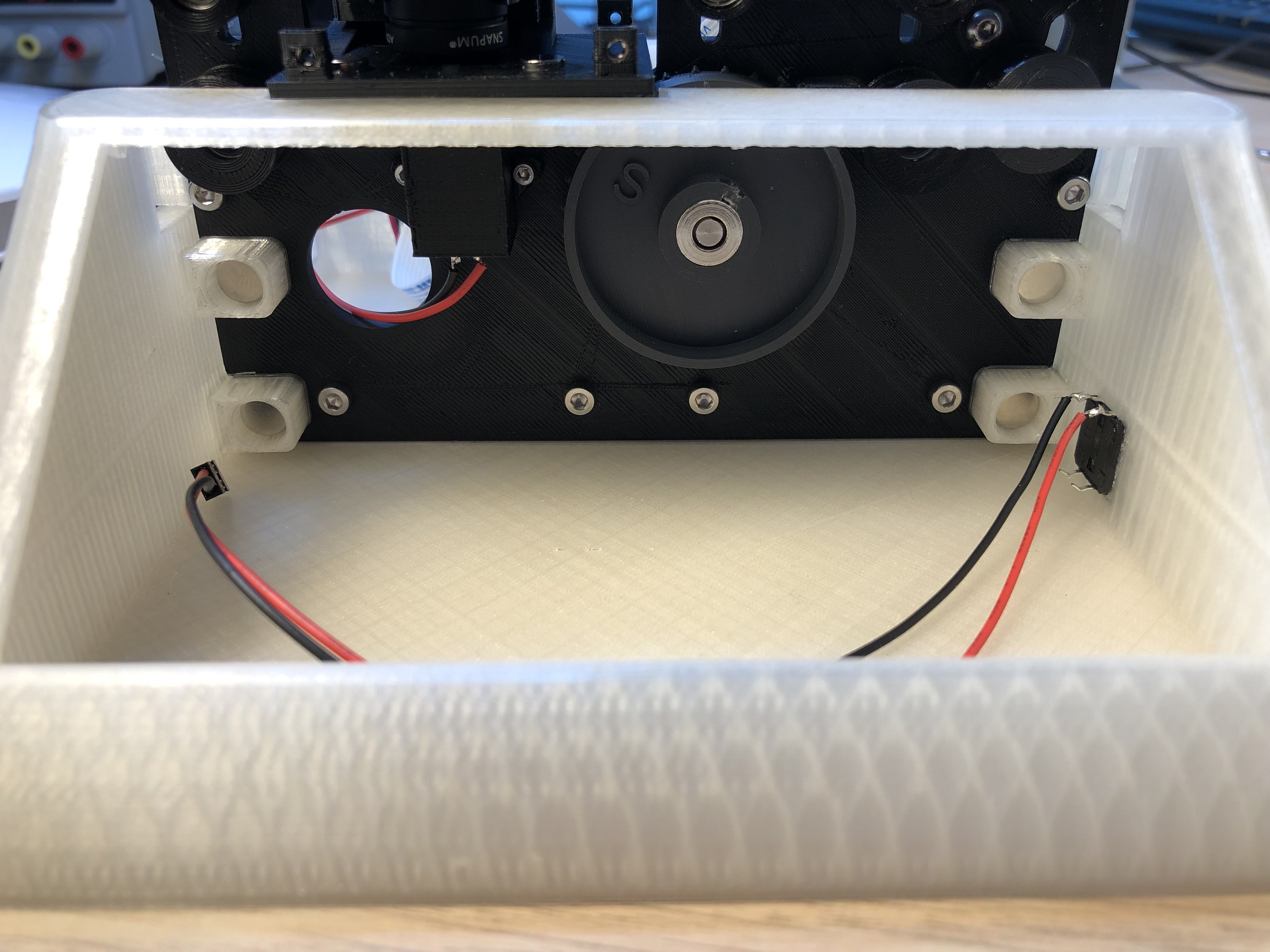
The cover should fit nicely and the magnets will hold it in place:
![]()
![]()
-
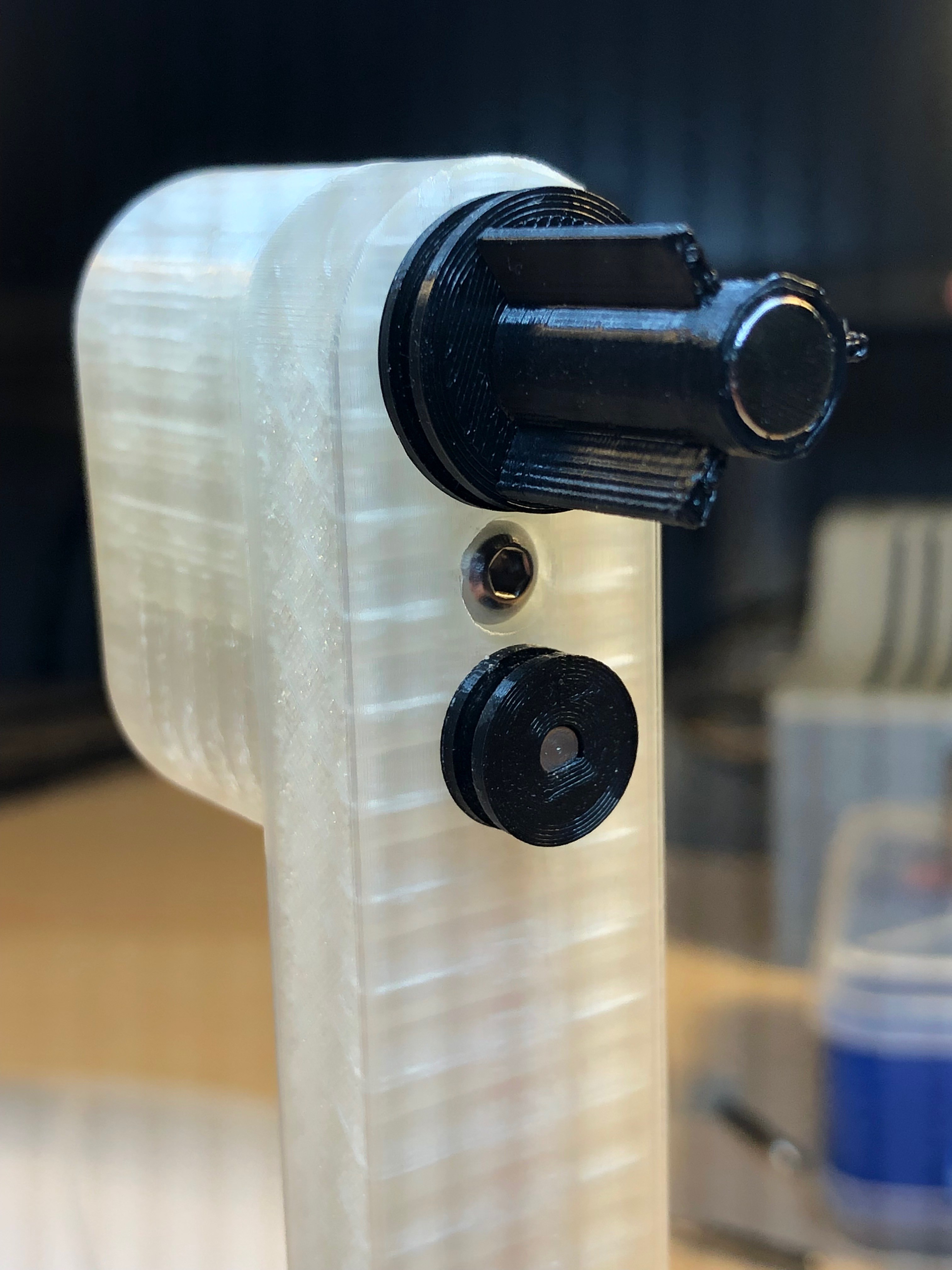
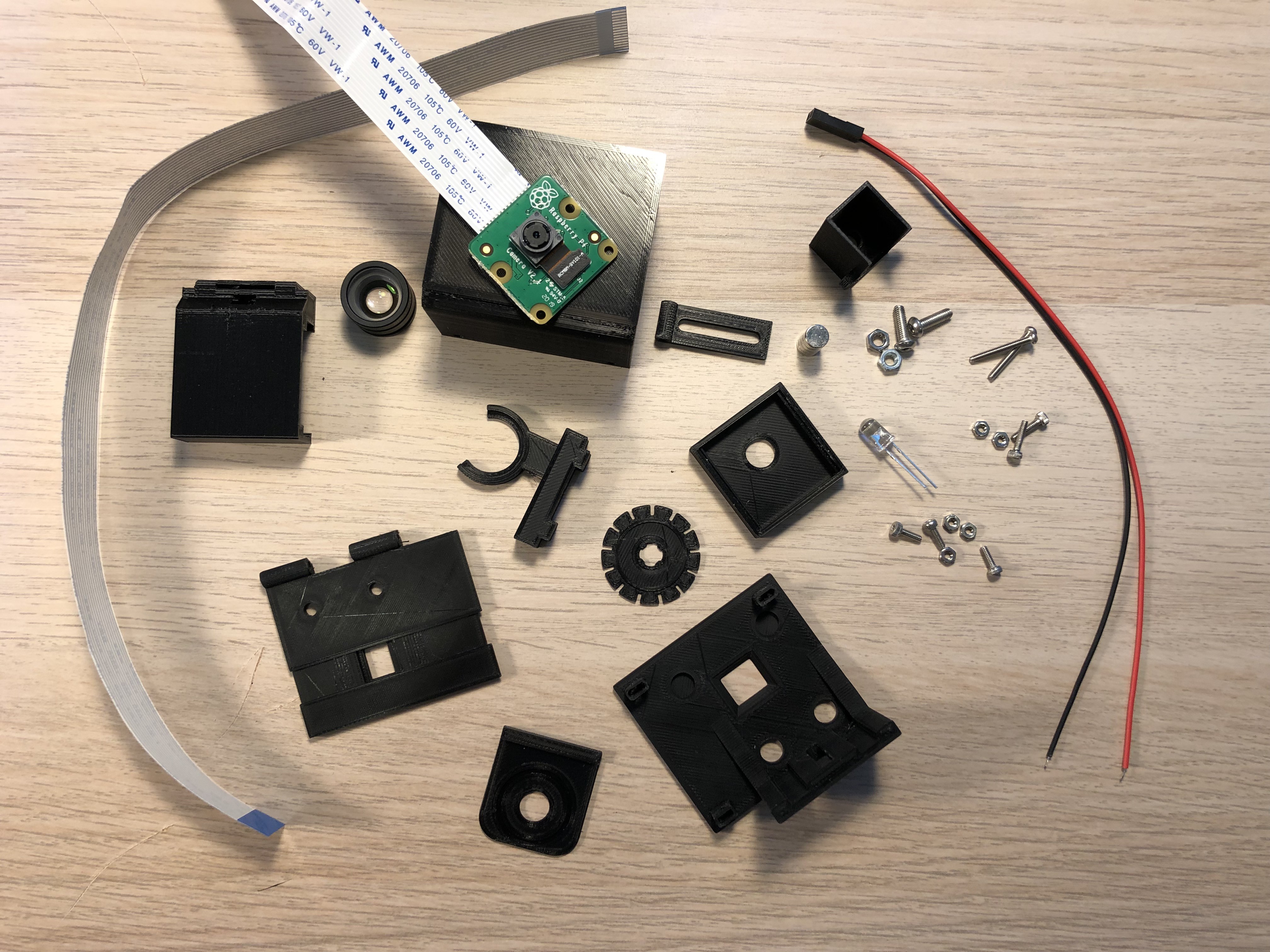
4Build and mount the camera unit
![]()
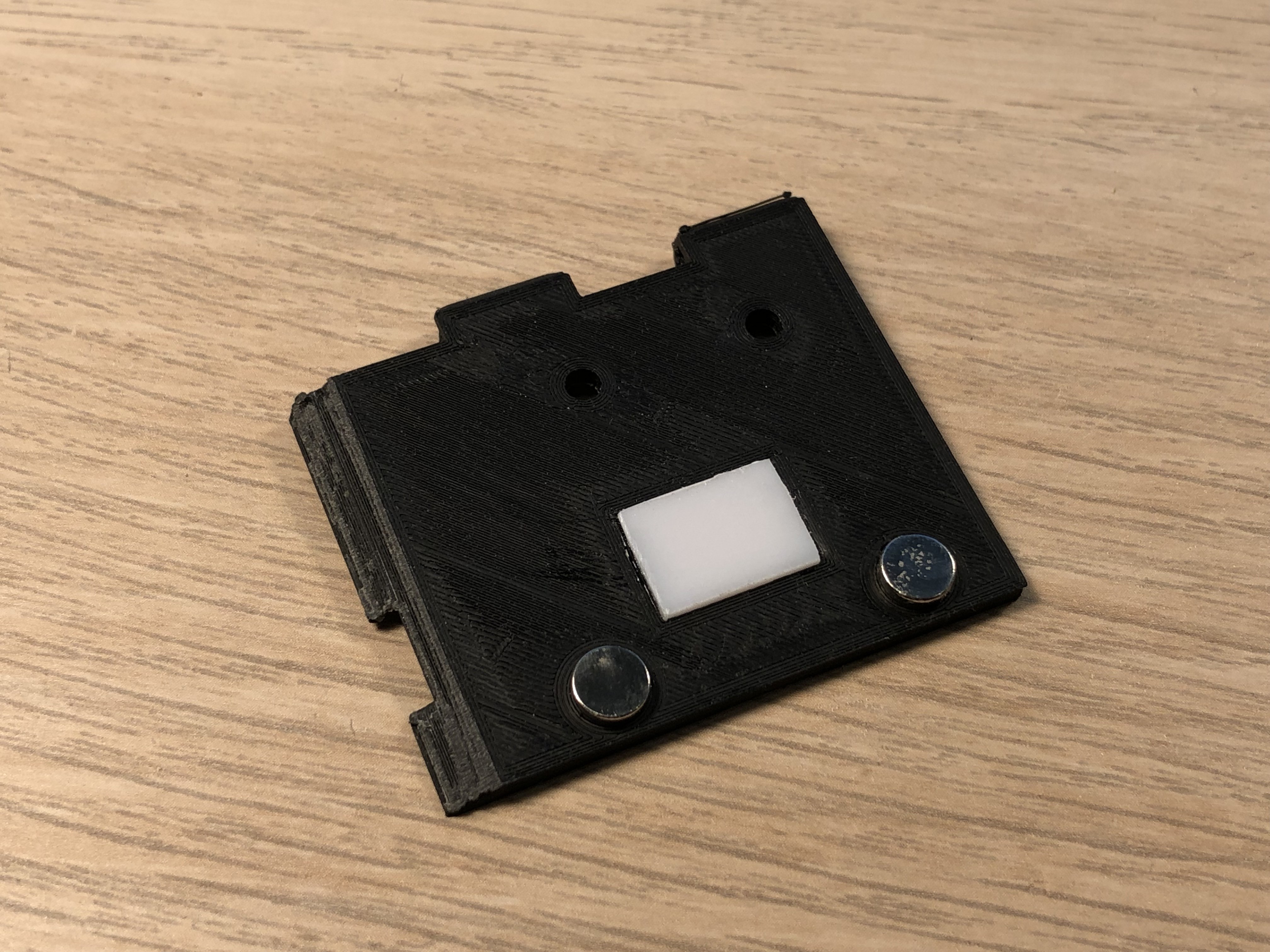
Cut a piece 10x14mm out of a 1mm acrylic sheet and glue it on the bottom of the film plate.
![]()
Also glue 2 magnets 6x3mm in place.
![]()
The film plate comes on the latch of the mount plate. Before tightening the 2 M3x8mm screws, use the adjustment tool and align the film plate exactly with the sprocket. Afterwards also align the rolls by pushing or pulling them in position. Once all parts are aligned, confirm it with an 8mm film.
![]()
Solder cables onto the LED and push it in the hole in the light box. It should sit tight, but you can secure it with a bit of glue. Mount the assembled light box under the film plate by using 2 M2x8mm screws and nuts.
![]()
Fix the film plate joint with 2 M2x20mm screws:
![]()
The screws will sit loose, so better fix them with a tiny drop of glue.
![]()
Glue 2 6x3mm magnets onto the camera mount rail. To ensure correct polarity, put the camera mount rail on the film plate.
Put 3 M2 nuts in place:
![]()
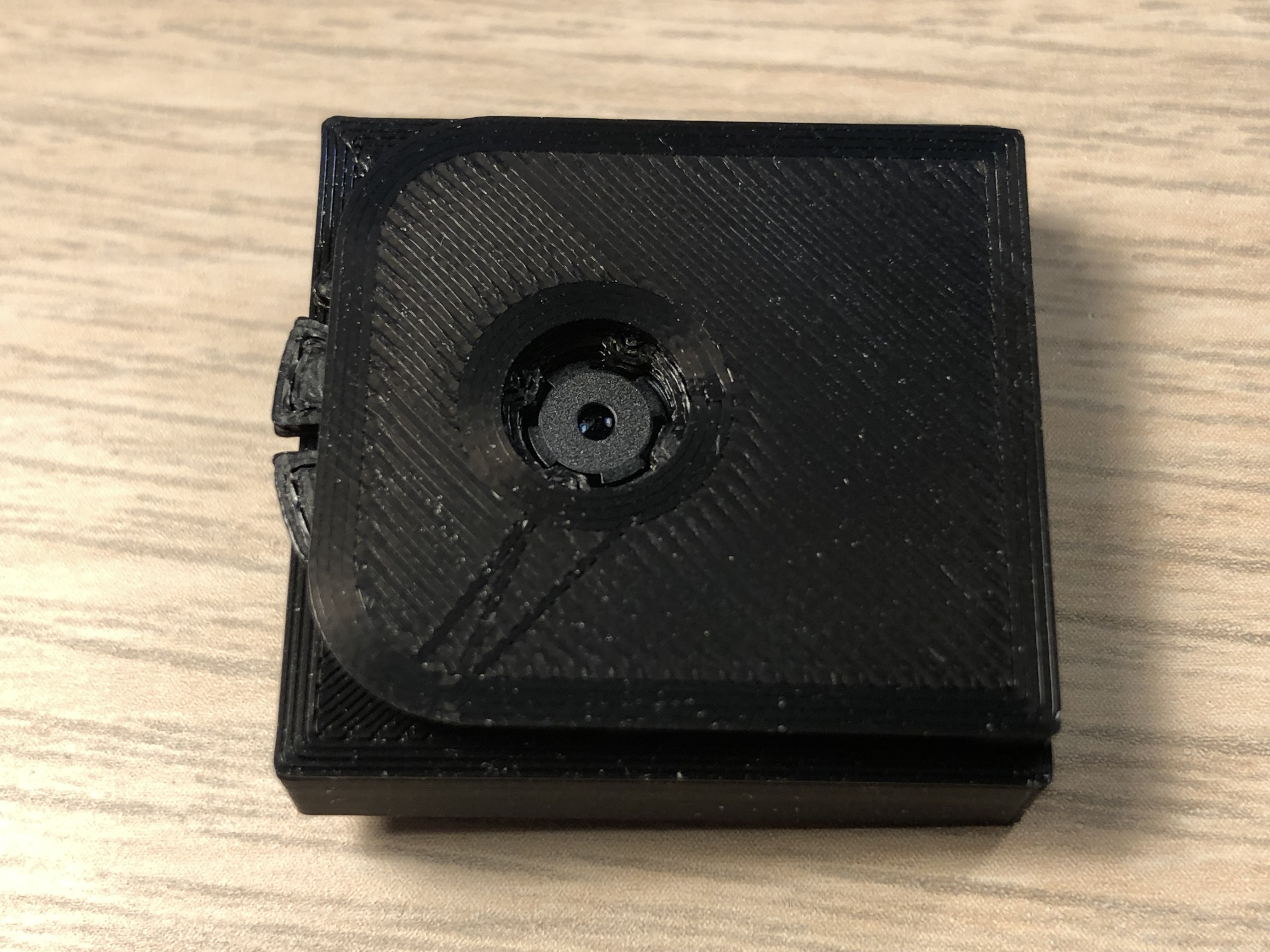
Remove the cable from the Raspberry Camera and put the camera into the camera case inside. This should be a tight fit and it should snap in place.
![]()
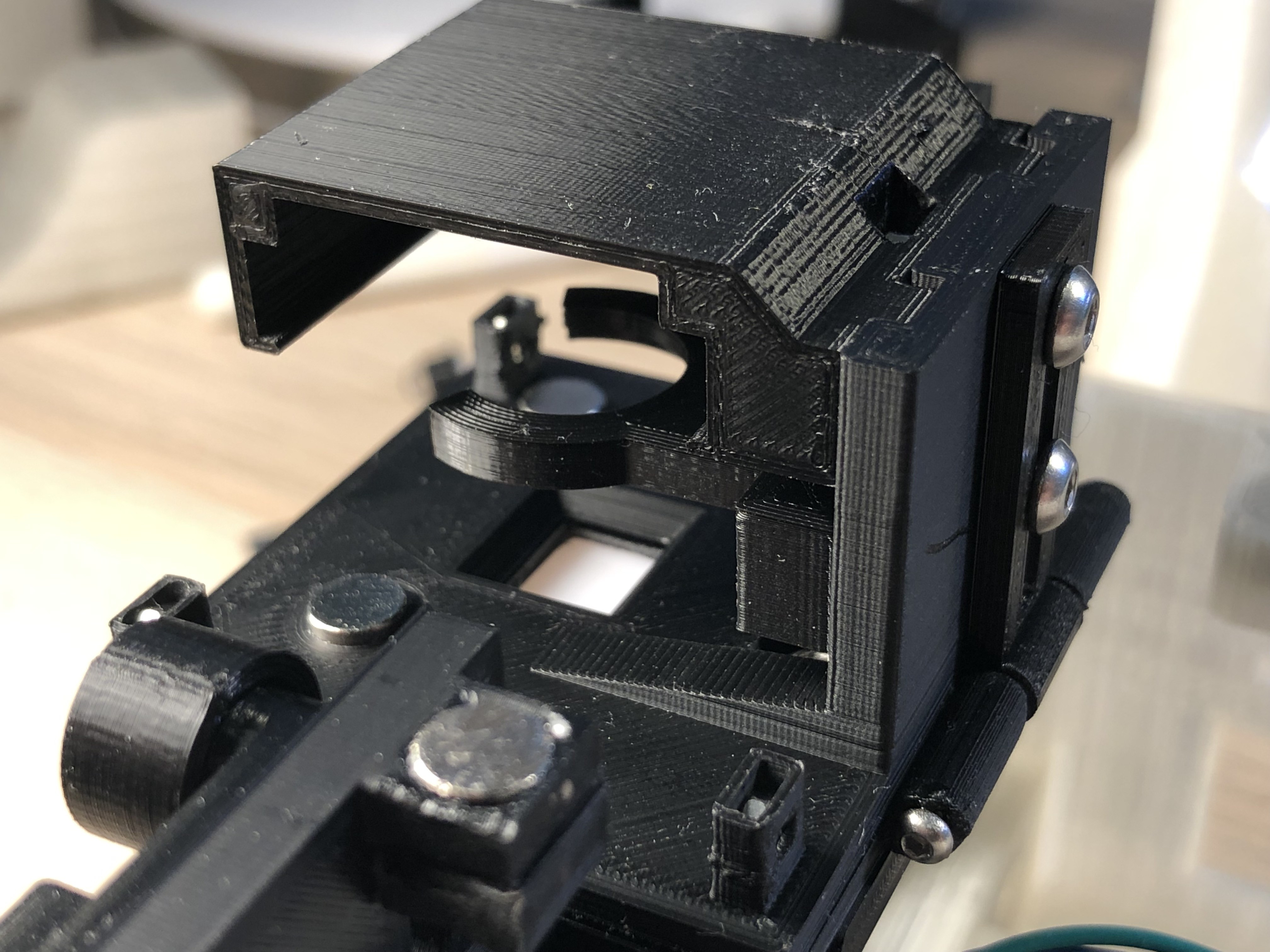
Put the camera lens adjustment tool over the lens and fix it by glueing the camera adjustment tool holder onto the camera case inside. Use only little glue! The adjustment tool must not be blocked so that you can turn the lens to focus.
![]()
Put M3 nuts into the lens holder and the camera case:
![]()
Fix the lens holder and the camera case to the camera mount rail with 2 M3x8mm screws.
![]()
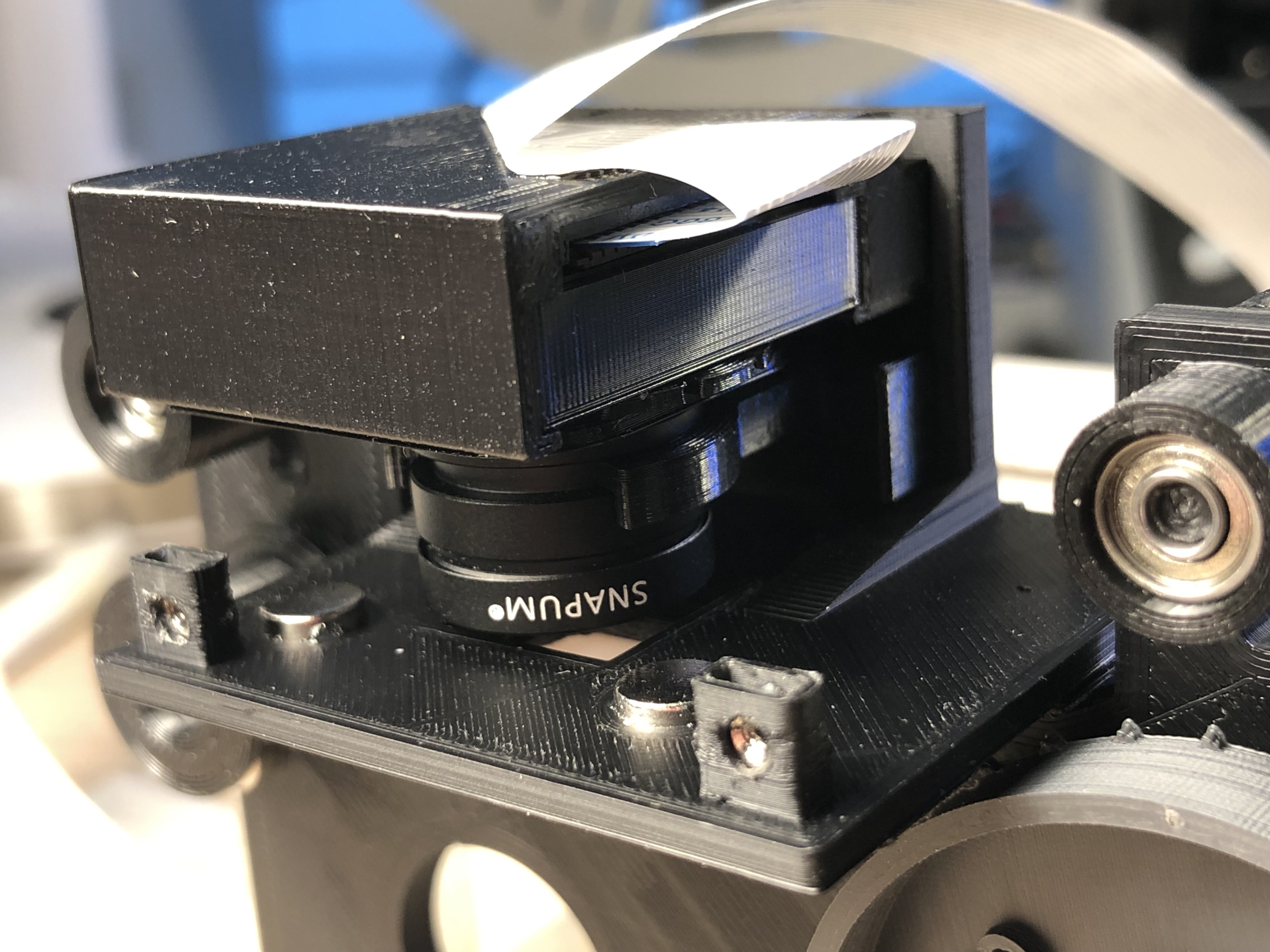
Put a cable into the Raspberry camera - the original one is too short, I'm using a 30cm long one which is longer than needed and slide the camera into the camera case.
Snap the lens into the lens holder .
![]()
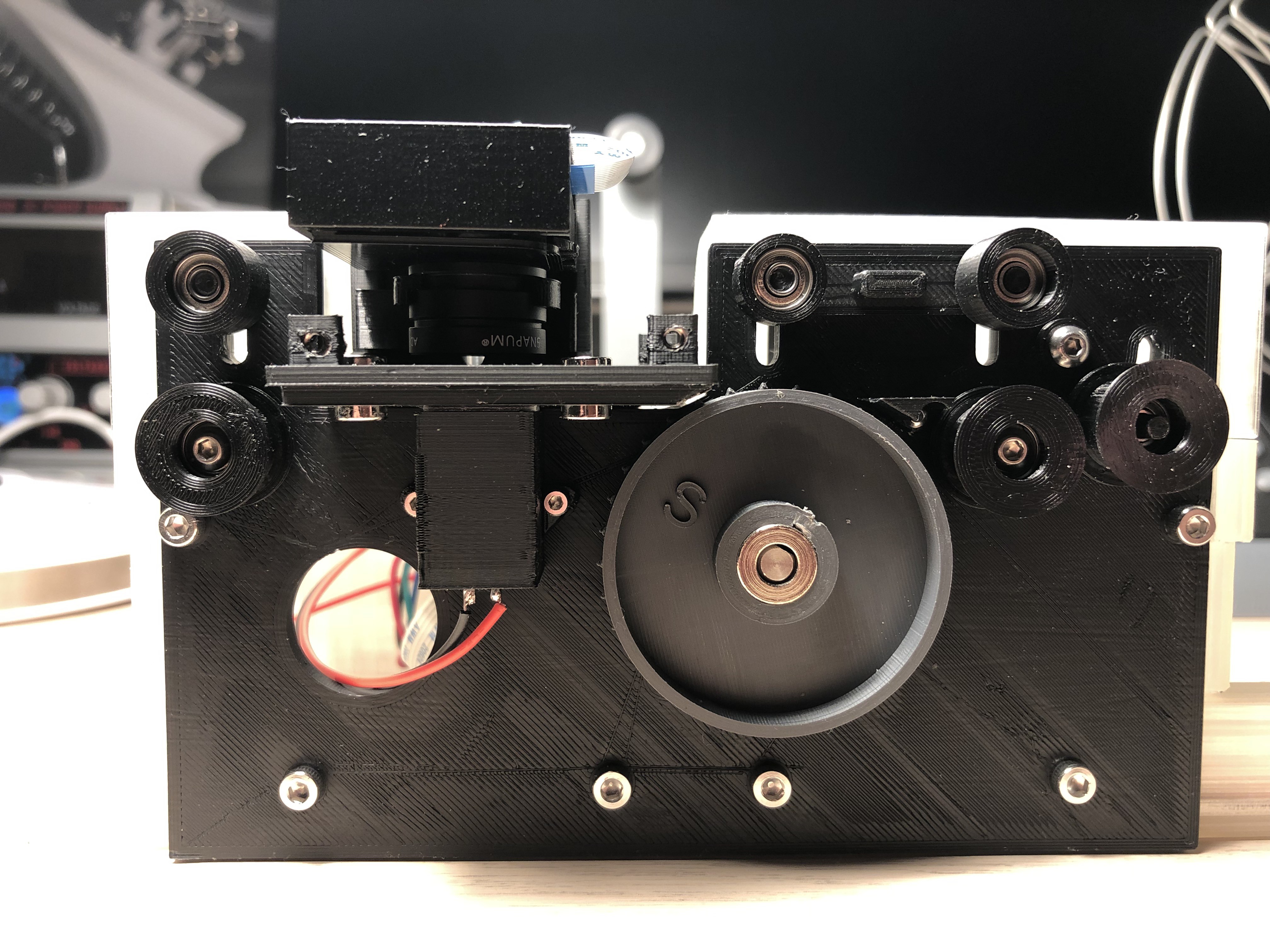
We do not need to put the camera cover on, since we still have to adjust camera and lens, but that will only happen once the software is installed.
![]()
-
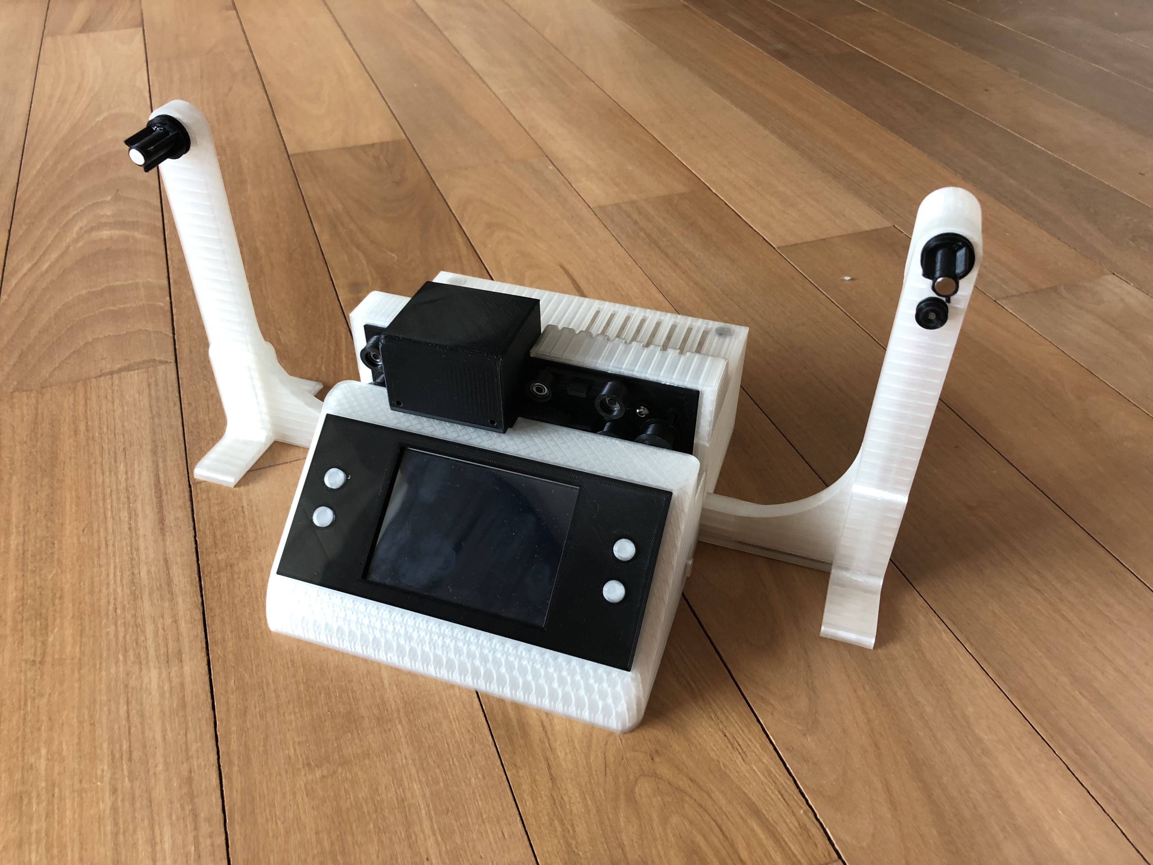
5Finishing the build
![]()
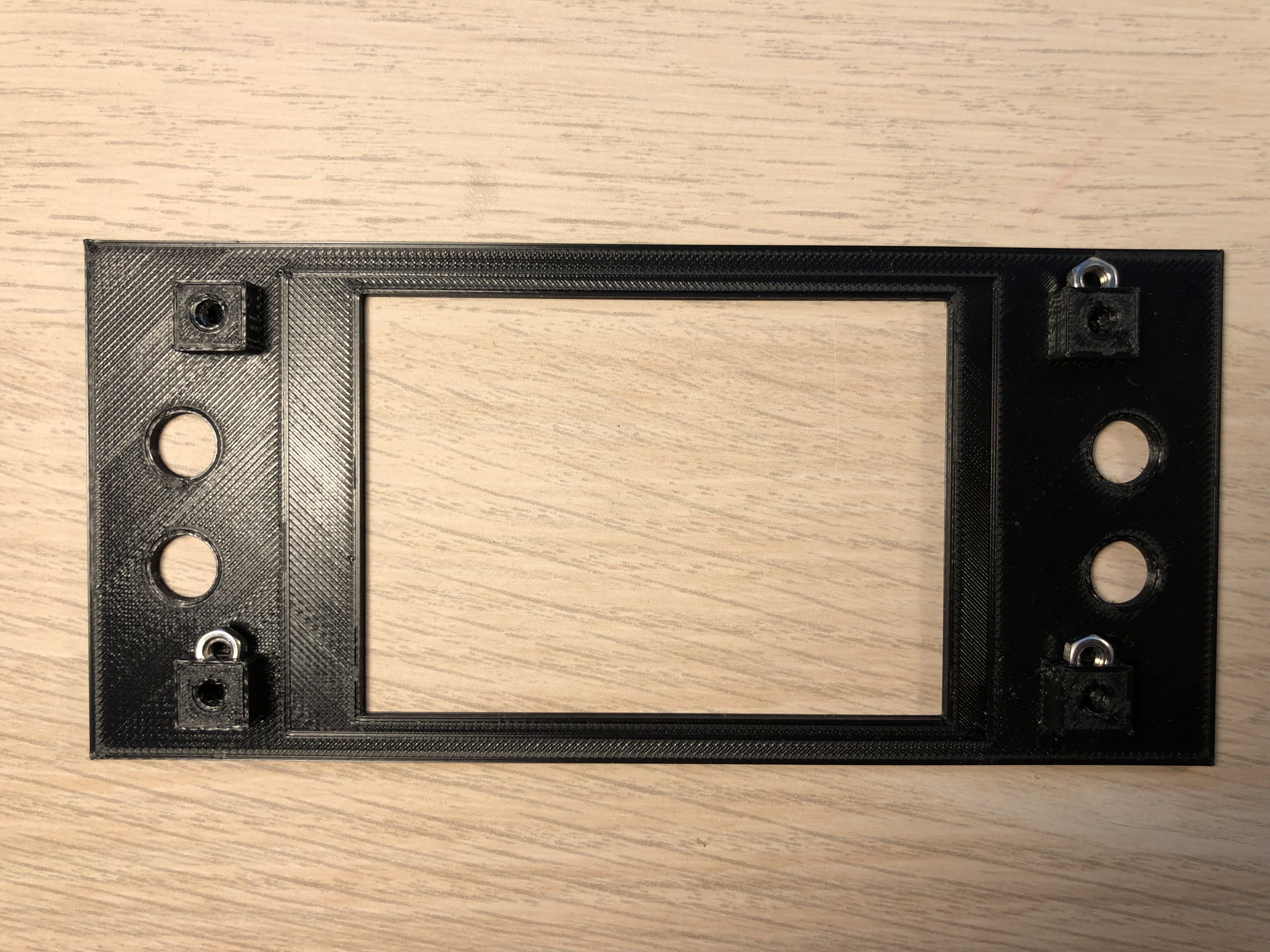
Lets start with the display: Put 4 M3 nuts in the pockets at the back of the display panel:
![]()
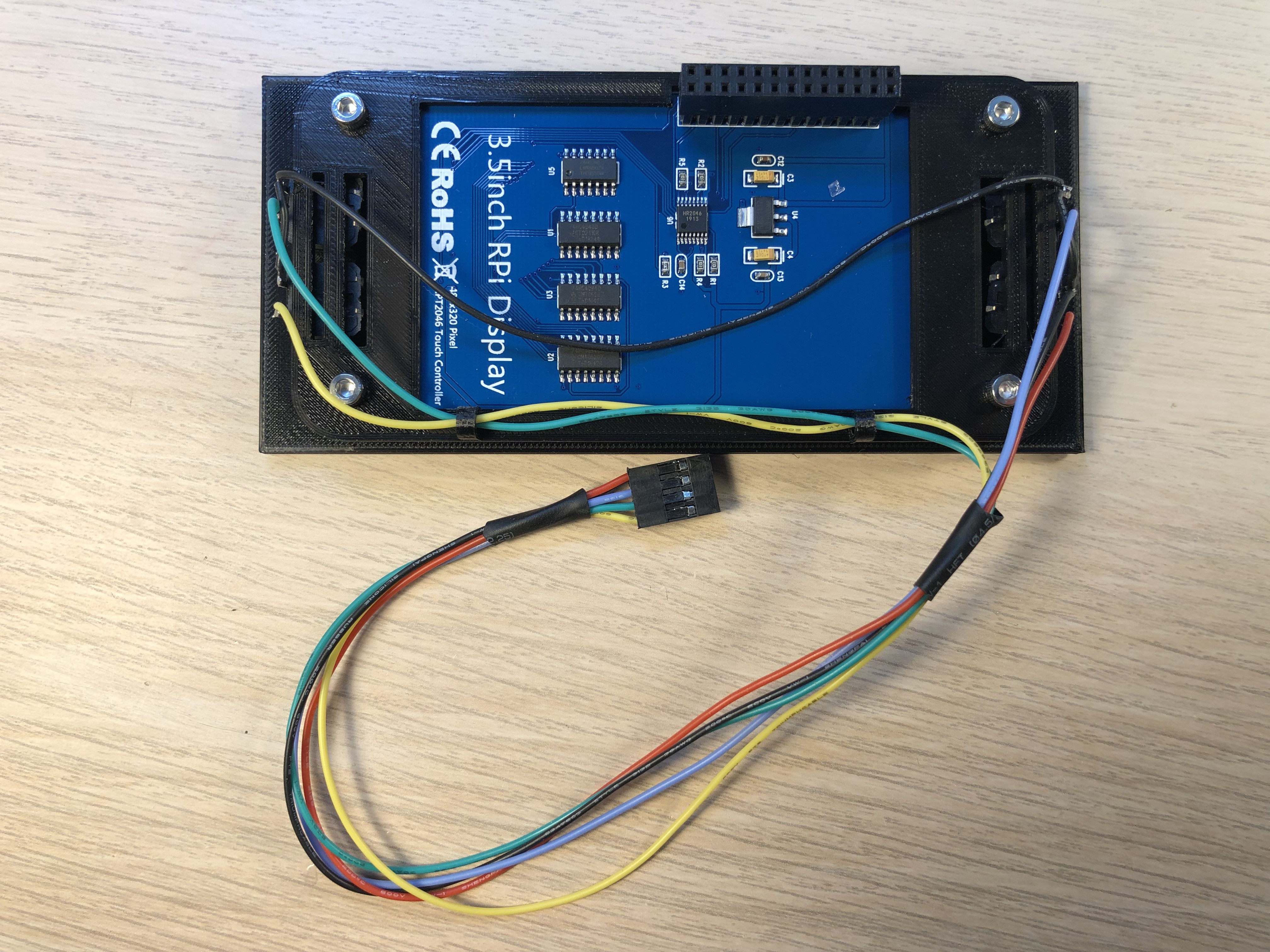
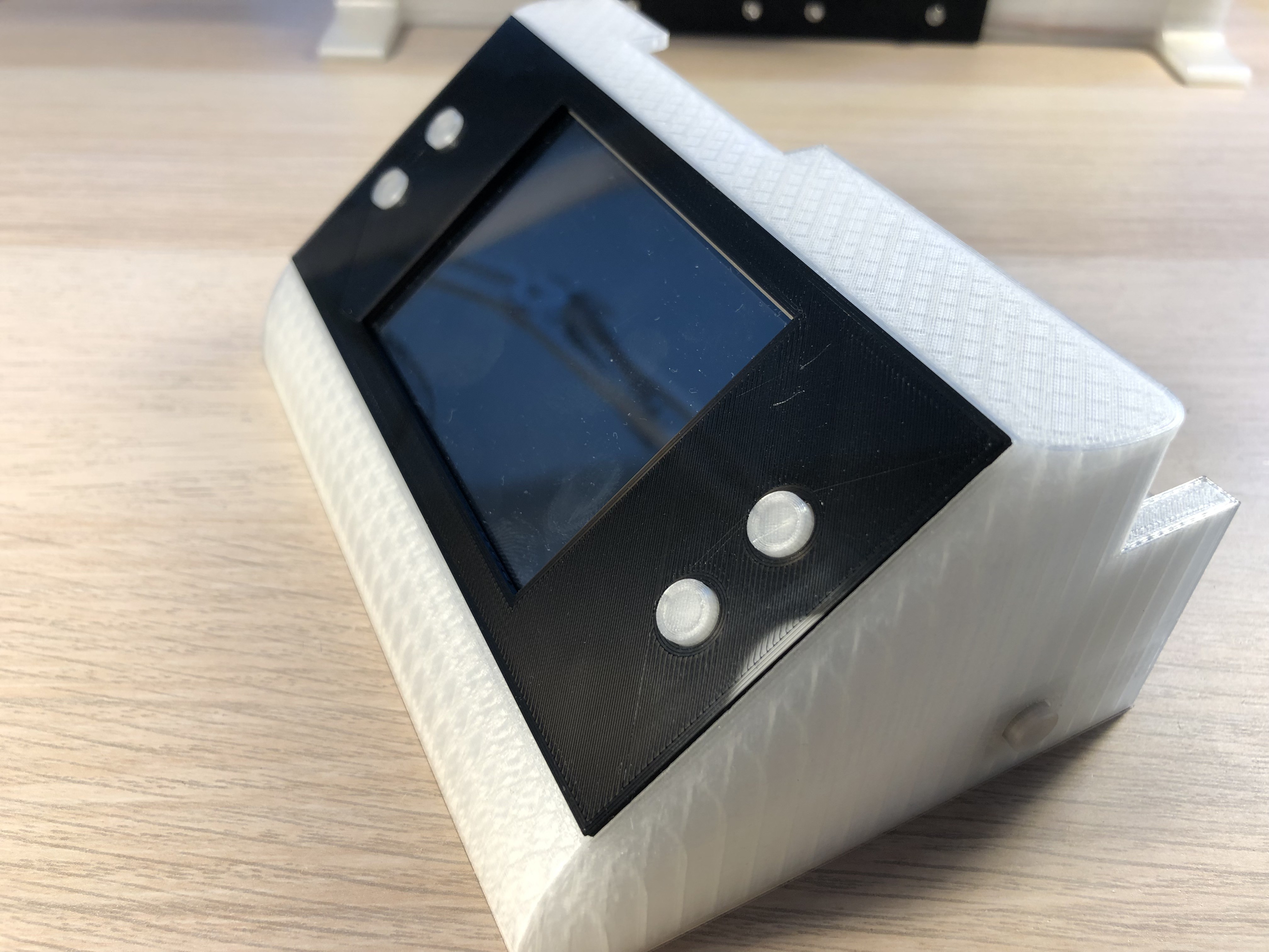
Put the 4 button caps on 4 buttons, put them through the holes in the display panel, put the 3.5 inch display onto the panel and fix buttons and display with the display frame using 4 M3x6mm screws.
![]()
Connect one pin each button together for the GND line and one cable each button for the signal.
![]()
I created a hat for the electronics, therefore I have to ensure the the buttons get connected to the correct pins. If you create your own PCB just adjust the plug accordingly.
![]()
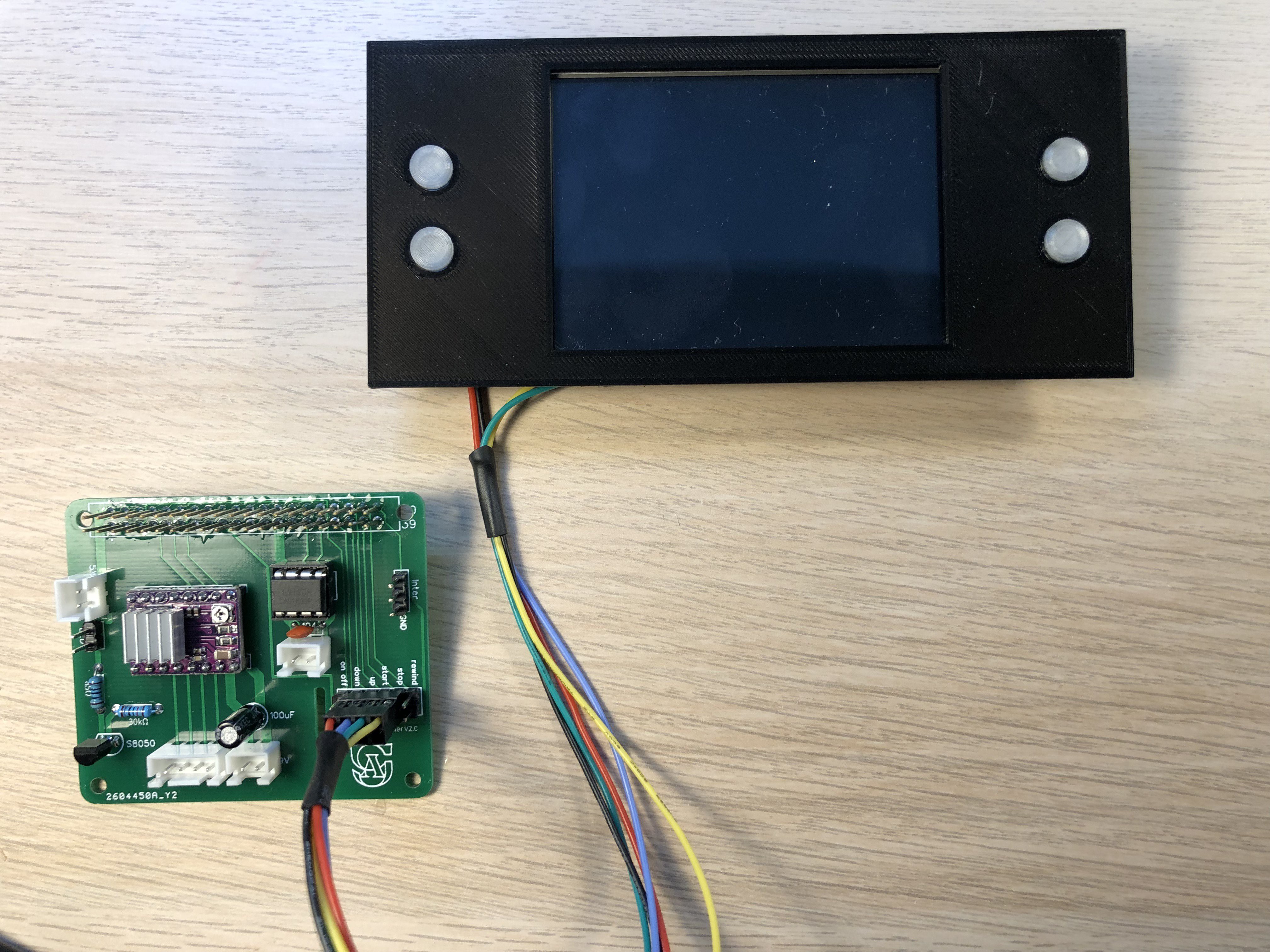
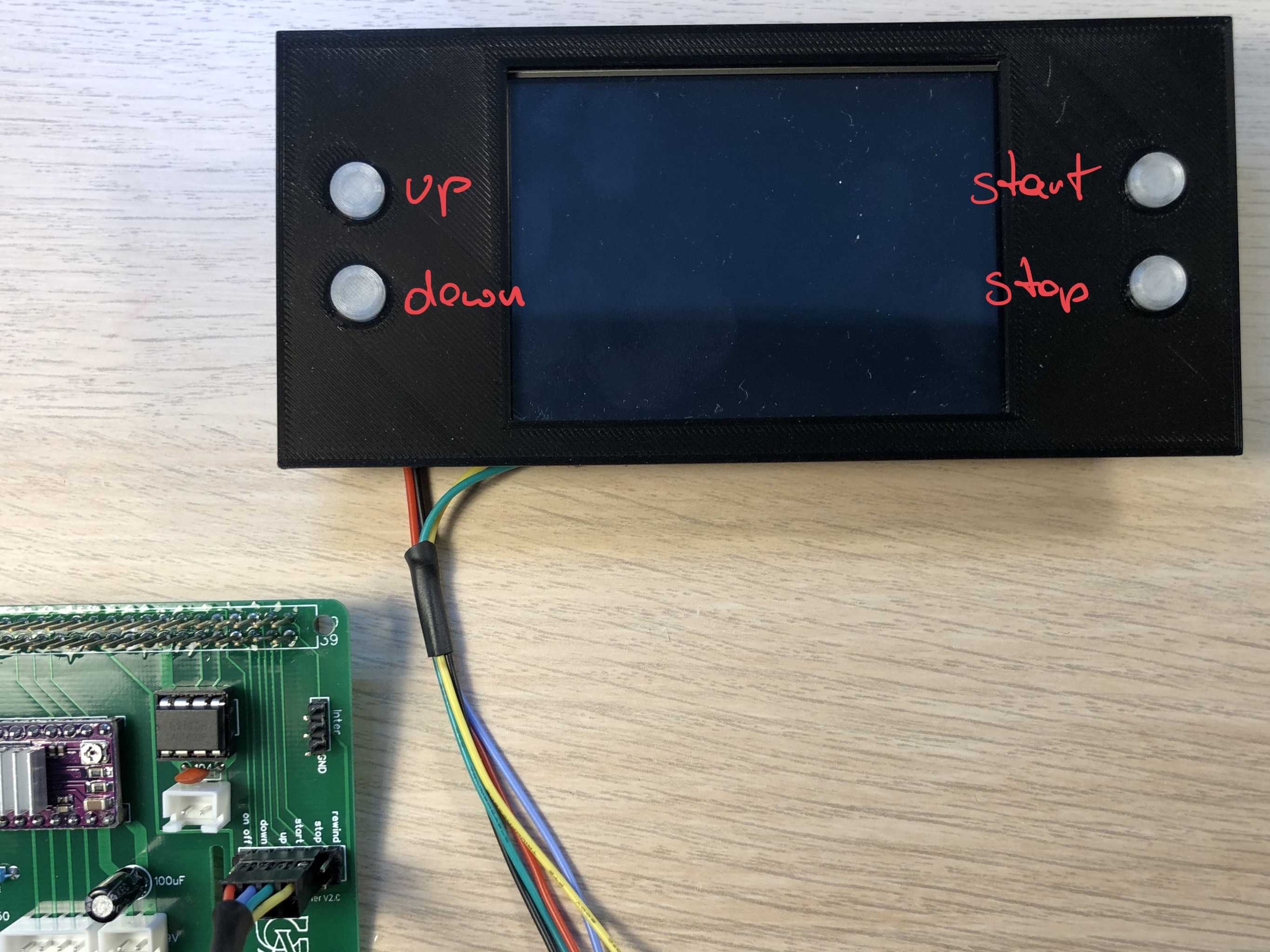
Naming of the buttons:
![]()
Push a button with cap into the hole at the side of the front case:
![]()
Glue magnets (8x5mm) into 4 magnet holders. To ensure correct polarity, stick them onto the mount plate:
![]()
Put the front case in place, put some glue onto the sides of the magnet holders and put them onto the mount plate. Push them to the sides so that they get glued to the front case. Once the glue cured, you can detach the front case by pulling.
![]()
Put the display in the front case:
![]()
![]()
Congrats! that concludes the assembly of the hardware.
In the next steps we will put all the electronics together, configure the Raspi, install all necessary software and calibrate the camera.
![]()
-
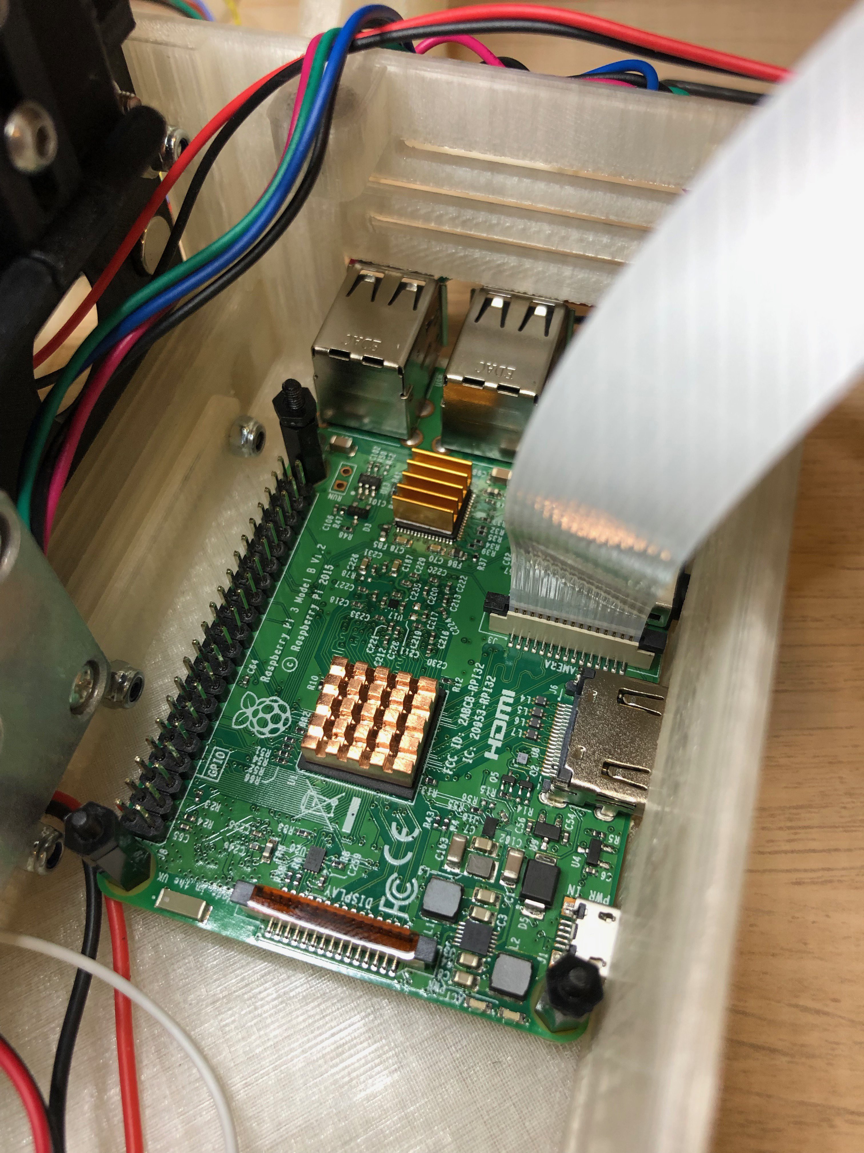
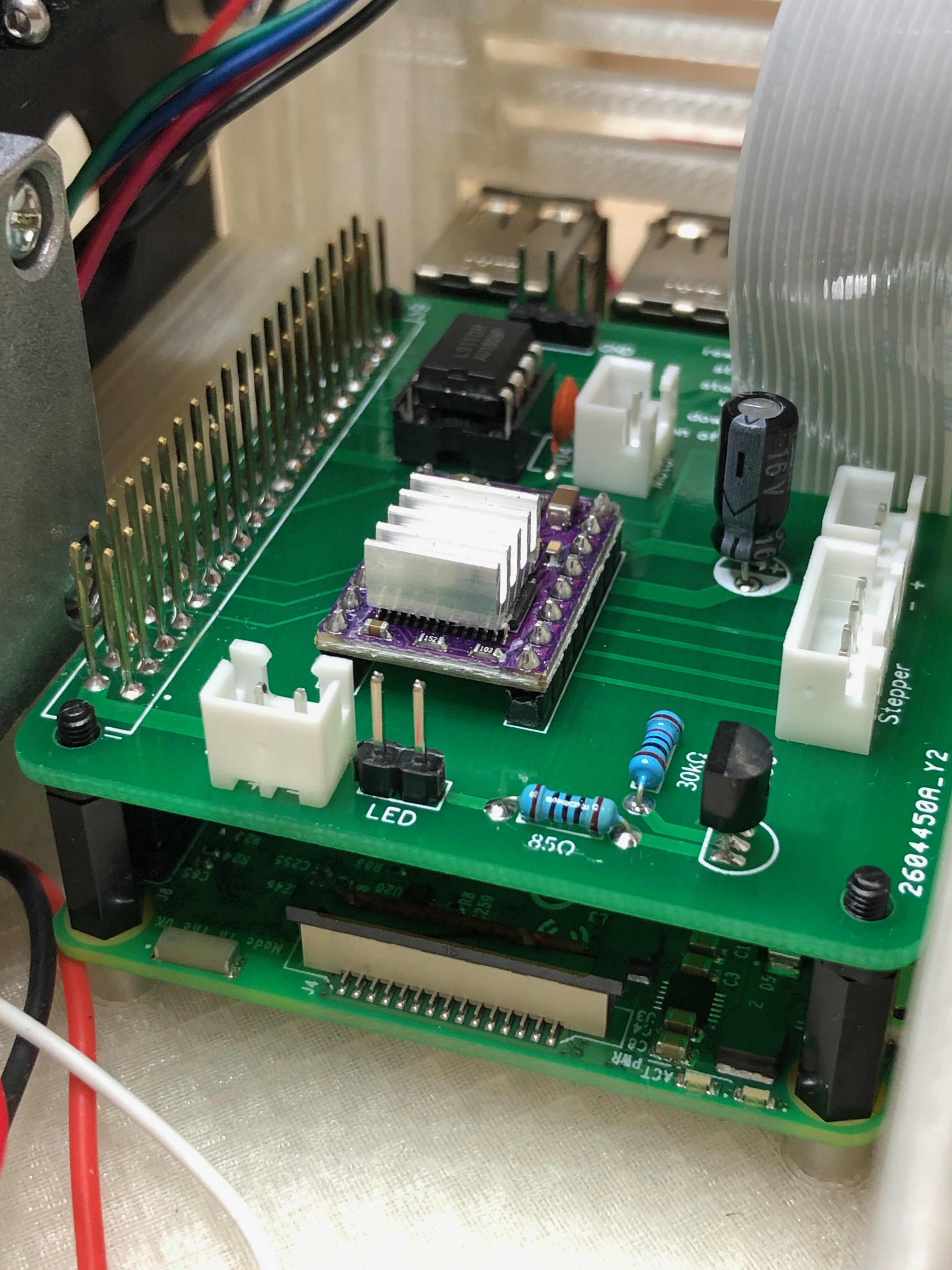
6Installing the electronics
You should put heat sinks on the Pi.
Now mount the Raspi with the camera cable connected, using stand offs (if you mount a hat) and screws.
![]()
In my case I mount the hat - with a stacking header, so I can connect the cable from the 3.5 inch display.
![]()
The display is designed to stack it directly onto the Pi's pins. Since that is not possible in our case, we need to connect it to the pins with a cable. We do not need all pins - so this are the ones I connect:
![]()
To power the film copier we need to different voltages: abt 9 V for the stepper and 5 for the Raspi. I'm using a step down converter that supports a max of 3A.
Connect the power jack with the converter (in) and add another cable to power the stepper.
Add a cable to the converter output - do not connect it to the circuit yet!
![]()
Also - do not yet connect the stepper motor.
All other connections, the LED, the interruptor, the buttons and the spool motor should be done now.
![]()
You can now connect the 9V power adaptor (3A).
Now take a multimeter and measure the "out" pins of the step down converter. Adjust to 5V.
Only connect the Power to the Raspberry Pi once its at stable 5V! I designed that hat in a way that the 5V go through the pins - so there is no protection.
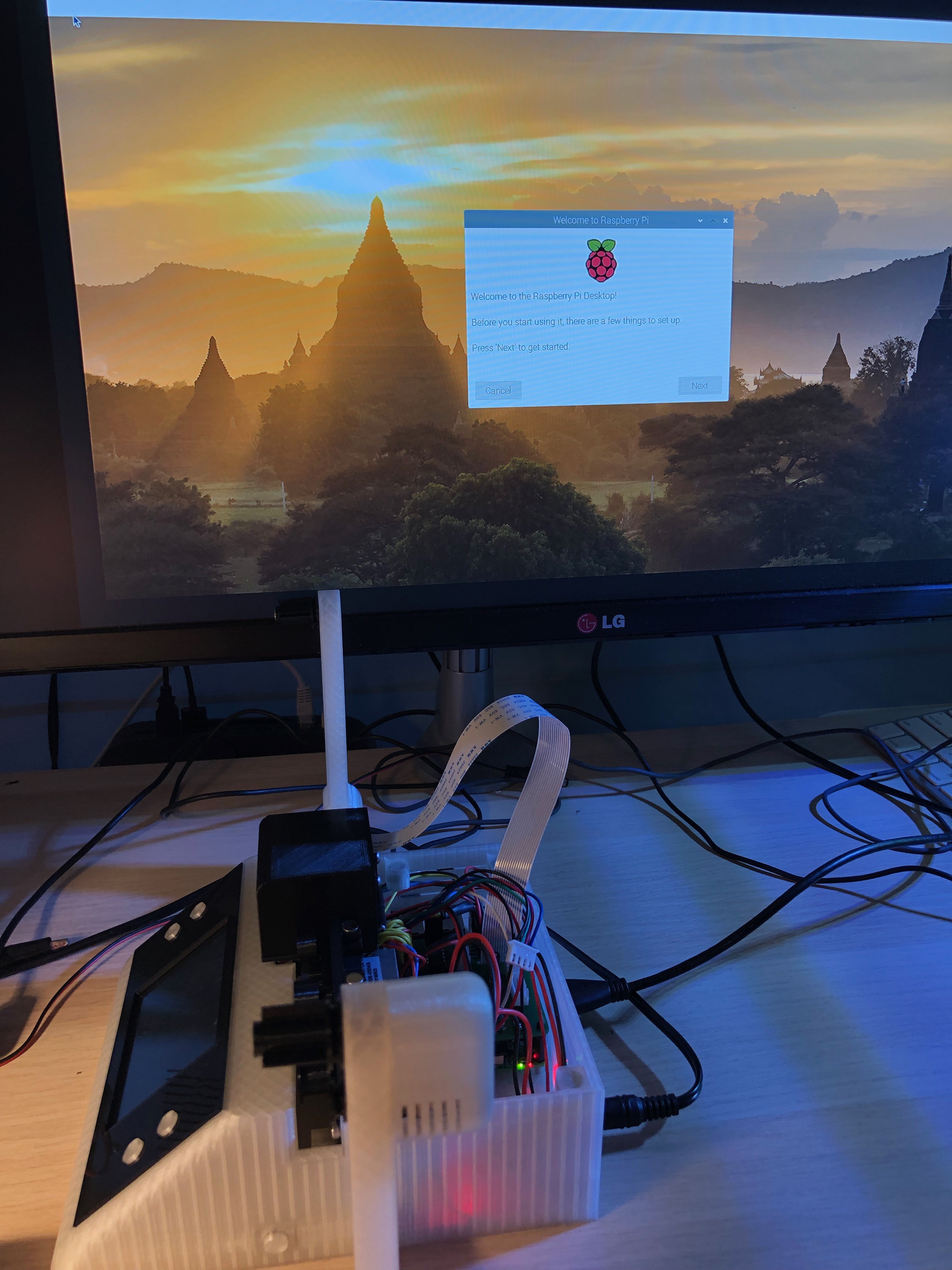
Its time to get the Raspi up and running. Connect Keyboard, mouse and monitor. (we need it for the installation)
Download the latest Raspbian version and install it onto an SD card. I'm using 128GB - so that there is enough space for the film projects. Put the SD card into the Raspberry and connect the (5V) power.
The system will now boot and ask for some information:
![]()
After the routine setup, activate the camera under "Interfaces" in the Raspi configuration.
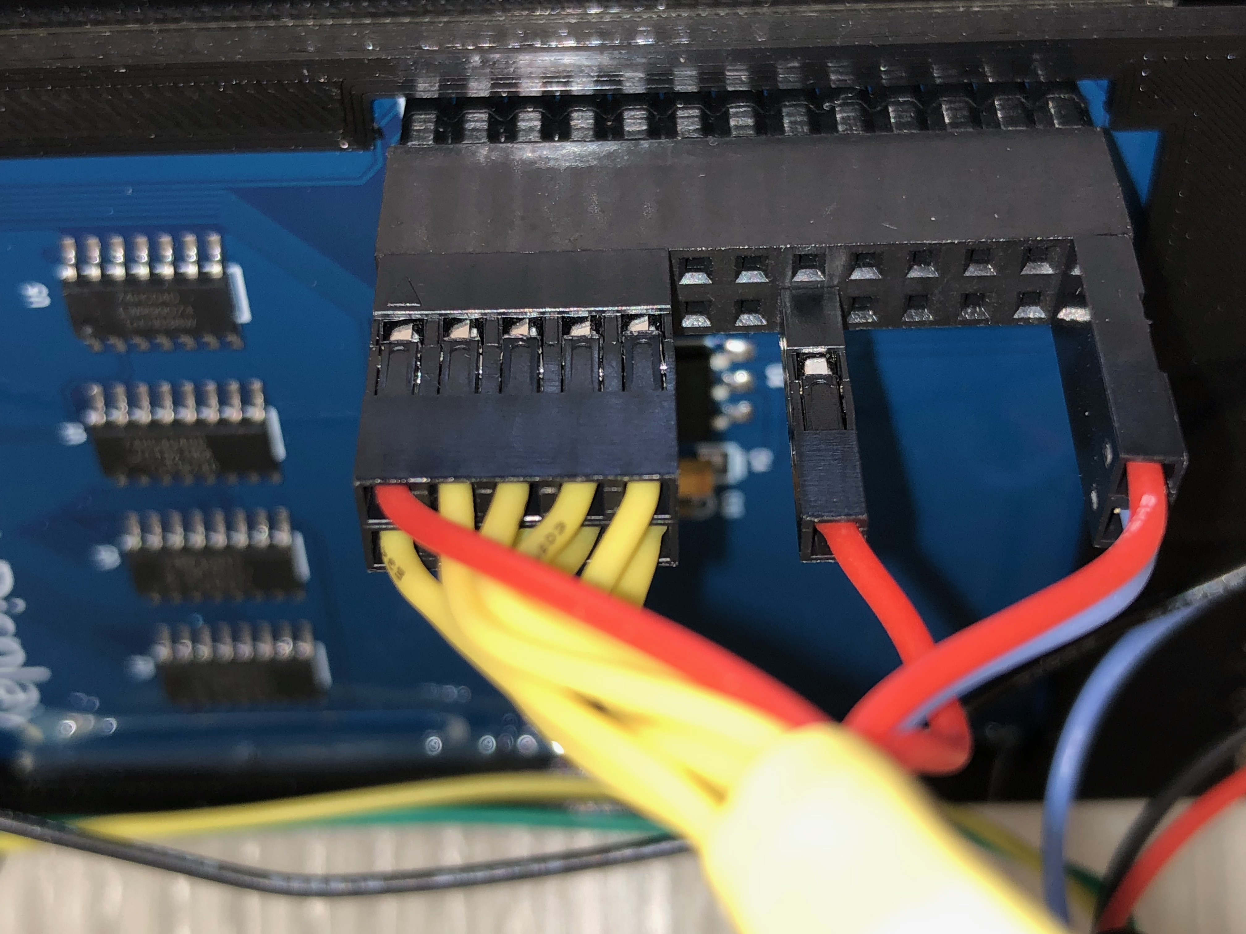
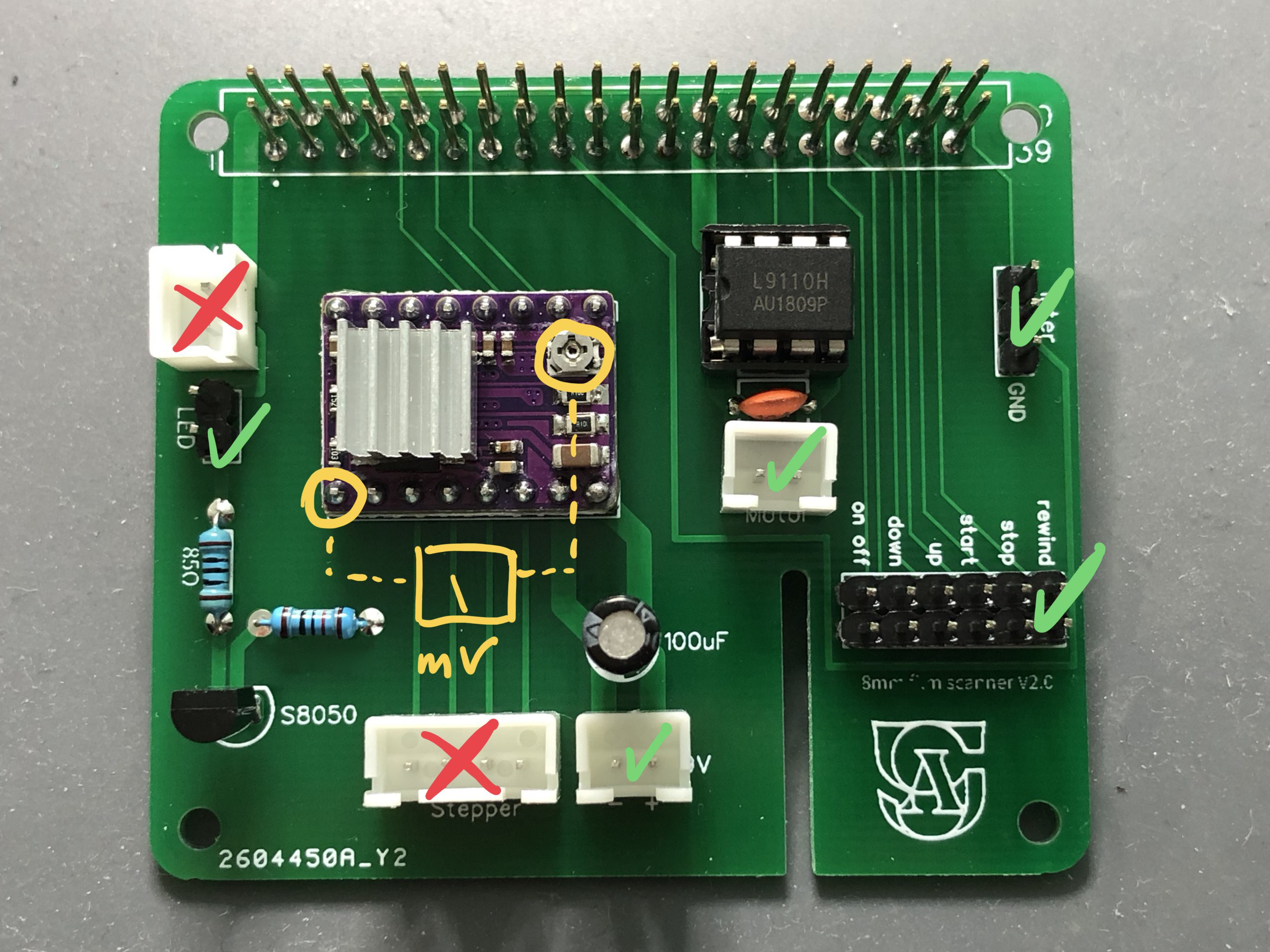
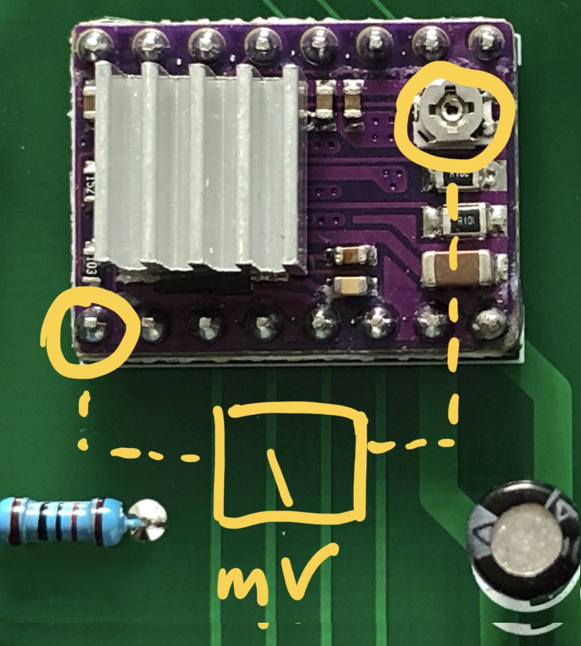
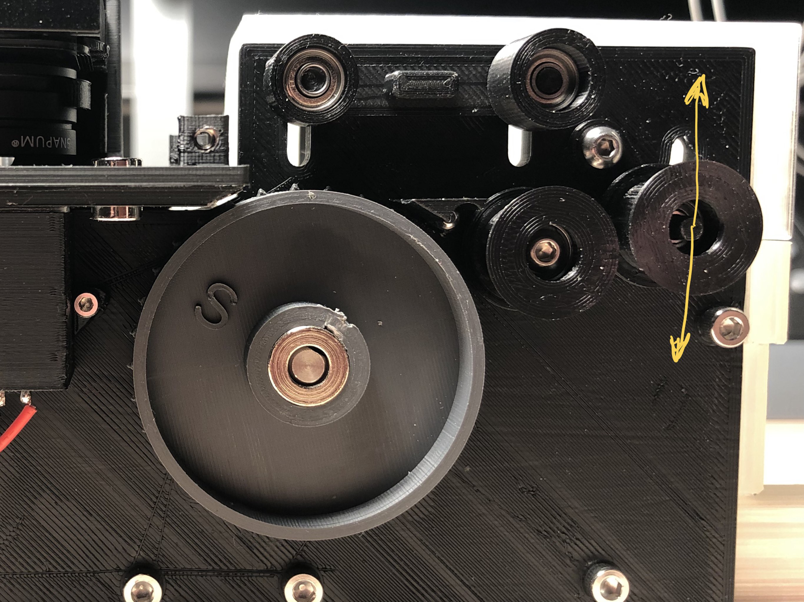
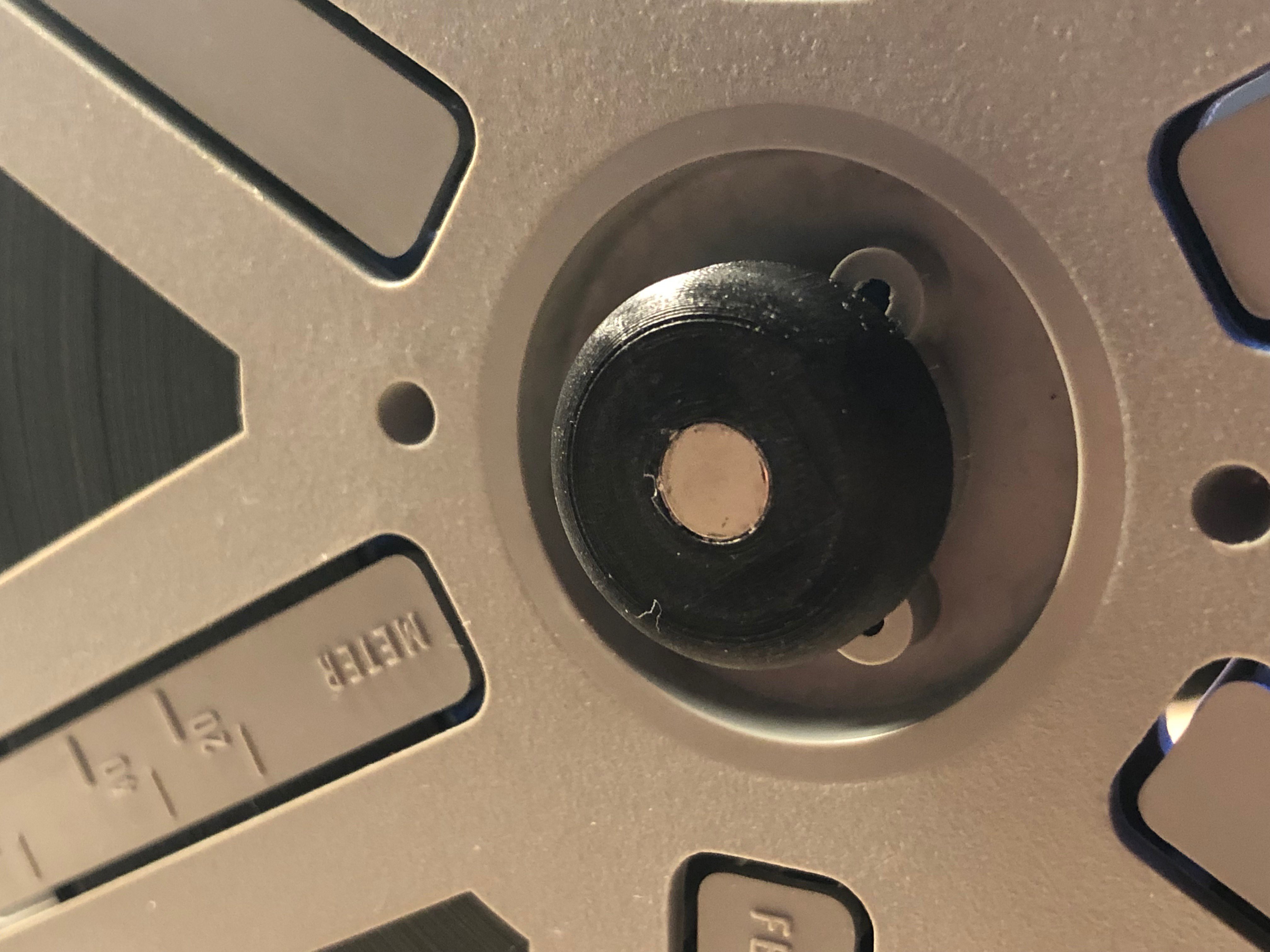
Now its time to adjust the Vref on the stepper motor driver:
![]()
This will limit the mA to the stepper. The motor I'm using is rated 0.5A, so I adjust the Vref to .25 Volts.
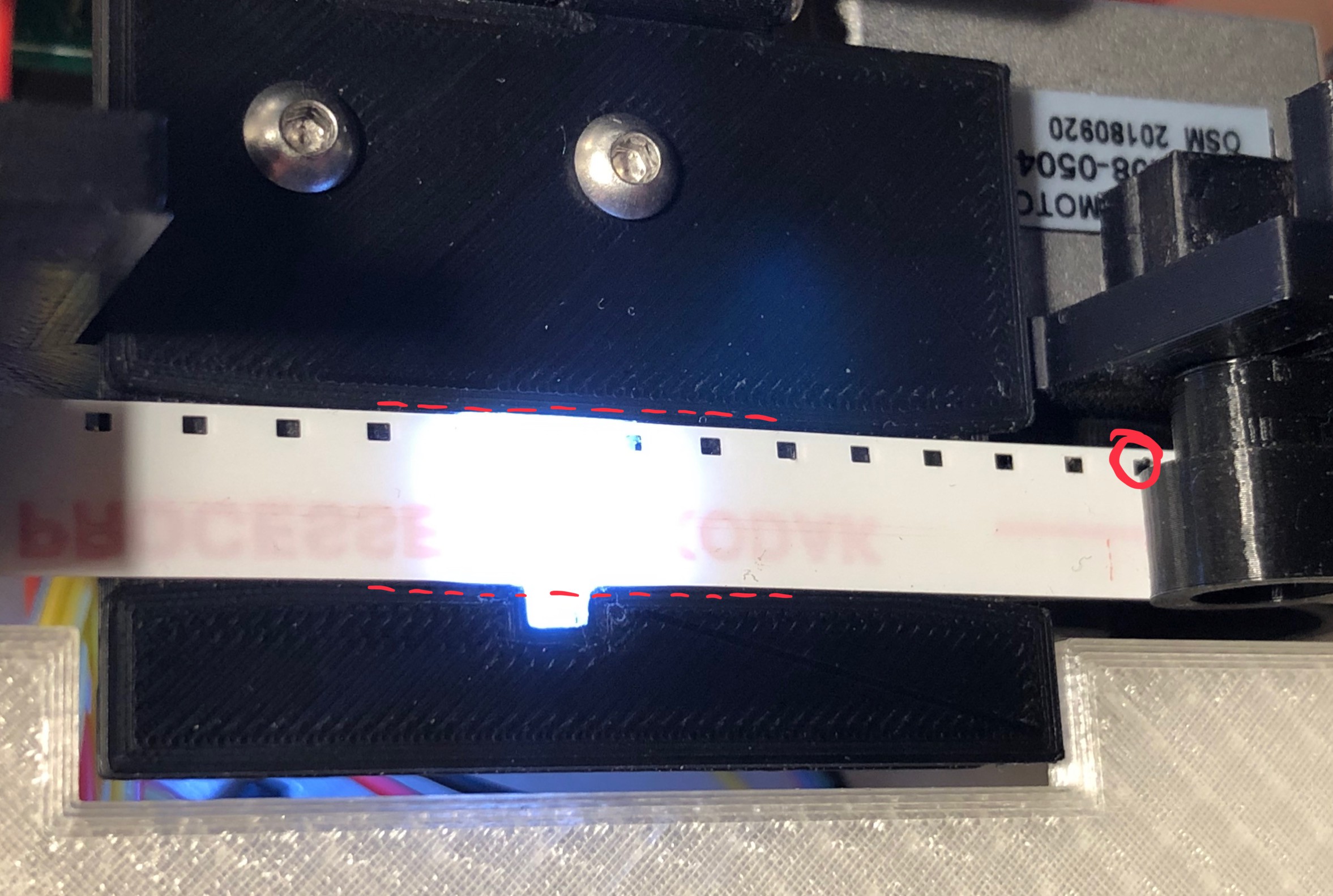
If you use my schematic, the driver is connected to a pin that allows turning it on and off. To adjust the Vref the driver has to be on. Therefore run the S8_test.py script.
Just use a multimeter and connect it to the GND on the driver (the left yellow circle on the picture) and measure and adjust the voltage where you can see the right yellow circle.
If you want to learn more about that - I recommend the tutorial from rototron:
https://www.rototron.info/raspberry-pi-stepper-motor-tutorial/
I find all his tutorials super clear and useful - take a look!
Once the Vref is adjusted, turn off your Raspi, connect the stepper to the board and start it again. We are now ready to test the functions necessary for the film scanner.
#!/usr/bin/env python
# This script helps to test the basic funtions of the 8mm film scanner

import time
import datetime
import RPi.GPIO as GPIO
from picamera import PiCamera
from time import sleep


DIR = 27   # Direction GPIO Pin
STEP = 22  # Step GPIO Pin
CW = 1     # Clockwise Rotation
CCW = 0    # Counterclockwise Rotation
MODE = (18, 15, 14)   # Microstep Resolution GPIO Pins
STEPON = 0 # pin to turn on/off the stepper
BtnLeft = 13    # buttons
BtnRight = 19
BtnStart = 16
BtnStop = 26
BtnRew = 20
Photoint = 21 # photointeruptor
ledon = 12 # pin for LED
pinForward = 6 #motor pin (spool)
pinBackward = 5
step_count = 100 # steps per frame (S8)
delay = .001 # delay inbetween steps
r = 0 # button repeat counter

#camera settings:
camera = PiCamera()
camera.sensor_mode=6
camera.rotation = 180
camera.resolution = (2048,1536)
##camera.awb_mode = 'off'
##camera.awb_gains = [1.8, 1.1]

#stepper mode:
RESOLUTION = {'Full': (0, 0, 0),
              'Half': (1, 0, 0),
              '1/4': (0, 1, 0),
              '1/8': (1, 1, 0),
              '1/16': (0, 0, 1),
              '1/32': (1, 0, 1)}


GPIO.setmode(GPIO.BCM)
GPIO.setup(DIR, GPIO.OUT)
GPIO.setup(STEP, GPIO.OUT)
GPIO.setup(STEPON, GPIO.OUT)
GPIO.setup(ledon, GPIO.OUT)
GPIO.setup(pinForward, GPIO.OUT)
GPIO.setup(pinBackward, GPIO.OUT)
GPIO.setup(BtnRight, GPIO.IN, pull_up_down=GPIO.PUD_UP)
GPIO.setup(BtnLeft, GPIO.IN, pull_up_down=GPIO.PUD_UP)
GPIO.setup(BtnStart, GPIO.IN, pull_up_down=GPIO.PUD_UP)
GPIO.setup(BtnStop, GPIO.IN, pull_up_down=GPIO.PUD_UP)
GPIO.setup(BtnRew, GPIO.IN, pull_up_down=GPIO.PUD_UP)
GPIO.setup(Photoint, GPIO.IN, pull_up_down=GPIO.PUD_UP)
GPIO.setup(MODE, GPIO.OUT)

p = GPIO.PWM(6, 40) # set PWM channel, hz

def motorStart():
    if GPIO.input(Photoint):
        p.start(10)
        GPIO.output(pinBackward, GPIO.LOW)

    else:
        p.ChangeDutyCycle(0)
        GPIO.output(pinBackward, GPIO.LOW)

def motorStop():
    p.ChangeDutyCycle(0)
    GPIO.output(pinBackward, GPIO.LOW)

def spool():
    if r == 1:
        GPIO.output(pinForward, GPIO.HIGH)
        GPIO.output(pinBackward, GPIO.LOW)

    else:
        GPIO.output(pinForward, GPIO.LOW)
        GPIO.output(pinBackward, GPIO.LOW)


def stepCW(steps):
    for x in range(steps):
        GPIO.output(DIR, CW)
        GPIO.output(STEP, GPIO.HIGH)
        sleep(delay)
        GPIO.output(STEP, GPIO.LOW)
        sleep(delay)

def stepCCW(steps):
    for x in range(steps):
        GPIO.output(DIR, CCW)
        GPIO.output(STEP, GPIO.HIGH)
        sleep(delay)
        GPIO.output(STEP, GPIO.LOW)
        sleep(delay)

def stop():
    motorStop()
    GPIO.output(ledon, GPIO.LOW)
    GPIO.output(STEPON, GPIO.LOW)
    camera.stop_preview()
    GPIO.cleanup()


GPIO.output(MODE, RESOLUTION['1/8']) # set stepmode (full - 1/32)
GPIO.output(ledon, GPIO.HIGH) #turn on LED
GPIO.output(STEPON, GPIO.HIGH)
sleep(2)
camera.start_preview()
sleep(1)


try:

    while True:
        spool()
        motorStart()

        if GPIO.input(BtnRight) == GPIO.LOW:
            stepCW(20)

        if GPIO.input(BtnLeft) == GPIO.LOW:
            stepCCW(20)

        if GPIO.input(BtnRew) == GPIO.LOW: #rewind

            if r == 0:
                r+=1
            else:
                r-=1


        if GPIO.input(BtnStart) == GPIO.LOW: #take picture

            camera.capture('/home/pi/Desktop/test.jpg',use_video_port = True)


        if GPIO.input(BtnStop) == GPIO.LOW:
            stop()
            exit()

except KeyboardInterrupt:
    stop()
    exit(0)
Once the Raspi rebooted, run the S8_test.py script again.
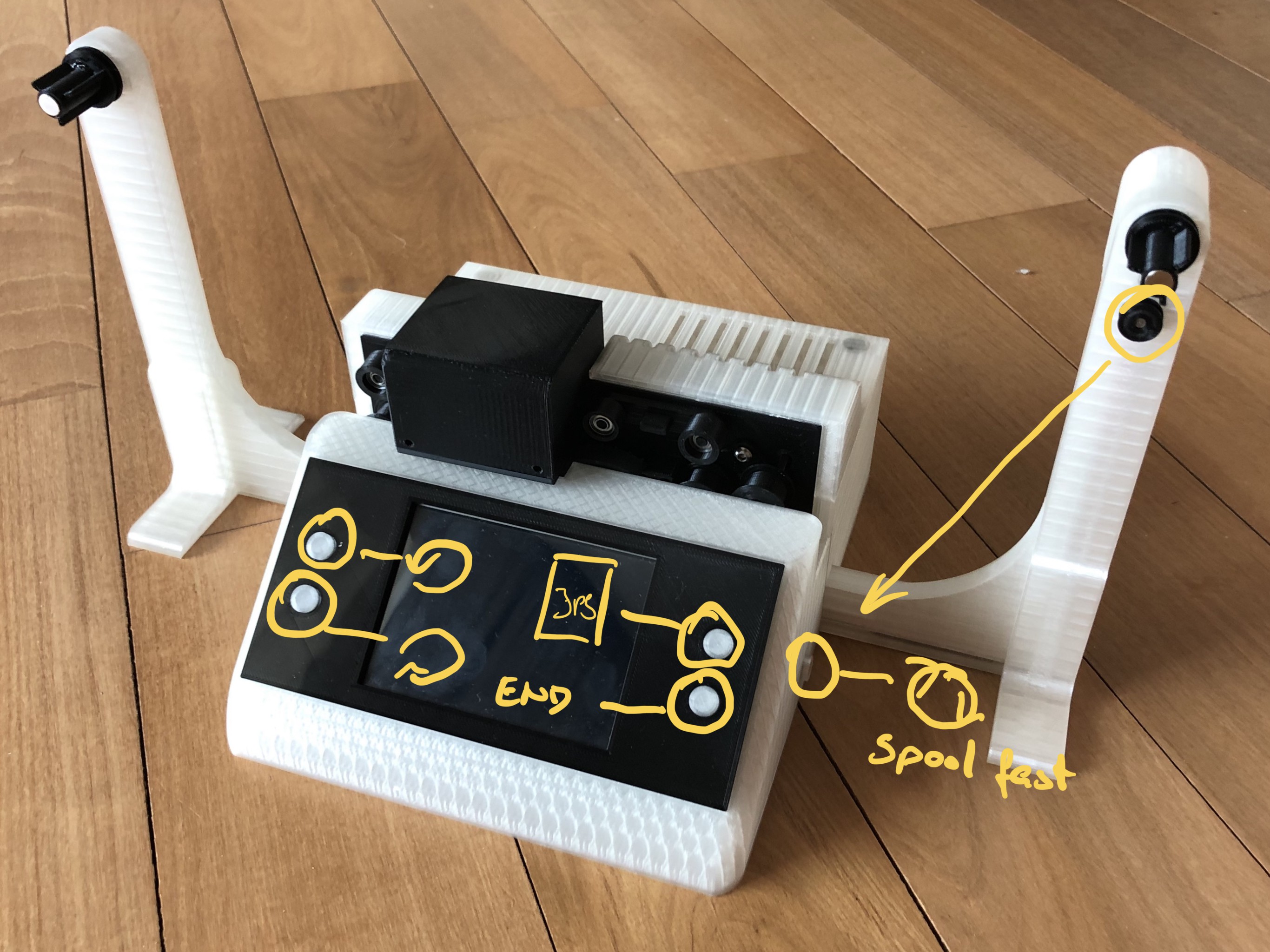
Now start testing your build:
![]()
The buttons on the left side should turn the sprocket, the ones at the right side will take a picture and safe it to the desktop (upper button) or end this test script (lower button).
While pressing the buttons (except the "end" one) the spool wheel should be turning slowly. Lift the roll that moves the interruptor wheel up and down and check if the spool wheel starts and stops. (wheel down - spool motor is on, wheel up - spool motor stops):
![]()
Also check if the LED under the camera goes on when you start the script and turns off when you stop it.
The button on the side should speed up the spool motor. Press it once - it should run now at full speed, press again and it should stop again. This button is for rewinding the film.
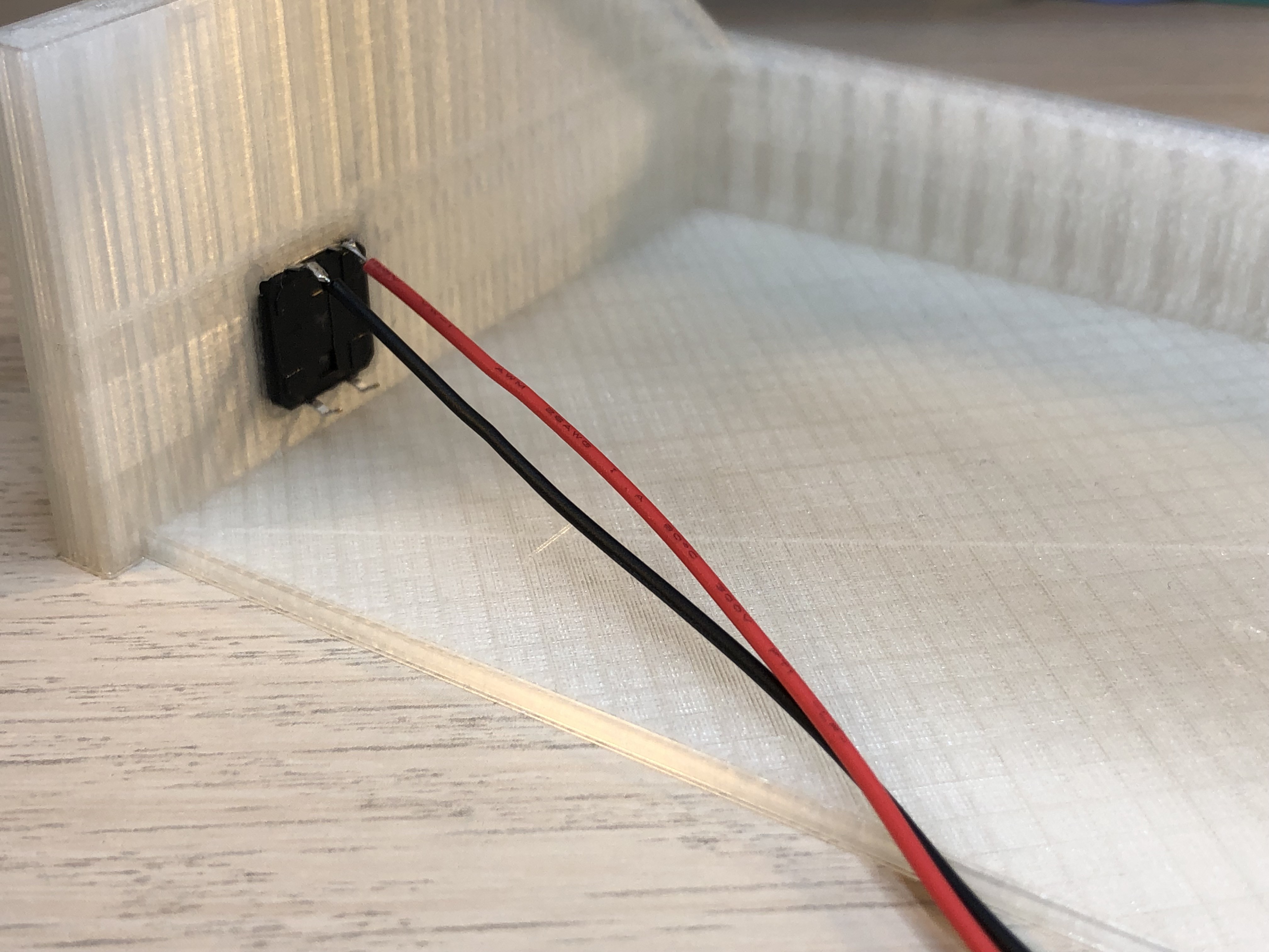
There is only one button left to be configured and tested: The on/off button next to the power plug at the back of the scanner:
I'm following Tyler's tutorial:
https://howchoo.com/g/mwnlytk3zmm/how-to-add-a-power-button-to-your-raspberry-p
Since the button is already connected, the only thing left to do is:
Open the terminal and enter:
$ git clone https://github.com/Howchoo/pi-power-button.git
$ ./pi-power-button/script/install
Thats it - when you press the on / off button now, the Raspi will shut down. You can press it again to start it up again.
Our little machine should be working fine by now.
Whats left to do is to adjust the camera, configure the display and install additional software (e.g. openCV, numpy, ffmpeg..) to enable the film scanning.
-
7Finalize Soft- and Hardware, Adjust, Scan
Adrian Rosebrock posted a very comprehensive tutorial on how to install OpenCV on Raspbian Buster: install openCV
If you follow his installation guide, you'll have everything you need to run the scanner. He offers a "faster" and a "complete" install. For our case the "fast" one is more than sufficient, but if you want to experiment more with OpenCV you may want to go with the longer one.
There are only a few things left to do on the hardware side:
Connect the spool wheel and the motor wheel with a 15mm (approximately) rubber-band. As you see, I'm using 2 pieces to ensure a tight fit.
![]()
Depending on the spool you are using, regular or super 8, you can put the spool directly on the spool wheel or you put first one of the spool wheel adapters on:
![]()
![]()
Now you can put the spools on the spool wheels and fix them with the spool fixation. If you do that for the first time, glue in the magnets to hold the wheels in place:
![]()
Now put in the film and adjust the film plate that the film goes in a straight line from the film plate to the sprocket:
![]()
Now close the camera and start the test script we have been using before.
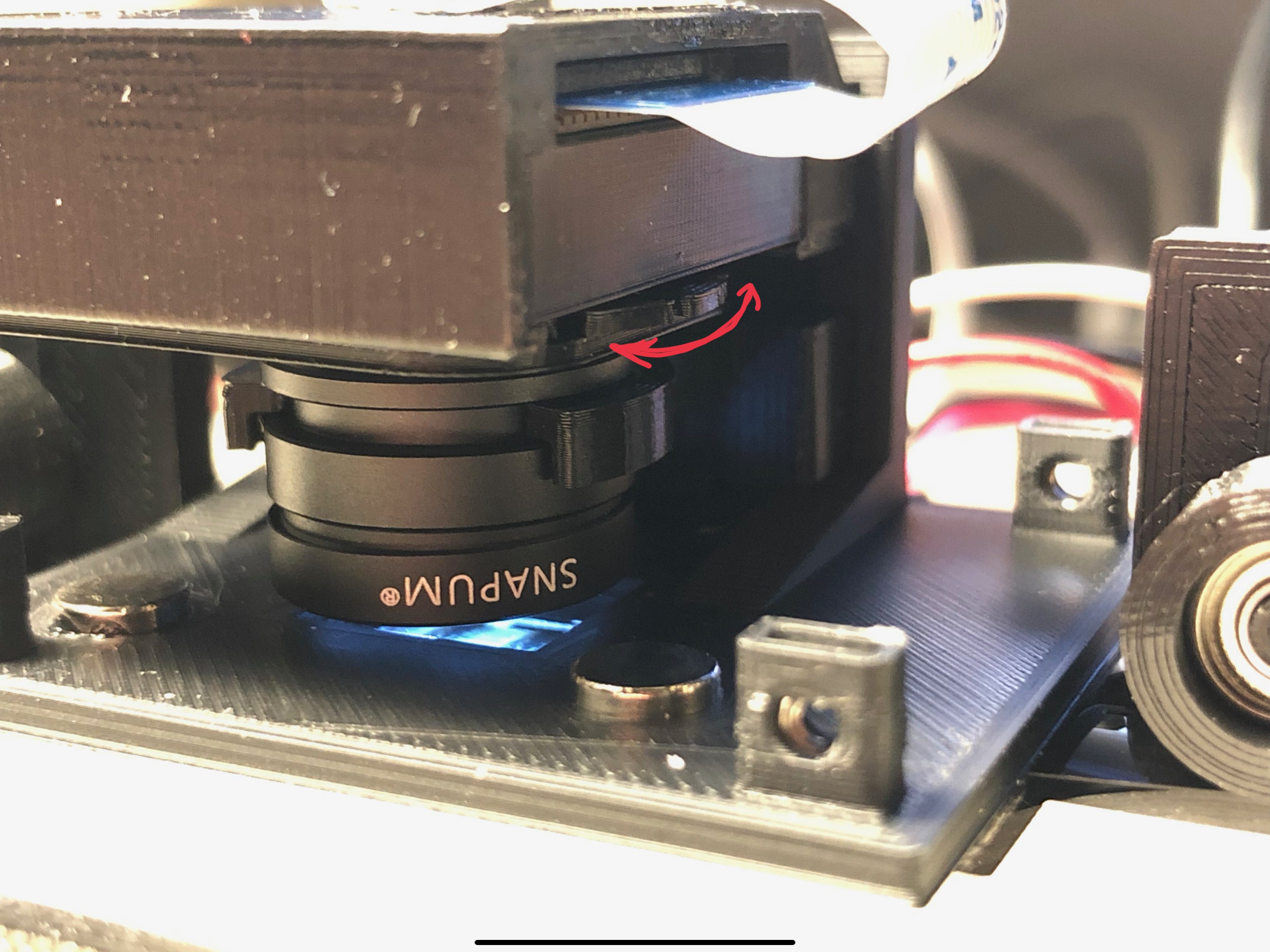
Transport the film by pushing the "forward" button (upper button left side) until you have a picture that you can use to adjust the camera's focus.
In order to do that, turn the lens adjustment tool until you have a clear picture:
![]()
Once that is done, you can put the camera cover over the camera and lens, and fix it with 3 M2 screws.
You are now ready to scan.
-
8Usage of the software - to be continued ....


Discussions
Become a Hackaday.io Member
Create an account to leave a comment. Already have an account? Log In.
It would be good to have the use of the software because it is not easy to work with OpenCv.
Thank you again for this great project and the time spent..
Are you sure? yes | no
wanderfull. Thanks
Are you sure? yes | no
3Printing is done, i'm now working on electronics !! I'm working on a standard hat.
Thank for this great project ! Can't wait to see the end of the instructions :)
Are you sure? yes | no