Close
0%
0%

OtBC

"Old-timer Board Computer"
Mostly because cheap electronics are widely available.

Similar projects worth following
On my journey to restore a Renault 4 F6 for the 4LTrophy rallye, I decided to shove some microcontrollers under the hood to enhance the driving and user experience.
I didn't design the OtBC to work with any old-timer, as it is specifically designed to work with a R4 (because of the sensors and features I personally want to add), although the codes and schematics should not be too hard to adapt to any car brand and model if you know what you're doing ;)

Build logs :

  1. Introduction
  2. Function Diagrams
  3. Miscellaneous bits
  4. GPC01
  5. GPC02
  6. GPC03
  7. I've changed my mind...
  8. ... And I've built an app.

Progress :

  • General Purpose Computers :
    • GPC01 Dev progress : Almost done, need to improve RPM reading and implement CAN bus.
    • GPC02 Dev Progress : Back to the drawing board
    • GPC03 Dev Progress : Not started, questioning it's usefulness
  • Other Modules : 
    • Electric Power Distribution : Planning started, waiting for the components to arrive by mail.
    • Improved Ignition coil : Build done, need more testing and build log.

Status :

Paused due to finals; will resume shortly.

  • ... And I've built an app.

    Frédéric Druppel12/24/2019 at 13:06 0 comments

    In the previous project log, I said that GPC02 will have Bluetooth LE. The whole point of doing this is to display the sensor data wirelessly on a readable screen, and to add toggle switches that won't be implemented in the overhead switches.

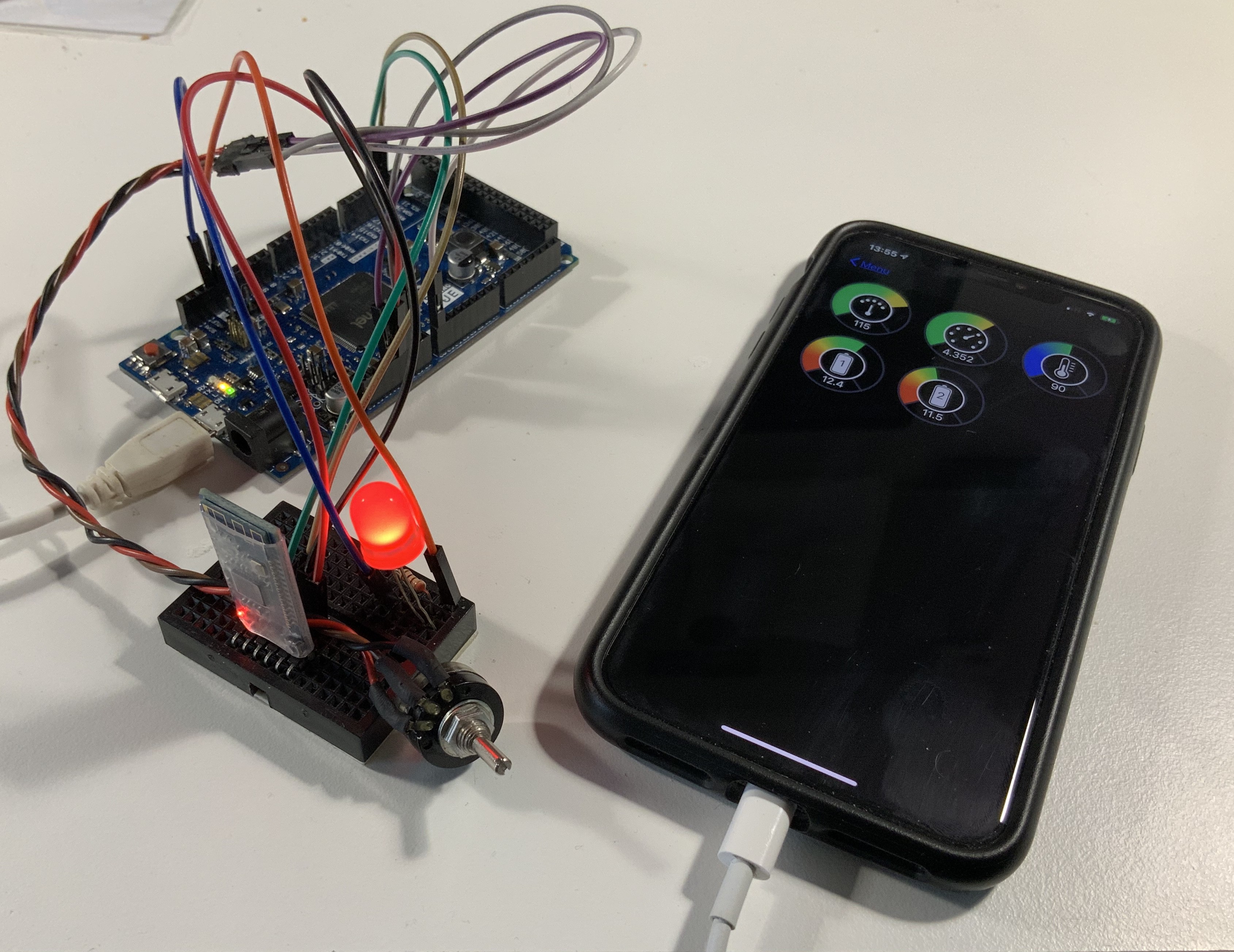
    Here's a picture of the app at the current state of the development process :

    As you can see on the right side, there are 5 gauges that display speed (KMH), engine RPM, water temperature (°C), battery 1 voltage and battery 2 voltage respectively. Of course those aren't all the available data from GPC02, but this was just a proof of concept (and also a first try on developing an iOS app with SwiftUI). Other available data will include : battery (1&2) and generator current, fuel level (although I still need to test that), sunlight UV radiation, etc.

    On the left side, the big LED is controlled via a toggle switch in another submenu in the app, and the potentiometer controls the RPM gauge. All the other gauges display a fixed value, sent bu the Arduino Due. 

    The BLE module I4m using is an AT-09, with a CC2541 IC; and with the numerous Swift, SwiftUI and iOS CoreBluetooth tutorials available online, it was relatively easy to make this app in a few days (as a complete newbie).

    All the source code will be available on GitHub at the end of the project.

  • I've changed my mind...

    Frédéric Druppel12/24/2019 at 12:45 1 comment

    In the function diagram project log, I said that GPC02 would be "used for multimedia and environmental awareness", so it would control the multimedia functions (FM Radio, Bluetooth, on screen compass,...) of the board computer system. But while I was working on the graphic screen interface, I noticed that the 128x64 had a small pixel density, and thus would be hard to read fast.. so I started to make an interface with large (touchscreen) buttons as you can see on this first radio test

    But I wasn't satisfied, and it would take a long time to implement all the menus, submenus, and functionalities I wanted to have; Basically I was rebuilding a complete aftermarket car radio system from scratch, with a few custom features.

    Consequently, instead of rebuilding one, I bought a car radio system ! Plus it even has CarPlay, so it's even better than what I wanted to make myself.

    So what about GPC02 ? Well, It will still exist, but more as a "black box" that monitors and controls features in background. It will now have a toggle switch interface (like the overhead switches in the STS programs) instead of a touchscreen interface.

    It will still have all the sensors & modules I intended to add (GNSS, Temperature, GSM,...), and also have a SD datalogging feature.

    I'm also adding Bluetooth LE, more on that in another log...

    I'm also changing the RS485 interface for a CAN bus, as the message collisions are easier to avoid.

  • GPC03

    Frédéric Druppel09/12/2019 at 22:34 0 comments

    [coming soon]

  • GPC02

    Frédéric Druppel09/12/2019 at 22:34 0 comments

    [coming soon]

  • GPC01

    Frédéric Druppel09/12/2019 at 22:33 0 comments

    This is the board computer that controls all the lights, and monitors the different engine fault sensors. Now you may wonder why I’m going through an Arduino just to control lights with a simple switch, and there is no real reason why I’m doing so, other than custom functionalities ! For example, I can precisely control the blink rate of the turn lights (which you should definitely use when turning BTW), or I can put a « Master test switch » to turn all of the lights on for visual inspection.

    But, of course, it has to be very reliable; I don’t think it would be pleasant is my headlights turn off randomly at night while I’m driving because I forgot to break a loop... So there’s a lot of thorough testing going on ! 

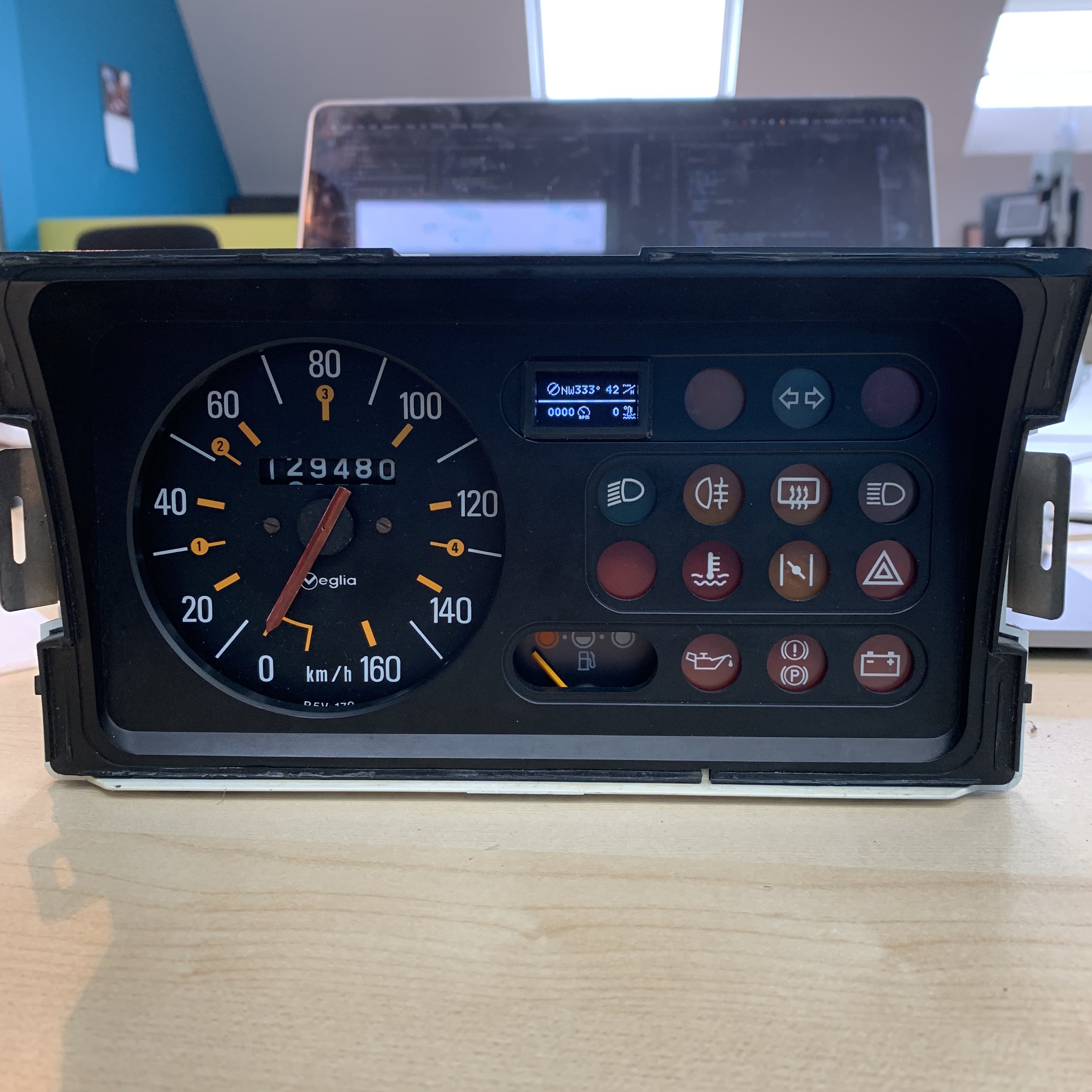
    You may have noticed a small 128x64 OLED screen embedded; This screen, when everything is OK (e.g. when there’s no fault sensor triggered), displays useful information like engine RPM, cooling fluid temperature, and GPS Speed&Heading from GPC02.

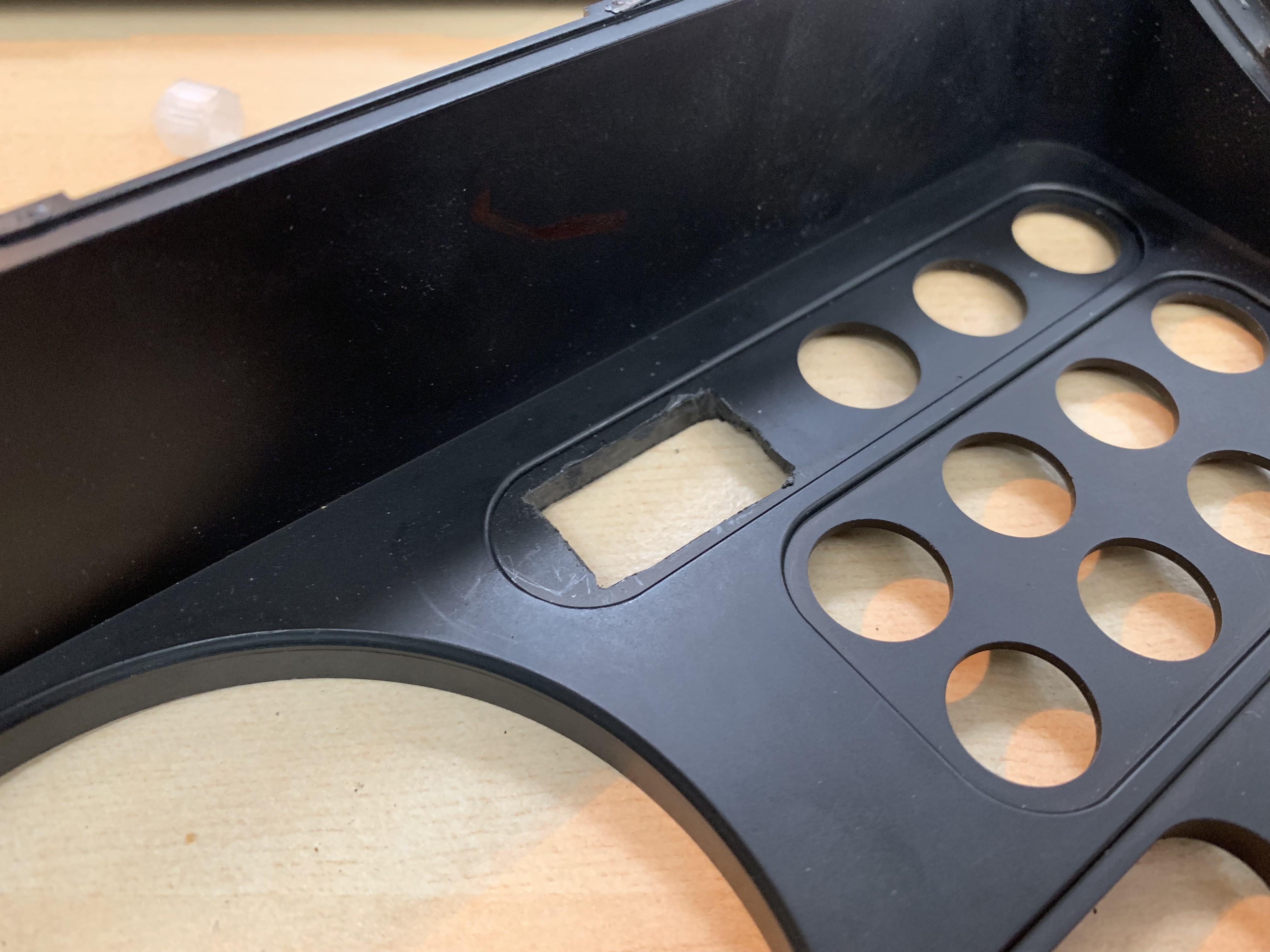
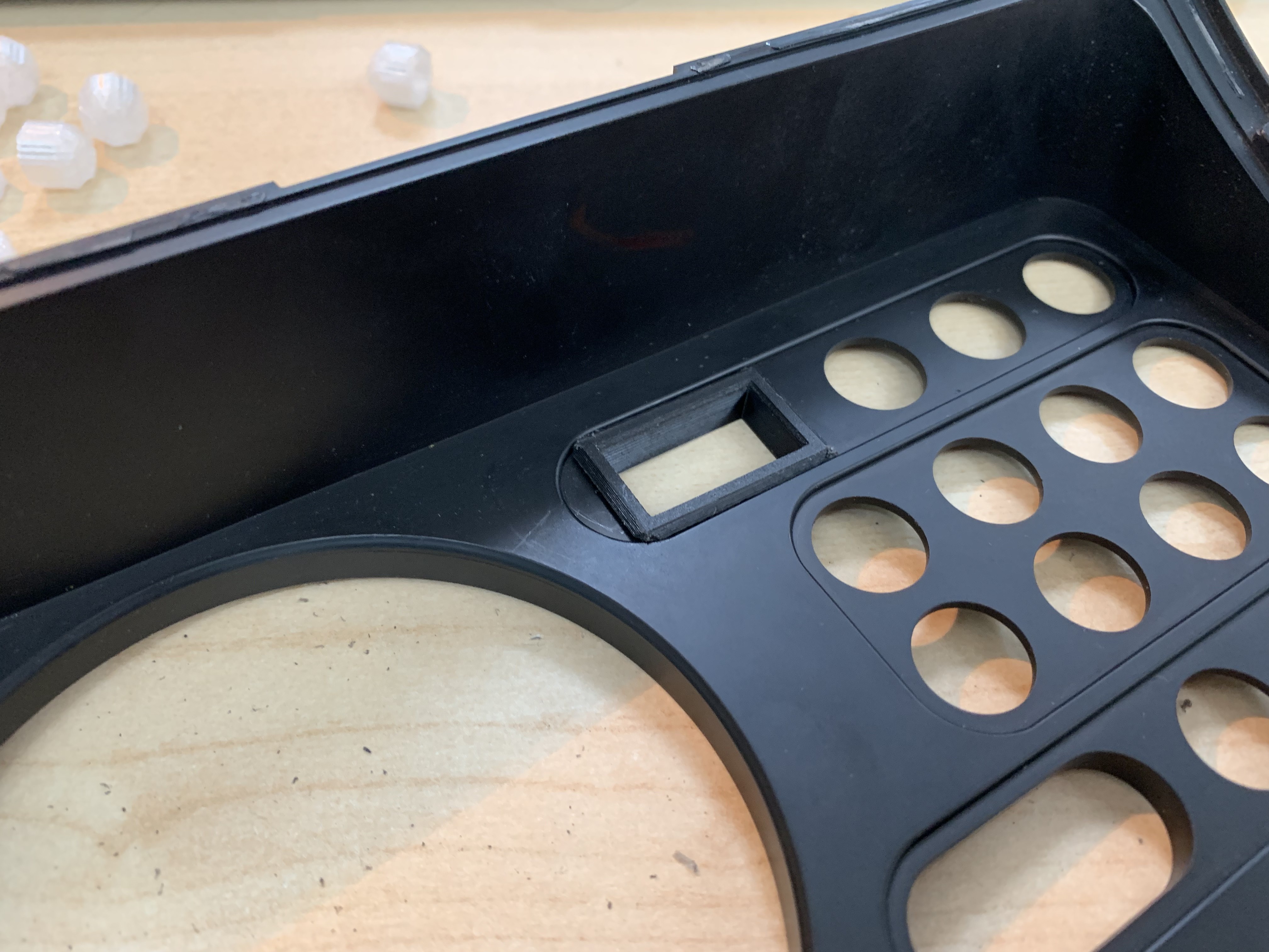
    I made a hole in the original dashboard, and printed a little fame to make it look nicer :

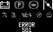
    This display also gives detailed error messages when a sensor is triggered. Here are the different logos I made for it :

    Those where drawn in Adobe Photoshop pixel by pixel, and converted to c++ arrays with LCDAssistant.exe, so I didn’t have to convert by hand all 8192 pixels of some logos.

    As you can see, there are 128x64 (shrunken down to 64x32 above), 32x32, 16x32, 16x16, and even 16x8/8x16 logos.

    The only 128x64 logo is for the "ERROR 501" screen; this one shouldn't ever show up, unless I did something wrong in my display routine and the display I'm trying to, well, display, doesn't exist.

    The 32x32 logos are on the upper row : battery, handbrake, low brake fluid and choke. 

    The 16x32 and 16x16 logos are on the second row : km/h (speed), cooling circuit temp, low oil pressure (16x32), compass (heading) and engine RPM.

    Now the 8x16 and 16x8 logos; those are actually the "P" and "Genie lamp" logo inside the bigger 32x32 brake logo. In order to save on code space, when the Arduino has to draw the "handbrake" or "low brake fluid" logo, it first draws the background (e.g. the circle with two parenthesises (32x32)), then in the middle of that the "P" or "Genie lamp", whichever is needed. This means that I only need to store one 32x32 logo array, and two smaller 16x8/8x16 logo arrays (every saved byte counts !).

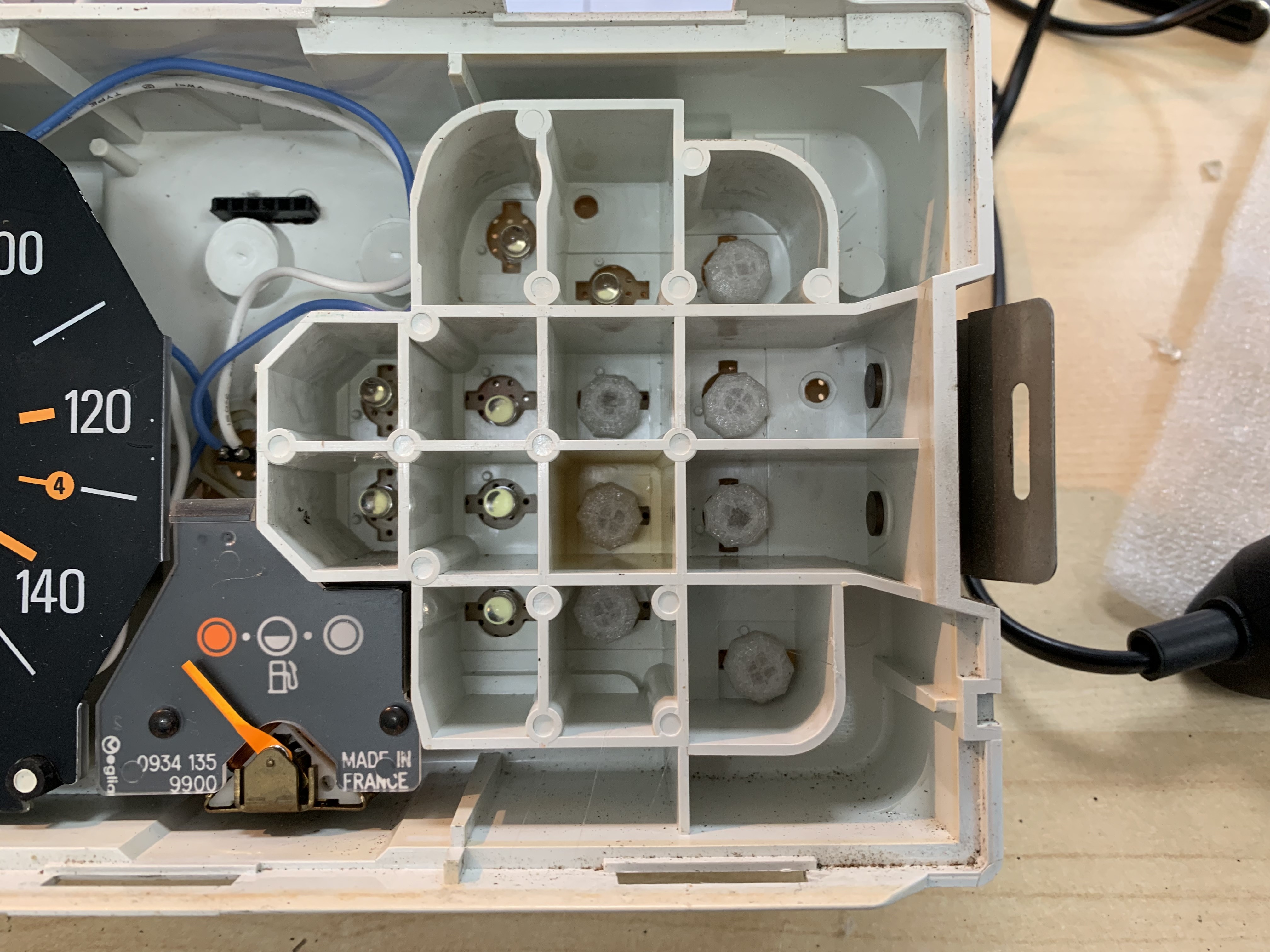
    All the original light bulbs where replaced with white LEDs with 3D Printed PETG diffusers. Each LEDs is controlled by an individual pin on the Arduino Due. You may also notice a white and a blue cable, right above a 6pin connector; the two wires are for the speed gauge backlight, and the 6p connector is for the OLED screen and the piezo speaker. The piezo was put right there so I can actually hear it above all the engine noise.

    [Remaining info coming soon]

  • Miscellaneous bits

    Frédéric Druppel09/12/2019 at 22:10 0 comments

    • I removed all the original wiring harnesses, and just put back the necessary wires to start and run the engine. Here I'm also testing a prototype of a ZVS Flyback ignition coil system (log coming soon) : YouTube link

    • First startup sequence test of GPC01 :  Instagram link

  • Function Diagrams

    Frédéric Druppel09/12/2019 at 21:29 0 comments

    Just to clarify, the board computer here does not control the engine, steering or brakes (not even the brake lights), as I do not have the skills to certify my own work to automotive standards, plus some aspects of such modifications would be illegal in my zone of jurisdiction.

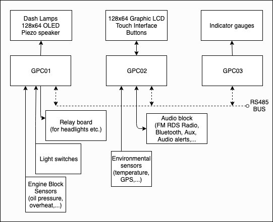
    That said, here is the block diagram of the elements of the OtBC :

    As you can see, there are three GPCs that communicate with each other via a RS485 bus. GPC01 and 02 are based on an Arduino Due, and GPC03 on an Arduino Uno or Mega (I'm not sure yet as dev has not begun on this one).

     I'm splitting the board computer in three parts for safety and coding convenience : every GPC can work on their own, but they can share values (like engine RPM from GPC01, GPS speed from GPC02, etc.), plus I can probe the RS485 bus with a computer with an Ad Hoc interface.

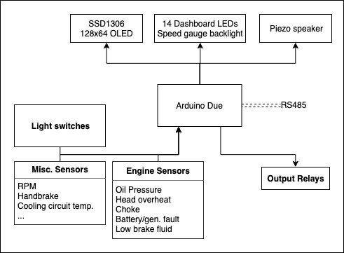
    GPC01 is used for the vital functions : lights, dash lamps and warnings. Its code has to be lightweight and reliable. I'm not adding too many bells and whistles to it, and I'm intensively testing it as a crash would inevitably disable all the lighting of the car, which is not a good thing while driving.

    The code works by multithreading the Arduino Due with the Scheduler library. I've already used this lib, and when used carefully it is really reliable.

    There are threads that read the switches states ans sets flags if on, and other threads that read the flags and sets the outputs high or low. Why go through flags ? Well, it's easier to debug, to force a state, and to manipulate in other parts of the code; for example, I do not have to call the "digitalRead()" function (which can slow down the code considerably) every time I want to know the state of something. TL;DR: Reading a boolean is faster than calling a "digitalRead()" function every time.

    [GPC02 schematic block image placeholder]

    GPC02 is used for multimedia and environmental awareness (fancy words for "It knows the temperature and GPS data" amongst other things). The multimedia aspect of this GPC consists of an Audio block with an fm radio module and a bluetooth receiver etc., and a rudimental navigation system (= on screen compass). It also has an audio module which reads MP3 files from an SD card; this is used to playback recording alert messages, when a problem appears (for example, a voice will say "Warning, engine overheating", when the engine overheating sensor triggers). [this section will get more detailed as the dev of GPC02 continues].

    [GPC03 schematic block image placeholder]

    GPC03 doesn't really control anything, it's more of a RS485 sniffer that displays the data on rotary indicator gauges. As the dev of GPC03 has not yet begun, I don't really have to say anything yet, so this section will change when the dev has begun.

  • Introduction

    Frédéric Druppel09/12/2019 at 20:23 0 comments

    The whole reason I'm doing this is because I want to participate to the 4LTrophy (wiki), in which each crew has to bring school supplies on board of a Renault 4 from Biarritz France to schools in Fez Morocco (and other schools along the road).

    Thus, each crew has to have a Renault 4 :

    Image credits

    The variant of 4L I have is the 4L F6, which is the longer van model. It has a 1108cm³ 4-cylinder gasoline engine (with a power output of 47hp), and a manual 4+1 speeds transmission box with a Front Mid-engine, Front-wheel-drive layout. It has no power steering or power brakes, but it doesn't need to as the whole car only weighs 750 kg (1,653 lb).

    I'm not going to cover the chassis restauration on mine in detail here, as the project is dedicated to the board computer I'm building for it (I may probably still make one project log dedicated to only that though).

View all 8 project logs

Enjoy this project?

Share

Discussions

Similar Projects

Does this project spark your interest?

Become a member to follow this project and never miss any updates