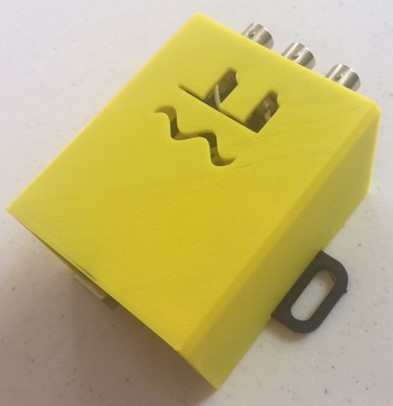
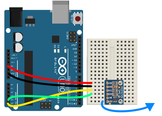
SignalBuddy is an easy-to-make, easy-to-use signal generator for scientific applications. Making friends is hard, but making SignalBuddy is easy. All you need is an Arduino Uno! SignalBuddy replaces more complicated and (much) more expensive signal generators in laboratory settings where one millisecond resolution is sufficient.This page describes how to make the 3D printed enclosure and wire everything up. A full description of the code can be found at the SignalBuddy github repo: https://github.com/rwarren2163/signalbuddy
3D print the base and lid of the enclosure using the .stl files from the SignalBuddy github repo. The unit of the parts is inches.
2
mount Arduino
The Arduino can snap into the base as shown here.
Now snap the prototyping shield (like this one, or similar) into the Arduino, and insert the MCP4725 into the breadboard.
3
add BNC jacks and wire everything up!
Mount the BNC jacks into the side panel. Solder wires connecting the ground terminals of the BNC jacks to each other, and another connecting them to the ground on the shield. The gold pin on the 3 BNC jacks should be connected to Pin 2 (this is the external trigger input), VOUT of the MCP4725 (this is the analog output), and Pin 11 (this is the digital / PWM output).
On the MCP4725, connect GND to ground, VDD to 5V, SCL to A5 on the shield, and SDA to A4 on the shield, like this:
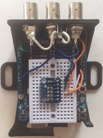
I implemented Signal Buddy accordingly, and found it works greatly. For the more practical use, it could have processed longer trains of pulses. Length of signal seems to be limited by integer type.