land-boards.com
-
SD Card Library Examples
10/23/2019 at 14:23 • 0 commentsThere is a PSoC library (emFile) for SD cards but it's more oriented towards supporting FATxx (DOS) file systems. Grant's code already takes care of the CP/M file system details so those examples would be painful to adapt. The Arduino library, also, centers around DOS.
The lower level connection is the SPI and that's easy for the PSoC since it has SPI interfaces built in. PSoC Creator makes the API code to talk to the SPI.
We've already done the Z80 to SD card interface. It's a series of I/O space addresses which set the block number, write a command, read the status and read/write data from/to the SD card.
Next, we need to fill in the functions to map Grant's calls into PSoC functions to map between the Z80 I/O and SPI interfaces (Grant''s details are here).
Links
The following series of BLOG posts is really good and actually gives the C code for a Microcontroller. The author helps quite a bit by working the examples in detail. If you really want to understand SD card access it's a great place to read.
Best part is he provides his source code. I can't use the code, as-is, since he's made some trade-offs I don't need and my hardware has different API calls to his ATMega SPI interface but it gets me close.
One of the trade-offs is that he's written the code to read from the SD card in small chunks to support Microcontrollers with very little SRAM. That's not necessary in this case since we've got a PSoC with 32KB of SRAM. Having 2 dedicated buffers of 512-bytes each barely makes a dent in our internal SRAM. I think the right approach is to read an entire block into the SRAM of the PSoC and have the PSoC feed the data out to the Z80.
Here's the helpful series:
- Simple FAT and SD Tutorial - Part 1 looks at the boot record of the SD card
- Part 2 - FAT oriented but still helpful background
- Part 3 - The physical part
- Part 4
SD_init code from Part 4
Here is the code from part 4 of the series above. The comments show what the command would be if typed into a Bus Pirate.
unsigned long sd_sector;
unsigned short sd_pos;

char SD_init() {
    char i;

    // ]r:10
    CS_DISABLE();
    for(i=0; i<10; i++) // idle for 1 bytes / 80 clocks
        SPI_write(0xFF);

    // [0x40 0x00 0x00 0x00 0x00 0x95 r:8] until we get "1"
    for(i=0; i<10 && SD_command(0x40, 0x00000000, 0x95, 8) != 1; i++)
        _delay_ms(100);

    if(i == 10) // card did not respond to initialization
        return -1;

    // CMD1 until card comes out of idle,
    // but maximum of 10 times
    for(i=0; i<10 && SD_command(0x41, 0x00000000, 0xFF, 8) != 0; i++)
        _delay_ms(100);

    if(i == 10) // card did not come out of idle
        return -2;

    // SET_BLOCKLEN to 512
    SD_command(0x50, 0x00000200, 0xFF, 8);

    sd_sector = sd_pos = 0;

    return 0;
}
Makes Sense of a Past Mystery
The initialization part of this makes sense of something I saw when I wrote another SD card driver before (for my 32-bit RISC design in an FPGA). I don't think it did the initialization right and when it ran it would sometimes not work for the first SD card access. Later accesses worked just fine. I think it might have been lacking the initialization sequence.
In a later log I will take this example code and adapt it to the PSoC.
-
SD Card Physical Connections
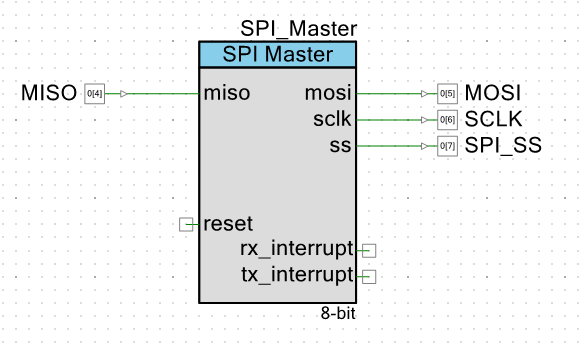
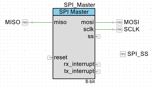
10/23/2019 at 09:19 • 0 commentsCreated a SPI_Master in the PSoC TopDesign.cysch file:
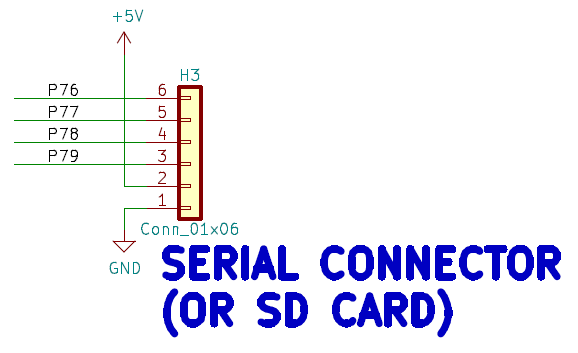
PCB Schematic
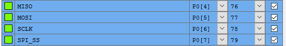
PSoC pin list
Signal Name PSoC Pin H3 pin MISO 76 H3-6 MOSI 77 H3-5 SCK 78 H3-4 SS 79 H3-3 Power +5V H3-2 Ground GND H3-1 SD Card Adapter
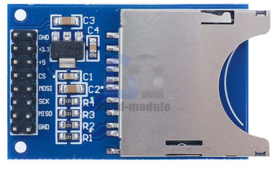
These adapters are dirt cheap on Ebay. The extra row of pins allows debugging to be done easier.
The Z80 runs at 5V and SD Cards run at 3.3V. The adapter card has a voltage regulator to make 3.3V from the 5V. They don't typically have level shifters for the digital lines but they have 10K resistor in series with the 4 control lines so that should be OK.
Cable to connect adapter to Z80_PSoC connector.
Modified the schematic to make SS an output pin. That's because It needs to be held high for at least 74 clocks during initialization. Could be better to use a mux so that after initialization it could be switched to the in-built SPI interface.
-
SD Cards and CP/M
10/22/2019 at 16:29 • 0 commentsI'm not totally sure which source code is running on my card. That's because I grabbed the file out of my FPGA design sources and there's no matching source file name. Funny that I can run code that I don't know what the source is but it wasn't all that hard to run. I ran it until the I/O access hung and I could see that the Z80 was accessing a 2nd ACIA. My PSoC code didn't have a 2nd ACIA and the source code had no access code for a 2nd ACIA. So I know the .asm file I was using didn't match the .HEX file.
Digging deeper into Grant's page I found what I think may be the the original source code - basMon.asm. It also has listing file BASMON.LST. The code looks right. It's 8KB long, it needs two ACIAs.
It should be pretty easy to examine the program that is downloaded by using the Front Panel and see if it matches BASMON.LST.
The PSOC Creator menu options Tool "Debug without programming" lets me restart the code. The compile options are set to include the Front Panel support. After testing the SRAM, the front panel displays the contents of address 0x0 which are 0xF3 which is a DI instruction. Not a surprise since probably all Z80 code starts this way.
Let's see if the Monitor is present in this code. After all the MON in BASMON would imply that it is present. The monitor code starts at address offset 0x00EC.
0294   00EC             ;------------------------------------------------------------------------------
0295   00EC             ; Monitor command loop
0296   00EC             ;------------------------------------------------------------------------------
0297   00EC 21 EC 00    MAIN          LD   HL,MAIN    ; Save entry point for Monitor
0298   00EF E5                  PUSH HL        ; This is the return address
0299   00F0 CD 22 01    MAIN0        CALL TXCRLF    ; Entry point for Monitor, Normal
0300   00F3 3E 3E               LD   A,'>'    ; Get a ">"
0301   00F5 CF                  RST 08H        ; print it
Setting 0xEC on the second row up and pressing the LDADR switch displays the contents of the address which is 0x21. That matches the source code so I think I'm on the right track. The function I am most interested in is CPMLOAD. It looks like this:
0505   01F1             ;------------------------------------------------------------------------------
0506   01F1             ; CP/M load command
0507   01F1             ;------------------------------------------------------------------------------
0508   01F1             CPMLOAD
0509   01F1
0510   01F1 21 03 02            LD HL,CPMTXT
0511   01F4 CD 1B 01            CALL M_PRINT
0512   01F7 CD 29 01            CALL M_GETCHR
0513   01FA C8                  RET Z    ; Cancel if CTRL-C
0514   01FB E6 5F               AND  $5F ; uppercase
0515   01FD FE 59               CP 'Y'
Checking address 0x1F1 and following address confirms this is very likely the correct listing for the code that is running on the card. Odd since Grant's documentation doesn't mention BASMON.asm at all. I think BASMON is a combination of BASIC.ASM and MONITOR.ASM which Grant does mention. It looks to me like he put the output of that file in with the FPGA VHD files since the .HEX output file is what the FPGA compiler loads.
This gives us a shot at figuring out what is wrong when this has problems - and it will have problems since there's a fair amount of heavy lifting to do getting the SPI to work with an external SD card and CP/M. Given this, we should also be able to correlate the FPGA design used for the SD card interface with Grant's software.
SD Controller in the FPGAI've got some recent experience with the SD controller that Grant uses in the FPGA. I designed a 32-bit RISC CPU (R32V2020) and got the controller working with my code. The organization of the control registers on that design was:
; SD Card base address is 0x1000
; Register Addresses
;    0x1000    SDDATA        read/write data
;    0x1001    SDSTATUS      read
;    0x1001    SDCONTROL     write
;    0x1002    SDLBA0        write-only
;    0x1003    SDLBA1        write-only
;    0x1004    SDLBA2        write-only (only bits 6:0 are valid)
Here's some more of the details from that project.
; To read a 512-byte block from the SDHC card:
; Wait until SDSTATUS=0x80 (ensures previous cmd has completed)
; Write SDLBA0, SDLBA1 SDLBA2 to select block index to read from
; Write 0 to SDCONTROL to issue read command
; Loop 512 times:
;     Wait until SDSTATUS=0xE0 (read byte ready, block busy)
;     Read byte from SDDATA
Grant must be doing something similar for this code. Grant's code starts with the label readhst:. and reads the SD_STATUS and SD_DATA locations. It calls setLBAaddr which does three writes to the addresses SD_LBA2..SD_LBA0. These are defined along with the other Z80 I/O addresses as:
0060   0000             SD_DATA        .EQU    088H
0061   0000             SD_CONTROL    .EQU    089H
0062   0000             SD_STATUS    .EQU    089H
0063   0000             SD_LBA0        .EQU    08AH
0064   0000             SD_LBA1        .EQU    08BH
0065   0000             SD_LBA2        .EQU    08CH
There are six separate Z80 I/O address registers for these values.
- SD_DATA is the input/output buffer
- SD_CONTROL is a write address for the control of the SD card
- SD_STATUS is the same address which tells the status of the interface.
- The next three SD_LBAx are the block addresses.
This seems straightforward enough.
SD vs SDHC Cards
The code above doesn't deal with LBA3 which it would need to if SDHC cards are used. We'll take note of that and figure out if we can do something about that in the future. If I recall correctly the card type can be interrogated and the right code inserted for the right type of card. It might be as simple as just using the lower area of a really big card and setting LBA3 to be 0x00 always.
The code does partly anticipate SDHC cards in the memory storage since it reserves a spot for lba3. Grant initializes the lba3 value to 0x0 (in CPMLOAD2) but the code to talk to the SD card (setLBAaddr) doesn't use it as Grant notes in a comment.
Here's the LBA storage space in Grant's code.
0073   3004 00          lba0        .DB    00h
0074   3005 00          lba1        .DB    00h
0075   3006 00          lba2        .DB    00h
0076   3007 00          lba3        .DB    00h
For the moment we'll just use an SD card that is 2 GB and already has CP/M loaded onto it. This is not quite cheating since Grant details how to make the card and we did that for the Multicomp FPGA build. Ultimately, it would be preferable to use an SDHC card since it's getting increasingly harder to find low capacity SD cards.
The PSoC SD Card Driver
We have enough information now to start to design the PSoC low level software for the SD card interface between the Z80 and the PSoC. We need six IO space addresses. Three of them are write-only from the Z80 (lba0..2). I'm considering the Compact Flash (CF) start earlier to be a dead end since we now have code that runs and should be able to boot CP/M. This way we won't have to make the CF card code to SD card code.
The PSoC definitions for the SD card are:
    #define USING_SDCARD
    #ifdef USING_SDCARD
        #define SD_DATA                 0x88
        #define SD_CONTROL            0x89
        #define SD_STATUS            0x89
        #define SD_LBA0                0x8A
        #define SD_LBA1                0x8B
        #define SD_LBA2                0x8C
    #endif
I changed all references to CF into SD and set up the appropriate functions. Here's the function names:
void    SDReadData(void);
void    SDWriteData(void);
void    SDReadStatus(void);
void    SDWriteCommand(void);
void    SDWriteLBA0(void);
void    SDWriteLBA1(void);
void    SDWriteLBA2(void);
void    SdWriteLBA3(void);
The PSoC code compiled without error. This should be all that is needed for the Z80 side access to the SD Card interface. We still need to work out the PSoC to SD Card side in the next log(s).
-
Third Software Build Running
10/22/2019 at 13:27 • 0 commentsGrant Searle has a third software build that might prove handy towards having external flash card storage. This is the software that he uses with his Z80 on an inexpensive FPGA project. This is named the Multicomp project.
I got this third build working in minutes.
It only took a bit of messing around since Grant's stock software assumes two ACIA (M6850 parts). I copied the M6580 code that I made for the previous logs and deleted most of the guts of the lower level routines. The read status routine returns saying that there are no characters in the second ACIA. That is how Grant chooses between the two serial ports - whichever port returns the space is selected as the code default - handy solution to the problem. Without this added code Grant's software hangs on the access to the missing 2nd ACIA.
Why Yet Another Build of Grant's software?
This is another 56KB SRAM (in BASIC) build but with critical differences. Grant's 48K build supports an assembly language monitor and CP/M. Grant's other 56K build only supports NASCOM BASIC (no CP/M). This build supports both NASCOM BASIC and CP/M support all packed into an 8K PROM space. That's cool because it's getting 8KB more of program space for BASIC with the cost of losing the machine code monitor. Not a real big cost but I could always load the old build if I wanted to mess around with the monitor.
What I really wanted from this build is Grant's hardware/software support for CP/M that he has in the FPGA. In Grant's discrete (non-FPGA designs) he uses an external Compact Flash (CF) card which requires a bunch of connections from the CPU bus and these are expensive I/O on an FPGA. For the FPGA version, Grant uses an SD card which only needs a 4-pin SPI bus to control it. And the PSoC also has an SPI bus and 4 spare connectorized pins so it should be possible to get an SD card working with this software build. I say possible since it's yet to be done but this is where we are headed next.
Grant's Documentation for the SD Card Interface
Grant has some instructions on his page about the SD card on this page and the other support that is needed to do this (at least how he did it with his FPGA solution).
Trading Spaces
The first thing is that the memory mapper needs to swap out the EPROM for SRAM when the program writes to a particular memory location.
When CP/M starts, the ROM is to be disabled.
The CP/M images are set up so that a write to $38 will
turn off the ROM, resulting in ALL of the 64K address space
being the SRAM instead.
This is almost unneeded with this board design. The reason is there's no actual EPROM on the card - all memory is already SRAM. And CP/M uses SRAM. I say almost because Warm Boot complicates that. If CP/M overwrote the data in the first 8K then the board can't boot back into the initial prompt and run BASIC without reloading the code. That really would be no big deal but supporting page swapping shouldn't be difficult since the hardware is present already to do the swap.
Although there is hardware support in the PSoC for page mapping and swapping but it hasn't been used yet. The PSoC code does test all 512KB of SRAM when it powers up so we know the SRAM is working. What is missing is the I/O routine to deal with the swapping.
Adding the I/O handler for the swap write should be similar to the other handlers. To start with a #define for this memory mapper would look like in Hardware_Config.h:
#ifdef GRANT_FPGA_CPM // Swap out first 8KB
I named it _1 since there will likely be any number of memory mapping schemes employed with this hardware.
It is set to undefined at the top of the file and then defined within the particular build section of the file that corresponds to this build - noted by:
#ifdef GRANT_FPGA_CPMThis then gets added to this section as:
    #define USING_MEM_MAP_1
    #ifdef USING_MEM_MAP_1
        #define MEM_MAP_SWAP        0x38
    #endif
The code to deal with this gets added to Z80_IO_Handle.c as a new switch case statements. The code to perform the I/O handler needs to be written, let's put in a stub for now called write_mem_map_1.
#ifdef USING_MEM_MAP_1
        case MEM_MAP_SWAP:
            if (ioCrtlRegVal == REGULAR_WRITE_CYCLE)      // regular write cycle
            {
                write_mem_map_1();
                return;
            }
#endif
Now that we have a need for a routine it is a good time to create a .c and .h file for memory mapper routines. Let's call these Z80_Mem_Mappers.c and .h. In addition to this function, they will contain any memory mappers we might need in the future. Remember we have 512KB of SRAM and this only uses one additional page.
There are a couple of registers in the PSoC that need to be dealt with to swap pages. An earlier log entry (Z80 Memory Mapping/Bank Switching) described the design intent earlier for this project. There are some registers that need to be initially set (are possibly already set) so an initialization function would be smart to create at this point. That way we know where we are starting from.
The BankBaseAdr register sets the base address of the comparison. For this built it needs to be set to 0x00 initially and it will never change.
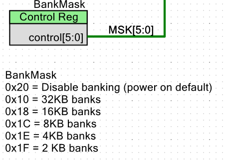
The BankMask register is set for the bank size per the table on the schematic:
We want an 8K bank so we need to set the BankMask to 0x1C. This also should not change after it is initialized.
At the end of the logic on that page this means that any access to the first 8KB of addresses will result in the BANKED signal being asserted. When BANKED is asserted it causes the upper SRAM addresses to come from the AdrHighOut register. This implies that AdrHighOut should have contents of 0x00 until the swap control word is written. So, this means that the initialization values of the registers are:
- BankBase 0x00
- BankMask 0x1C
- AdrHighOut 0x00
It almost doesn't matter what value is given for the upper address lines when BANKED is selected. To swap to another page we just need to set one of the higher bits A[18..15] to 1. For this build let's just load the AdrHighOut with 0x20 when the bank selection address is written from the Z80. The intialization code looks like:
void init_mem_map_1(void)
{
    BankBaseAdr_Write(0x00);
    BankMask_Write(0x1c);
    AdrHighOut_Write(0x00);
}
The function to perform the memory map swap looks like
void write_mem_map_1(void)
{
    AdrHighOut_Write(0x20);     // Set A18..A16 to 0x1
    ackIO();
}
This code compiles without error.
Testing the Bank Swapping
When Grant's code loads CP/M it does fetches from the SD card and loads the code into the CP/M address space at 0xD000. He describes this in the address map as:
Once CP/M is loaded

0000-FFFF RAM

0100 Transient program area (applications)
D000 CP/M System
E600 BIOS
This will be challenging to test since it will require the SD card code to work in order to verify it works. Grant includes some source code but is lacking the critical code for this function.
There's little visibility into the mapper from the PSoC code. Remapping the LED out of the control register it is contained in and onto the BANKED line might be one way of having a visual indication that the bank memory is being accessed.
Another way to test this might be to write a piece of code to see if it works. The test code would need to run in higher memory and do read/writes of the lower memory. That's possible but sounds like more work than I want.
In the next log we'll take a look at Grant's code for loading CP/M and see how it work with the SD card.
-
Compact Flash Emulation?
10/20/2019 at 19:42 • 0 commentsI'd like to get something very difficult going next. Maybe Grant's Compact Flash code? I'd like to get it working with Grant's stock 9-Chip Z80 code. I'd really like to map it to an SDHC card instead of the more ancient Compact Flash. An SDHC card only needs a SPI bus connection for the physical connection.
Physical Connections in Grant's Design
Grant has the following connections in his 9-Chip Z80 design to connect to the CF from the Z80 bus.
Grant uses I/O addresses 0x10-0x1F and connects the Z80 lines A[2..0] directly to the CF. Makes me wish I had put the Z80 lines onto a connector - I'd only need a Chip Select now and that would be easy. Grant generates a single Chip Select line when he is accessing the CF card that covers the 0x10-0x17 range. (The Front Panel address range (0x18-0x1F) is already out of the way so I have no conflicts with his code.)
Grant hooks up other Z80 lines:
- Power (5V) and Ground
- A[0..2] - already mentioned
- D[0..7]
- IORD*
- IOWR*
- CS* - Chip select - asserted for the address range 0x10-0x17
- RESET*
- BUSY_LED - Status LED (from the CF card) - Nice to have but, don't need it
CF Mode?
Grant's page describes the method of connection as:
Additionally, the CF is set up as "IDE" mode so it only requires 3 address lines
and one chip select.
This is why Compact Flash Drives can be connected to IDE connectors with purely passive connections.
This page has some hints on the IDE mode. There's more information here.
Grant has the following in his monitor.asm code:
; CF registers
CF_DATA        .EQU    $10
CF_FEATURES    .EQU    $11
CF_ERROR    .EQU    $11
CF_SECCOUNT    .EQU    $12
CF_SECTOR    .EQU    $13
CF_CYL_LOW    .EQU    $14
CF_CYL_HI    .EQU    $15
CF_HEAD        .EQU    $16
CF_STATUS    .EQU    $17
CF_COMMAND    .EQU    $17
CF_LBA0        .EQU    $13
CF_LBA1        .EQU    $14
CF_LBA2        .EQU    $15
CF_LBA3        .EQU    $16
This seems pretty straightforward. Where there are two EQUs at the same address the first one is the write value and the second is the read value. I'm going to add support for this to the 9-Chip build. I will spare the reader the details - at least for the present moment - but I want to set it up to step through the code and watch what the Z80 tries to do when booting CP/M. This will be educational - for me at least.
This will be very similar in steps to the M6850 emulation I completed in the most recent logs. If this looks promising I may pick it up here in the logs for this project.
Added: A couple of quick observations.
Grant's code in monitor.asm only does reads of particular low sectors. That's because it is loading CP/M. Once CP/M loads it must have it's own software for read/writing SD card sectors. That may complicate emulation because I may need to dump the code that is running . Fortunately Grant includes the CP/M code.
The file cbios128 looks like it's the low level IO routines and it uses the same $EQU values as Grant's monitor.asm code. So it should be easy to pick out what it does from there.
-
6850 Emulation with a PSoC (Part 4)
10/20/2019 at 18:56 • 0 commentsIn the last 3 logs we created an M6850 emulator based on the SIO that we already have. At the last step the program compiled correct. Let's try and get it to work. I'm sure I made mistakes when I did the previous changes. First I'm going to check the current build into GitHub with a note that it's a WIP.
First, I've turned the Front Panel back on so that I can check the downloaded code. That is now as easy as changing the #undef to a #define for the Front Panel. Stepping through the first part of the code shows it loaded properly into the SRAM.
However, pressing RUN on the Front Panel doesn't show any output on the USB port. So much for just up and running. I am probably missing some subtle part of Grant's implementation. Just to rule out breaking something fundamental I switched back to the 9-build code and it ran fine. So it's apparently something related to the M6850 emulator.
Debugging I/O with the PSoC Debugger
Debugging is really nice with the PSoc. You can set breakpoints and run the code. The Z80 waits around for the PSoC and since it's a CMOS part there's no problem with asserting WAIT* indefinitely. Assuming the problem relates to the I/O code let's set a breakpoint at the beginning of the handler - function HandleZ80IO( ). The debugger stops at the beginning of main and has to be told to Resume Execution (F5 is the shortcut).
Since I have the Front Panel code still emulated I have time to restart PuTTY before hitting the RUN button on the Front Panel. This probably isn't strictly required since the PSoC waits for the USB to come up before it does I/O anyway.
F11 single steps through the PSoC code. The first transfer has ioCrtlRegVal with the value 0x1A. As you might expect that's a REGULAR_WRITE_CYCLE. The register ioZ80Addr shows that the Z80 is writing to address 0x80. Grant's INIT code shows this access first.
INIT:
               LD        HL,TEMPSTACK    ; Temp stack
               LD        SP,HL           ; Set up a temporary stack
               LD        HL,serBuf
               LD        (serInPtr),HL
               LD        (serRdPtr),HL
               XOR       A               ;0 to accumulator
               LD        (serBufUsed),A
               LD        A,RTS_LOW
               OUT       ($80),A         ; Initialise ACIA
Earlier we saw
RTS_LOW .EQU 096H
Stepping through the code shows it calling M6850WriteCtrl( ) as it should and the variable M6850_Ctrl is being set to 0x96 (as it also should). We can also see a TBD we left there which says there may be more to do when the control register is written. After stepping through this code i hit F5 to run until the next I/O request.
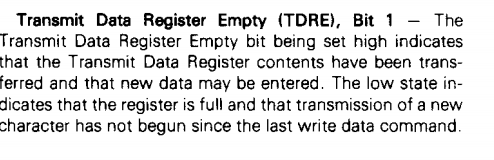
The next I/O transfer has ioCrtlRegVal with the value 0x1C which is a REGULAR_READ_CYCLE of the same location which should be a read of the status register. This could be where the problem is since that is uninitialized at startup unless there's code added to set the initial values. The SIO code didn't need any initialization of the values. The value is 0x00 and may or may not be initialized by the CPU. That would indicate that there is no receiver character but it also indicates that the transmitter is busy sending a character and it will never get set to anything else.
My guess is that Grant's software will spin on reading this until it gets set to indicate it is empty. Let's add code to initialize the M6850 status register before the code runs. We are missing any handler at all for this bit so it will also need to be fixed in the transmit routine. It looks as if this is the only bit that needs to be set since the other bits are all 0's when running.
We handle handshake in sending to the PC by holding off deasserting WAIT* until the PSoC code is called to send the data out the serial port.
We have to hit Stop Debugging to edit the program in PSOC Creator. The initialization code looks like:
///////////////////////////////////////////////////////////////////////////////
// void initM6850StatusRegister(void) - Set the initial value of the status reg

void initM6850StatusRegister(void)
{
    M6850_Status = 0x2;
}
We need to call this code before the loop in main( ). We also should put the function definition into the Z80_6850_Emul.h file to get rid of compiler errors. The code builds without error.
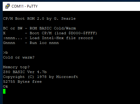
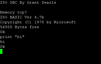
After downloading, we are rewarded with a very welcome sight.
Hitting enter in PuTTY doesn't work so we still have stuff to fix to get the Serial input to work but we're making great progress debugging in a relatively short time.
Let's set a breakpoint in the USB receive function in main( ). The function looks like:
        if (0u != USBUART_GetConfiguration())
        {
            /* Check for input data from host. */
            /* Only do the check if the buffer is already empty */
            if ((0u != USBUART_DataIsReady()) & (USB_To_Z80_RxBytes_count == 0))
            {
                /* Read received data and re-enable OUT endpoint. */
                USB_To_Z80_RxBytes_count = USBUART_GetAll(buffer);
                if ((USB_To_Z80_RxBytes_count == 1) & (checkSerialReceiverBusy() == 0))     // Input 1 character immediately
                {
                    sendCharToZ80(buffer[0]);
                    USB_To_Z80_RxBytes_count = 0;
                }
            }
        }
We set the breakpoint on the line with:
USB_To_Z80_RxBytes_count = USBUART_GetAll(buffer);
Pressing return in the PuTTy window caused the break to happen so we received data from the USB. The variable USB_To_Z80_RxBytes_count is 0 since we have not yet received any data (prior to this point). The variable USB_To_Z80_RxBytes_count shows that 1 byte was received as should also be expected. This matches the first condition of the line however the second condition is probably a problem.
if ((USB_To_Z80_RxBytes_count == 1) & (checkSerialReceiverBusy() == 0))If you remember in the earlier log I made a pure guess about how the RTS should work and I think I may have been wrong. Let's look at the function and single step through it.
///////////////////////////////////////////////////////////////////////////////
// uint8 checkSerialReceiverBusy(void) - Check the Serial port receiver status
// Returns:
//  0 if the port can take another character
//  1 if the port is busy and can't take another character

uint8 checkSerialReceiverBusy(void)
{
    if ((M6850_Ctrl & M6850_INT_RTS_MASK) != M6850_RTS_HI__INT_DIS)
    {
        return(1);
    }
    return (M6850_Status & SIO_CHAR_RDY);
}
Sure enough when we single step it shows the return(1) path being taken. So the PSoC isn't able to send data to the Z80. The problem looks like the not equal. The variable M6850_Ctrl is set to 0x96 and when ANDed with the mask 0x60 will be:
b'1001 0110
b'0110 000
=
b'0000 0000
Sure enough that looks like the problem but the fix is easy enough.if ((M6850_Ctrl & M6850_INT_RTS_MASK) == M6850_RTS_HI__INT_DIS)Setting the debugger to breakpoint at the start of this function and single stepping shows the return(1) isn't happening, which is good.
The next line has:
return (M6850_Status & SIO_CHAR_RDY);The M6850 has a value of 0x02 in M6850_Status and 0x1 in SIO_CHAR_RDY. I should change the variable name of the second variable to M6850... Thes two ANDed together will return 0 which should indicate that the port is ready to receive characters. The main( ) function will now call:
sendCharToZ80(buffer[0]);Looking at buffer[0] shows a 0x20 which makes me think I hit a space and not an enter. Let's keep stepping through the code to see what else is wrong. The function has:
void sendCharToZ80(uint8 rxChar)
{
    M6850_DataIn = rxChar;                                          // Put the char into the buffer
    M6850_Status |= SIO_CHAR_RDY;                                   // Rx Character Available
    if ((M6850_Ctrl & M6850_INT_RTS_MASK) != M6850_RTS_LOW__INT_EN) // Only set IRQ if it is enabled from the WR1 bits
        IO_Ctrl_Reg_Write(IO_Ctrl_Reg_Read() | 0x04);               // Set IRQ* line
}
Ah, now we are getting to the interrupt code. Let's see what the register values are before we go through this code.
- M6850_DataIn has 0x20 (the space I wrongly hit)
- SIO_CHAR_RDY is 0x01 - will set the receiver ready bit in the status register
- M6850_INT_RTS_MASK is 0x60 (it's a constant and doesn't change)
- M6850_Status is 0x20 which we initialized it to earlier. It should be 0x21 after we execute that line
The next line is executed to set the interrupt to the Z80 in the PSoC code as it should be. We'd need to be connected to the hardware with a scope or analyzer to see this happen, but we have seen this work with the SIO code. And the code returns as it should to main( ).
It's likely now that the problem is in the interrupt acknowledge cycle. Our guess that the vector should be 0xFF could be the problem. Let's set a breakpoint on the Interrupt ack code and see if the Z80 tries to do an interrupt acknowledge cycle. And sure enough that's the next breakpoint that is hit. That shows the next problem - which is hopefully the last problem since we are pretty far in the chain of events at this point.
Here's the code with the problem.
///////////////////////////////////////////////////////////////////////////////
// void M6850ReadIntReg(void) - Read the Interrupt vector

void M6850ReadIntReg(void)
{
    Z80_Data_In_Write(0xFF);
    IO_Ctrl_Reg_Write(IO_Ctrl_Reg_Read() & 0x7F);   // Clear IRQ* line
    ackIO();
}
The IO_Ctrl_Reg is inside the PSoC and has d1 as the interrupt line. However, I thought it was the interrupt status register in the M8650. It should be the same as the SIO code since it's part of the PSoC design not part of the M6850. The SIO has:
IO_Ctrl_Reg_Write(IO_Ctrl_Reg_Read() & 0xFB); // Clear IRQ* lineThat did the trick! We are now rewarded with the keyboard working and BASIC running.
That was a bit of work to get 56KB of SRAM (instead of the 48K of the previous build) but it should be a good porting guide.
-
6850 Emulation with a PSoC (Part 3)
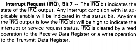
10/20/2019 at 16:37 • 0 commentsIn this log we will look at interrupts for the M6850. [Edit: this is a helpful page to understand the three interrupt modes supported by the Z80. Grant's code uses Interrupt Mode 1]. We left the compilation broken for interrupts and we need to fix those by creating the code and handing the differences vs the SIO. We also don't know exactly how Grant is handling interrupts. We do know from Grant's source code that he's apparently using them for receive and not for transmit. One difference between the Z80 peripheral chips and M6800 family parts like the M6850 is that there is no interrupt vector produced for the M6850 type of part.
The Z80 handles the lack of interrupt vector by having a special vector of 0xFF for devices which are not present. This seems to rely on the data bus floating high. We can probably do better and send out a 0xFF with a proper interrupt acknowledge cycle. Let's make this assumption and see if it works.
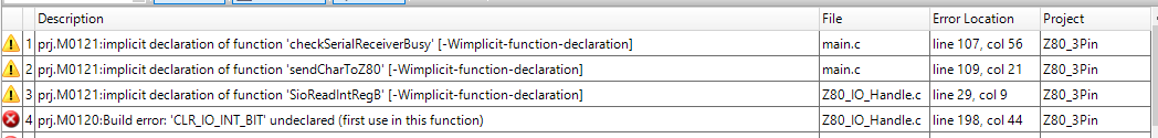
The errors that the compiler is producing now are both related to missing functions/values since they are not yet implemented for the M6850.
The SIO reads the value of the Interrupt vector from one of the control registers. As noted there's no such register in the M6850 so let's fix that. The error is coming out of the Z80IOHandle code:
    if ((ioCrtlRegVal & IACK_MASK) == IN_IACK_CYCLE)
    {
        SioReadIntRegB();
        return;
    }
Set the #define to conditionally remove the SIO code when the SIO is not used.
The SIO code for the routine is:
///////////////////////////////////////////////////////////////////////////////
// void SioReadIntRegB(void) - Read the Interrupt vector

void SioReadIntRegB(void)
{
    Z80_Data_In_Write(SIO_B_WR2);
    IO_Ctrl_Reg_Write(IO_Ctrl_Reg_Read() & 0xFB);   // Clear IRQ* line
    ackIO();
}
Z80_Data_In_Write(SIO_B_WR2) - returns the interrupt vector to the SIO. The next line clears the interrupt source. We still haven't set the interrupt anywhere so we will need to deal with that, but let's create a flag after we make the equivalent function for the M6850.
is not defined but we need to replace it with an the proper bit for the M6850. According to the data sheet this is bit 7 of the status register.
For the M6850 the code looks like:
///////////////////////////////////////////////////////////////////////////////
// void M6850ReadIntReg(void) - Read the Interrupt vector

void M6850ReadIntReg(void)
{
    Z80_Data_In_Write(0xFF);
    IO_Ctrl_Reg_Write(IO_Ctrl_Reg_Read() & 0x7F);   // Clear IRQ* line
    ackIO();
}
After adding the function prototype to the Z80_Emul.h file the only compiler error is:
So we are still missing an interrupt #define. That is used in a function in Z80_IO_Handle.c:
void ackIO(void)
{
    IO_Ctrl_Reg_Write(IO_Ctrl_Reg_Read() | CLR_IO_INT_BIT);
}
That is one of the #define values in Z80_SIO_Emul.c. It controls the interrupt hardware from the PSoC to the Z80, so it would be better added to the Z80_IO_Handle.h file. After doing that the PSoC compiles without error.
As a rough measure the M6850 emulator file is 114 lines long as compared to the SIO emulator file which is 444 lines. This shows just how easy it is to create relatively simple peripherals in the PSoC. It's made even easier in this instance since we have a Serial UART emulator already in the SIO software.
In the next log we will see what we missed and fix it so the code runs.
-
6850 Emulation with a PSoC (Part 2)
10/20/2019 at 16:16 • 0 commentsIn the last log we got the basic functions in place to emulate a M6850 ACIA UART with the PSoC controller used on this card. We left a few details open but the code compiled without error so we've got a good place to fill in the details here. Hopefully, the serial transmit and receive functions will work as-is.
The status and control register handler needs some work. The receive part of the status register might just work since it's in the same bit and has the same meaning as the SIO.
Hardware Handshake Handling
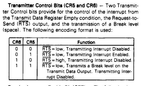
In particular, we've been ignoring the differences between the SIO and M6850 where it comes to dealing with RTS. The SCC had a single bit and the M6850 has two bits. Grant's intmini.asm file has the answer for RTS values. These are possibly the hard coded values that Grant writes to the control register to toggle RTS on and off.
RTS_HIGH        .EQU     0D6H
RTS_LOW         .EQU     096H
In fact, these are only different in the two relevant bits D6 and D5.
RTS_HIGH sets D6..D5 to b'10.
RTS_LOW sets D6..D5 to b'00.This correlates to RTS high and RTS low for the two cases . He sets Transmit Interrupt Disabled in both cases. This means we don't probably need to generate interrupts for transmits. That's consistent with Grant's monitor code in his 9-chip design.
This also means we don't need to have all that many side effects in the control register write routine. In fact the routine doesn't need to do anything other than set the value in the status register since it's being set in another routine. The RTS bit is in SIO_A_Ctrl2 so lLet's look at the routine which uses this value. That function is inside the Z80_SIO_emul.c file and for the SIO has:
///////////////////////////////////////////////////////////////////////////////
// uint8 checkSIOReceiverBusy(void) - Check the SIO port A receiver status
// Returns:
//  0 if the port can take another character
//  1 if the port is busy and can't take another character

uint8 checkSIOReceiverBusy(void)
{
    if ((SIO_A_Ctrl2 & SIO_RTS) != SIO_RTS)
    {
        return(1);
    }
    return (SIO_A_RD0 & SIOA_CHAR_RDY);
}
That is called from main( ) as a function so we can replace that function directly with one for the M6850. Here's what it looks like for the SIO.
                USB_To_Z80_RxBytes_count = USBUART_GetAll(buffer);
                if ((USB_To_Z80_RxBytes_count == 1) & (checkSIOReceiverBusy() == 0))     // Input 1 character immediately
                {
                    sendCharToZ80(buffer[0]);
                    USB_To_Z80_RxBytes_count = 0;
                }
I think it would be smart to replace the specific name of checkSIOReceiverBusy with a more generic value specific to this function. Also, we didn't get a compile error so the compiler must be including the SIO code and we want that removed. The find-replace in all uses is easy and produces this as the prototype:
uint8 checkSerialReceiverBusy(void);Adding #ifdef USING_SIO around the SIO code will remove it from conditional compilation and we should get a list of functions we need to create for the M6850 when we compile the code. After that we get a list of missing functions:
Some of these are real but some are missing #includes. We expected the checkSIOReceiverBusy call to be missing but we need to do something with the other 3 functions. They are SIO specific and may or may not need to be replicated for the M6850. First, let's make sure that the M6850 is also conditionally included by bracketing the code with the appropriate #define. Once we do that the compiler warnings/error list surprisingly drops. This implies that there are implicit declarations from the SIO although they are indicated from the Z80_IO_Handle file. I will ignore them for now and look at them later. For the moment we need to deal with the function at hand. From the SIO we see that the function is like this:
uint8 checkSerialReceiverBusy(void);Adding this as a stub function to the 6850 emulator .c and .h files should remove the compilation error. The header for the function from the SIO emulator has the following:
///////////////////////////////////////////////////////////////////////////////
// uint8 checkSerialReceiverBusy(void) - Check the SIO port A receiver status
// Returns:
//  0 if the port can take another character
//  1 if the port is busy and can't take another character
We want the function for the M6850 to do the same thing so the calling function just works. But the bits are different. In the SIO the function looked at a single bit in the control register.
uint8 checkSerialReceiverBusy(void)
{
    if ((SIO_A_Ctrl2 & SIO_RTS) != SIO_RTS)
    {
        return(1);
    }
    return (SIO_A_RD0 & SIOA_CHAR_RDY);
}
In the M6850 we want to look at both bits and return the proper value. We made the $defines earlier for these values but since Grant is only using 2 let's also add a comment with that note to the #defines.
#define M6850_INT_RTS_MASK          0x60
#define M6850_RTS_LOW__INT_DIS      0x00
#define M6850_RTS_LOW__INT_EN       0x20    // Not used by Grant's 7-chip code
#define M6850_RTS_HI__INT_DIS       0x40
#define M6850_RTS_LOW__INT_DIS_BK   0x60    // Not used by Grant's 7-chip code
The RTS polarity always confuses me but it's easy enough to swap values if the result doesn't work. RTS is normally the handshake on the request to send out to this host but in this case the RTS is between the PSoC and the Z80. The function appears to a have a dual use since it also checks the receiver has a character flag so let's leave that as well. Here's what the code looks like when adapted for the M6850.
///////////////////////////////////////////////////////////////////////////////
// uint8 checkSerialReceiverBusy(void) - Check the Serial port receiver status
// Returns:
//  0 if the port can take another character
//  1 if the port is busy and can't take another character

uint8 checkSerialReceiverBusy(void)
{
    if ((M6850_Ctrl & M6850_INT_RTS_MASK) != M6850_RTS_HI__INT_DIS)
    {
        return(1);
    }
    return (M6850_Status & SIO_CHAR_RDY);
}
The calling code uses the function as:
                USB_To_Z80_RxBytes_count = USBUART_GetAll(buffer);
                if ((USB_To_Z80_RxBytes_count == 1) & (checkSerialReceiverBusy() == 0))     // Input 1 character immediately
                {
                    sendCharToZ80(buffer[0]);
                    USB_To_Z80_RxBytes_count = 0;
                }
            }
That removed the compile error for checkSerialReceiverBusy( ) but we still have an error for sendCharToZ80( ). Let's fix that next. For the SIO that looked like:
///////////////////////////////////////////////////////////////////////////////
// void sendCharToZ80(uint8 rxChar) - Send a character to the Z80 by placing it
// into the SIO_A_DataIn register and making the RxCharacterAvailable active.

void sendCharToZ80(uint8 rxChar)
{
    SIO_A_DataIn = rxChar;                          // Put the char into the buffer
    SIO_A_RD0 |= SIOA_CHAR_RDY;                     // Rx Character Available
    if ((SIO_A_WR1 & 0x18) != 0x00)                 // Only set IRQ if it is enabled from the WR1 bits
        IO_Ctrl_Reg_Write(IO_Ctrl_Reg_Read() | 0x04);   // Set IRQ* line
}
The equivalent code needs the SIO_A values changed and bits adjusted. We can also look at the control register bits to see if interrupts are enabled and take the proper action. Here's the appropriate changes for the M6850.
///////////////////////////////////////////////////////////////////////////////
// void sendCharToZ80(uint8 rxChar) - Send a character to the Z80 by placing it
// into the SIO_A_DataIn register and making the RxCharacterAvailable active.

void sendCharToZ80(uint8 rxChar)
{
    M6850_DataIn = rxChar;                                          // Put the char into the buffer
    M6850_Status |= SIO_CHAR_RDY;                                   // Rx Character Available
    if ((M6850_Ctrl & M6850_INT_RTS_MASK) != M6850_RTS_LOW__INT_EN) // Only set IRQ if it is enabled from the WR1 bits
        IO_Ctrl_Reg_Write(IO_Ctrl_Reg_Read() | 0x04);               // Set IRQ* line
}
We still get compile errors but they all relate to interrupts. The next log will take a look at interrupt handling for the M6850.
-
Emulating the 6850 With a PSoC
10/20/2019 at 15:00 • 0 commentsThis should be the final piece of work to get Grant's 7-chip Z80 design to run on this hardware.
This is arguably the "hardest" part of the port since the 6850 emulator does not yet exist. I've gone through the front end details of creating Z80 peripheral chips in a lot of details for the PIO (although the series is not yet complete) so I will spare the details here. Here's the first log of that series (Z80 Peripheral Emulation Guide for the PSoC). Since the 6850 is more or less a very cut down version (not really a version) of the SIO we will start from that design, clone it, and change the functions that need changes to match.
The significant differences between the SIO and the 8650 include:
Feature SIO 6850 Ports 2 1 Command/Status Interface Complicated requiring a write then read or write cycle Simple with single control/status location Interrupts Uses Interrupt Acknowledge Interrupts but no Interrupt Acknowledge hardware Modify Z80_IO_Handle.c
We've already put #define conditional selection in this file to remove the SIO so we just need to clone that for the 6850 so let's start by copying that code and deleting what we don't need. Also, we need to use the proper #define USING_6850 to select the code when there's a 6850 being emulated. That should all happen inside the HandleZ80IO() function. That looks like this:
#ifdef USING_6850
        case M6850_D:
            if (ioCrtlRegVal == REGULAR_READ_CYCLE)             // regular read cycle
            {
                M6850ReadData();
                return;
            }
            else if (ioCrtlRegVal == REGULAR_WRITE_CYCLE)      // regular write cycle
            {
                M6850WriteData();
                return;
            }
            break;
        case  M6850_C:    // Control register
            if (ioCrtlRegVal == REGULAR_READ_CYCLE)             // regular read cycle
            {
                M6850ReadStatus();
                return;
            }
            if (ioCrtlRegVal == REGULAR_WRITE_CYCLE)      // regular write cycle
            {
                M6850WriteCtrl();
                return;
            }
            break;
#endif
Of course, as seen by four yellow exclamation boxes, we now broke the compilation since we've created a bunch of function calls to handle the Z80 access which don't yet exist.
Let's go create the four routines we need to handle these conditions. If we are careful enough the functions in main which call these handlers will still work. If we need to we can add some additional conditional compilations to handle them. In all likelihood we will have to modify the calling routines given that the SIO is interrupt driven for receive and this one may be different (yet to look at the details enough to see - it may be nearly the same). At the very least, interrupt acknowledge cycles will need to be different.
Low Level 6850 Handler
To do this, create two new source files in PSOC Creator (Z80_6850_Emul.c and .h). Liberally copy the pieces from the SIO equivalent and change what is necessary. Leave as much as possible the same to minimize changes to calling routines. Generally speaking, this means to replace the SIO_A with M6850_ in most places.
There are two lines we have to pay particular attention to. These determine which bits are used for the calling routines to test receive character ready and set RTS. For the SIO, these lines are:
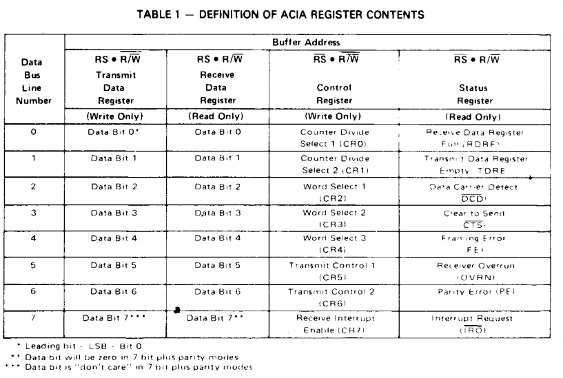
#define SIOA_CHAR_RDY   0x1
#define SIO_RTS 0x2
It's a bit hard to read in the datasheet but here's the values of the registers in the 6850:
The status register bit 0 is receiver data full. That's convenient since that's exactly what we have for the SIO so we won't change that #define value. But there's no bit which directly sets the RTS and we do need hardware handshake for flow control since the Z80 is much slower than a USB block transfer. The control register in the 6850 handles the RTS in a slightly different manner:
We'll have to look closer at Grant's assembly code INTMINI for the answer on how these bits need to be set but for the moment let's just make a mask and define the bits for the four patterns. This will replace the RTS code above and may necessitate some changes in the main( ) calling code.
The top of the .c file now looks like:
#include <project.h>
#include "Z80_6850_emul.h"
#include "Z80_IO_Handle.h"

#define SIOA_CHAR_RDY               0x01
#define M6850_INT_RTS_MASK          0x60
#define M6850_RTS_LOW__INT_DIS      0x00
#define M6850_RTS_LOW__INT_EN       0x20
#define M6850_RTS_HI__INT_DIS       0x40
#define M6850_RTS_LOW__INT_DIS_BK   0x60

volatile uint8 M6850_Ctrl;
volatile uint8 M6850_Status;
volatile uint8 M6850_DataOut;
volatile uint8 M6850_DataIn;
Next, let's make stubs for the four missing routines. Since the data ready flag is in the same place the Serial receive code can be easily created by copying it from the SIO and changing the variable names. The status bits are the same.
///////////////////////////////////////////////////////////////////////////////
// M6850ReadData(void)- Z80 is reading data from Serial Port

void M6850ReadData(void)
{
    Z80_Data_In_Write(M6850_DataIn);
    M6850_Status &= 0xFE;                              // No Rx Character Available
    ackIO();
}
The Serial output routine is similarly pretty easy.
///////////////////////////////////////////////////////////////////////////////
// void M6850WriteData(void) - Send a single byte from the Z80 to the USB

void M6850WriteDataA(void)
{
    uint8 buffer[64];
    uint16 count = 1;
    while (0u == USBUART_CDCIsReady());
    buffer[0] = Z80_Data_Out_Read();
    USBUART_PutData(buffer, count);
    ackIO();
}
The read status function is much simpler than the SIO since it does not use indirection and only returns the single status value. It no longer gets called from the routine which passes it the register offset so the passed value changes to a void. In fact, it becomes nearly trivial although it may require clearing a flag later on (probably not since reading the data register has already cleared the receive character flag).
///////////////////////////////////////////////////////////////////////////////
// void M6850ReadStatus(void) - Read the Status registers

void M6850ReadStatusA(void)
{
    Z80_Data_In_Write(M6850_Status);
    ackIO();
}
Similarly, writing to the control register is much simpler since there aren't two steps to do the write. For now, we'll just include the basic operation of setting the variable remembering that we need to make control register writes perform the operation of the control (we'll touch this later on). Here's what the routine looks like (without adding the side effects of setting control codes).
///////////////////////////////////////////////////////////////////////////////
// void M6850WriteCtrl(void) - Write to the SIO Port A control registers

void M6850WriteCtrlA(void)
{
    uint8 regNum;
    M6850_Ctrl = Z80_Data_Out_Read();
    // TBD - This is where the side effects of changing control codes are handled
    ackIO();
}
Next, let's add the function prototypes for these operations to the .h file.
void M6850ReadData(void);
void M6850WriteData(void);
void M6850ReadStatus(void);
void M6850WriteCtrl(void);
Also, add this .h file to the growing list of peripherals in the Z80_IO_Handle.c file.
#include <project.h>
#include "FrontPanel.h"
#include "Z80_IO_Handle.h"
#include "Z80_SIO_emul.h"
#include "Z80_PIO_emul.h"
#include "Z80_6850_emul.h"
#include "Hardware_Config.h"
Running the PSOC Creator build we can see that this compiles without error. That's a great start and a good point to save the current build off to GitHub with a comment that it is WIP.
Remember this won't work as it currently is because we've not yet implemented the write control register function to add the side effects.
In the next part we'll go through the remaining details of 6850 emulation and try the code to see if it runs.
3-Chip Z80 Design
Combining a Z80 retro design with a modern PSoC CPU.