 land-boards.com
-
Building the 7-Chip Z80 Software
10/20/2019 at 13:49 • 0 commentsIn the last log we added conditional compilation flags that allow us to use other software builds. We were left with two undone tasks:
- Build the software
- Add 6850 emulation
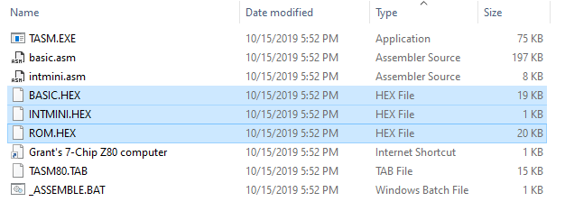
Let's tackle building the software. Grant's folder is a bit confusing since there are 3 .HEX files and we only need one file to create the image.
BASIC.HEX is the BASIC interpreter. INTMINI is a short interrupt handler for serial I/Ot that replaces the monitor code from the 9-chip design (which had both interrupt handler and monitor plus CP/M loader). ROM.HEX is the file that would be loaded into a ROM in the "real" design.
There's a couple of ways to get what we need out of this. One would be to compile the code. I was able to use TASM with my Windows 10 machine in an earlier log by running TASM under DOSBOX. There's also a newer TASM version which allows it to be assembled under Windows 10.
An easier way would be to use srec_cat to convert the .hex file to a C-Array. That is described in detail in this log. The command line is:
path_to_srecord\srec_cat ROM.hex -intel -o GS_7_CHIP_ROM.c -C-Array
That worked and created a C file with the following at the top:
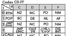
/* http://srecord.sourceforge.net/ */
const unsigned char eprom[] =
{
0xF3, 0xC3, 0xB8, 0x00, 0xFF, 0xFF, 0xFF, 0xFF, 0xC3, 0x9F, 0x00, 0xFF,
0xFF, 0xFF, 0xFF, 0xFF, 0xC3, 0x74, 0x00, 0xFF, 0xFF, 0xFF, 0xFF, 0xFF,
...
Chedking this code from the relevant Z80 Opcode chart:
Opcode 0xF3 is DIS INT (Disable Interrupts) and 0xC3 is JMP (jump). Grant's INTMINI has this code at the top.
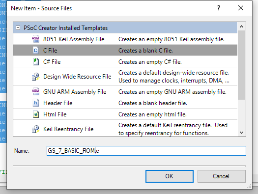
;------------------------------------------------------------------------------
; Reset

RST00           DI                       ;Disable interrupts
                JP       INIT            ;Initialize Hardware and go

;------------------------------------------------------------------------------
; TX a character over RS232

                .ORG     0008H
RST08            JP      TXA
So, it looks like the code matches just fine. Next, add a new file to the PSOC project: calling it GS_7_BASIC_ROM.c which we will place the newly generated code into.
After dropping the file and making a few changes, the top of this file looks like:
#include "Hardware_Config.h"

#ifdef GRANT_7_CHIP_Z80

const unsigned char gs7chip_basic_eeprom[] =
{
0xF3, 0xC3, 0xB8, 0x00, 0xFF, 0xFF, 0xFF, 0xFF, 0xC3, 0x9F, 0x00, 0xFF,
We have the #define conditional compile that gets set by the Hardware_Config.h file. The fact that the new code is not greyed out indicates that it will be included in the next PSOC build that is done. The inserted #define requires a #endif at the end of the file to close it.
#define EPROM_FINISH      0x00002000
#define EPROM_LENGTH      0x00002000

#endif

/* [] END OF FILE */
The array is renamed to be a name specific to this build. We could name all of the builds the same thing but it might be possible in the future to include multiple builds and select the build to run in some manner, so by pressing different front panel switches, so we are making this build specific to allow that possibility. This does mean that we need to add to the SRAM loading software for each specific build.
That is done inside the function that loads the software in the ExtSRAM.c file.
////////////////////////////////////////////////////////////////////////////
// void loadSRAM(void) - Load the SRAM on the card with the ROM code
// Initial code build is monitor plus BASIC code

void loadSRAM(void)
{
    uint32 charCount;
    uint32 SRAMAddr = MONITOR_START;
    volatile uint8 dataVal;
    for (charCount = 0; charCount < MONITOR_LENGTH; charCount++)
    {
#ifdef GRANT_9_CHIP_Z80
        dataVal = monitor_basic_eprom[charCount];
#endif
#ifdef GRANT_7_CHIP_Z80
        dataVal = gs7chip_basic_eeprom[charCount];
#endif
        WriteExtSRAM(SRAMAddr,dataVal);
        SRAMAddr++;
    }
}
We also need to add the definition to the top of the ExtSRAM.c file:
#ifdef GRANT_9_CHIP_Z80
extern unsigned char monitor_basic_eprom[];
#endif
#ifdef GRANT_7_CHIP_Z80
extern unsigned char gs7chip_basic_eeprom[];
#endif
At this point the software builds in PSOC Creator but if we run it there will be no output.
In the next section, we will write the code to emulate the 6850 inside the PSoC.
-
Supporting Other Software Builds
10/20/2019 at 13:11 • 0 commentsI want to be able to support any software build I find "out there". I started with Grant Searle's 9-chip Z80 design and got that working well.
The next step is to make it easy to add other builds. I could just spawn a new PSoC project but that means any improvements to the basic code itself need to get propagated into the previous builds and that's painful.
Instead, I added conditional compilation using #define, #ifdef to select the different options.
Here's how it's layed out. I put all of the conditional directives into one single file, Hardware_Config.h. This file breaks into separate sections.
The first section contains global hardware #defines. These map to the hardware used on the card itself. If there's no front panel it gets removed from the compilation. Same for the expansion MCP23017 I2C expander.
// Global choices based on hardware used/not used
// To include the function comment out the undef and use the include
//#undef USING_FRONT_PANEL        // Assume no front panel
#define USING_FRONT_PANEL     // Use front panel
//#undef USING_EXP_MCCP23017      // Assume no MCP23017 I2C I/O expansion part
#define USING_EXP_MCCP23017   // Use MCP23017 I2C I/O expansion part
The next section is a set of #undef for the hardware that has been emulated. For now, this is the SIO which works and the PIO which is a work in progress. This is where new emulation would be added. They are specifically included (undoing then undef) if they are in the software build used.
// These are the Z80 peripherals
// Assume none of the supported I/O peripheral chips are used
// They are included in the specific builds if the build software uses them
#undef USING_PIO
#undef USING_SIO
The next section defines which software build is being used. So far, only Grant's 9-chip software is included. Only one image can be selected at a time. To add another build #undef the other builds and #define the new build.
// Select the build here.
//  Only 1 build at a time is supported.
//  All other builds are set to undef
//#undef GRANT_9_CHIP_Z80
#define GRANT_9_CHIP_Z80
The next section is specific to the software build itself. This is the values for Grant's 9-chip design. Similar sections need to be added for new builds. This breaks down into two sections. The first is the memory map of the program and the second is the I/O space memory map.
// defines for building Grant Searle's 9-chip Z80 design
#ifdef GRANT_9_CHIP_Z80
    #define MONITOR_START       0x00000000      // EEPROM loads to address 0
    #define MONITOR_LENGTH      0x00004000      // 16K build
    // I/O Space Address Map follow
    #define USING_SIO
        #define SIOA_D              0x00
        #define SIOA_C              0x02
        #define SIOB_D              0x01
        #define SIOB_C              0x03
    #ifdef USING_FRONT_PANEL
        #define FR_PNL_IO_LO        0x18    // decimal 24
        #define FR_PNL_IO_LO_MID    0x19    // decimal 25
        #define FR_PNL_IO_HI_MID    0x1A    // decimal 26
        #define FR_PNL_IO_HI        0x1B    // decimal 27
    #endif
    #ifdef USING_EXP_MCCP23017
        #define PIOA_D              0x20
        #define PIOA_C              0x22
        #define PIOB_D              0x21
        #define PIOB_C              0x23
    #endif
#endif
Notice that the SIO uses a #define which undos the previous #undef. But, the Front Panel was a global value set at the start section.
Adding in Support for Grant's 7-Chip Build
Grant has a build with 7-chips. It uses less memory space for the program. Grant's 9-chip design has an 8K monitor and an 8K BASIC leaving 48K of RAM for programs. Grant's 7-chip design has an 8K ROM which just has BASIC (no monitor or CP/M support).
Let's make the changes/additions to the config file to support Grant's 7-Chip build.
The first complication is that Grant's 7-Chip build uses a 6850 UART in place of the SIO. We don't currently have an emulator for the 6850, but let's ignore that for the moment. The 6850 UART is much simpler to emulate than the SIO chip since it only has a single control and single status register so it should be easy to emulate the part.
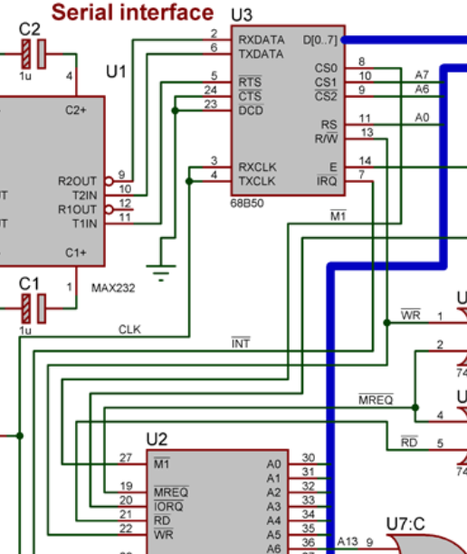
For now, let's just find the address map for Grant's 7-chip design. The 6850 has three chip select lines and one address select line. Here's the piece of Grant's schematic which has the Z80 and 68B50 UART.
From this we can see that:
- A7 = 1 (CS1)
- A6 = 0 (CS2*)
- M1* = 1 (CS0)
M1* determines if the Z80 is doing an I/O operation or an interrupt acknowledge. This is set up to not do interrupt acknowledgements from the Z80 peripheral. This makes sense since the 6850 is a 6800 family member and doesn't do interrupts in the Z80 style where the peripheral chip drives the Interrupt vector. At first glance this implies that Grant's code must be polled instead of interrupt driven. However, Grant hooks up the IRQ* line to the Z80 INT* line. So he may be using the default vector of 0xFF that the Z80 uses when there's no interrupt acknowledgement. We'll have to look at his code closer to see.
Grant's memory map leaves off quite a few address lines so it's necessary to look into his memory map to see what addresses he uses for the 6850. From Grant's page:
I/O Map

00-7F   Free (128 input and 128 output ports)
80-81   SERIAL INTERFACE (minimally decoded, actually covers locations 80 to BF)
C0-FF  Free (64 input and 64 output ports)
So this is relatively simple and matches the schematic (of course, since Grant is careful in his documentation).
First, let's start assuming we are not using the 6850 (since it is software specific):
// These are the Z80 peripherals
// Assume none of the supported I/O peripheral chips are used
// They are included in the specific builds if the build software uses them
#undef USING_PIO
#undef USING_SIO
#undef USING_6850
Then let's #undef the 9-chip design and add a build option for the 7-chip version of the software:
// Select the build here.
//  Only 1 build at a time is supported.
//  All other builds are set to undef
//#undef GRANT_9_CHIP_Z80
//#define GRANT_9_CHIP_Z80
#define GRANT_7_CHIP_Z80
Next, clone the 9-chip specifics and modify them for the 7-chip build.
Grant's Memory Map (program space) for the Z80 is:
Memory Map

0000-1FFF   8K ROM
2000-FFFF   RAM (56K)
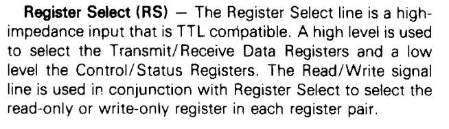
The 6850 Register Select line is connected to the CPU A0 line. The data sheet shows:
So address 0x80 is the control/status address and 0x81 is the data registers.
The #define block looks like this:
// defines for building Grant Searle's 7-chip Z80 design
// http://zx80.netai.net/grant/z80/SimpleZ80.htm
#ifdef GRANT_7_CHIP_Z80
    #define MONITOR_START       0x00000000      // EEPROM loads to address 0
    #define MONITOR_LENGTH      0x00002000      // 8K build
    // I/O Space Address Map follow
    #define USING_6850
        #define M6850_C              0x80       // Control/Status register
        #define M6850_D              0x81       // Data
    #ifdef USING_FRONT_PANEL
        #define FR_PNL_IO_LO        0x18    // decimal 24
        #define FR_PNL_IO_LO_MID    0x19    // decimal 25
        #define FR_PNL_IO_HI_MID    0x1A    // decimal 26
        #define FR_PNL_IO_HI        0x1B    // decimal 27
    #endif
    #ifdef USING_EXP_MCCP23017
        #define PIOA_D              0x20
        #define PIOA_C              0x22
        #define PIOB_D              0x21
        #define PIOB_C              0x23
    #endif
#endif
This builds in PSOC Creator but we are missing two pieces. The first is the new ROM image. The second is the 6850 emulator. We'll do these two in following logs but for now we've added the basic pieces we need to have multiple builds and haven't broken the 9-chip design software build.
-
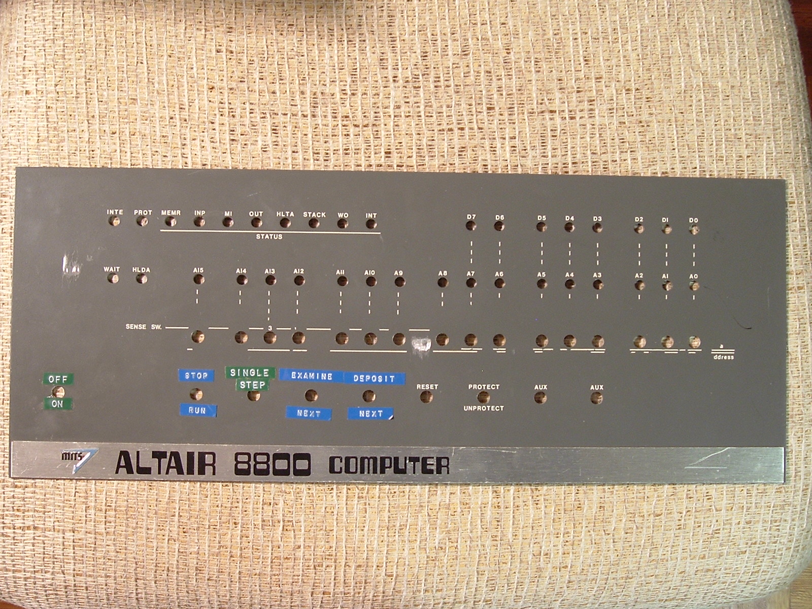
Altair Front Panel Switches
10/17/2019 at 10:47 • 1 commentI am tempted to rename the Front Panel switches to match the Altair 8800 Front Panel.
![]()
My current legend vs the Altair is:
- INCAD matches EXAMINE/NEXT (down)
- LDADR matches EXAMINE (up)
- STINC matches DEPOSIT
- I don't have a DEPOSIT/NEXT. This is used to fill memory with a constant
- RUN matches RUN
The Altair bunches keys in octal. I don't want that.
-
Z80 Peripheral Emulation (Part 4)
10/15/2019 at 23:06 • 0 commentsHere's where we really need to dig deep into the data sheet. Again, I suggest um0081 for the nitty gritty on how the PIO works.
The data says there are multiple modes for the part and that the part is largely used in interrupt driven applications. Of course this complicates the design for reasons previously mentioned. But to start with, is there a polled mode that can be implemented? Something that lets us blink a light or read a switch?
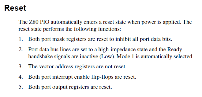
Initialization
One of the first things in the data sheet is what happens during power on initialization of the PIO. These registers are initialized as follows.
These actions can be done by creating a function that gets called before the Z80 gets pulled out of reset. I didn't explicitly create an initialization function for the SIO since the BIOS (defined as the Basic Input Output or monitor) initializes the registers it needs. It is a good practice to have a function to initialize the values. In the case of the PIO, the initialization code should also initialize the MCP23017. For instance, #2 above says that the GPIO pins should be set to high-impedance. For the MCP23017 parts this means setting them to inputs.
Perhaps an obvious question
Astute readers will note that the Front Panel uses the same MCP23017 parts. So we already have initialization code for the MCP23017. But there are important differences. One is that the MCP23017 is optional. Well, so is the Front Panel for that matter. The Front Panel has 8 bits as input (for the switches) and 8 bits of output (for the LEDs). This limits the drive current from the part. If all of the pins on a part were outputs then it would stress the drive current to drive 16 LEDs. So some values are "hard-coded" for the Front panels but need to be programmable for the MCP23017 that is used on the base board.
Conditional Inclusion of Optional Hardware
There are a lot of ways to deal with optional hardware. In the case of the external MCP23017 it's controlled by the I2C interface in the PSoC. Perhaps the PSoC could probe to see if the MCP23017 part is present? Something like an I2C port scan. That would allow the part to be installed or not installed.
Another way would be with #defines and conditional compilation.
A third way might be to create a new version of the PSoC project. Create Workspace Bundle under File is the way to do that. But that's painful since we'd end up with a lot of builds.
For now, I'll just install a part and deal with this later.
-
Z80 Peripheral Emulation (Part 3)
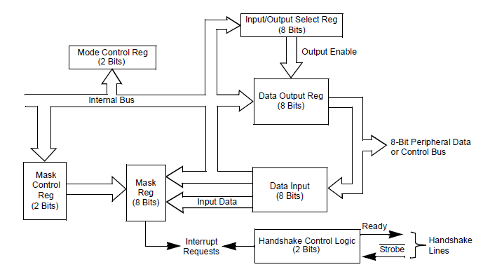
10/15/2019 at 22:06 • 0 commentsProbably one of the best references for the Z80 peripherals is um0081. um0081 describes the PIO starting on p 175. One of the more useful diagrams is the block diagram:
This shows the internal structure that the PIO has. Most importantly it shows the specific registers which need to be created as data values in the low level code contained in Z80_PIO_emul (.c and .h files). since they are all 8 bits values (or less in a couple of cases) they can be represented as uint8 types. These look like:
volatile uint8 PIO_Mask_Port_0;
volatile uint8 PIO_Vector_Address_Port_0;       // Mode 2 interrupt vector
volatile uint8 PIO_Interrupt_Vector_Port_0;
volatile uint8 PIO_Output_Register_Port_0;

volatile uint8 PIO_Mask_Port_1;
volatile uint8 PIO_Vector_Address_Port_1;
volatile uint8 PIO_Interrupt_Vector_Port_1;
volatile uint8 PIO_Output_Register_Port_1;
These values are defined as volatile since they could be changed by interrupt routines. They get placed into the .c file.
Digging further into the data sheet shows the bit fields of the registers and these are added to the .h file.
#define PIO_OP_MODE_0       0x00 // Output
#define PIO_OP_MODE_1       0x40 // Input
#define PIO_OP_MODE_2       0x80 // Bidirectional
#define PIO_OP_MODE_3       0xC0 // Control which bits are ins/outs
#define PIO_OP_DIR          0x01 // 1=input, 0-output

#define PIO_INT_EN_BIT      0x80 // 1=enable interrupts, 0-disable interrupts
#define PIO_AND_OR_BIT      0x40 // 1=AND, 0=OR
#define PIO_HIGH_LOW        0x20 // 1=monitor for high, 0=monitor for low
#define PIO_MASK_FOLLOWS    0x10 // Define mask bits follow
#define PIO_INT_CTL_WORD    0x07 // Signifies Interrupt Control Word
#define PIO_MASK_BITS       0xFF // Bit mask values

#define PIO_OP_MODE_MASK    0xC0 // Relevant bits
#define PIO_OP_MODES_WORD   0x0F // Relevant bits
We will probably tweek these values as we go along, but this is a good starting point. In the previous log we created the following function stubs which should be put into the .h file as function prototypes.
void PioReadDataA(void);
void PioWriteDataA(void);
void PioWriteCtrlA(void);
void PioReadDataB(void);
void PioWriteDataB(void);
void PioWriteCtrlB(void);
These also need to be added to the .c file and will be filled in as the functions are developed to handle each Z80 transfer. For now, just do something like this for each function:
void PioReadDataA(void)
{

}
The Z80_PIO_emul.h file should be added to the #includes at the top of the Z80_IO_Handle.c file so that it knows picks up the function prototypes.
#include <project.h>
#include "Z80_IO_Handle.h"
#include "Z80_SIO_emul.h"
#include "Z80_PIO_emul.h"
The include file gets added along with the other interfaces.
At this point the code compiles without error. Of course, we are missing the meat, but we have a solid skeleton for putting the meat onto.
In the next part we'll start looking at the details of the lowest level functions. What should happen when the Z80 reads the Status of Port A or writes the data of Port B?
-
Peripheral Emulation (Part 2)
10/15/2019 at 20:48 • 0 commentsThis log will take a look at the changes to the Z80_IO_Handle .c and .h files to support new Peripheral emulations. It can also serve (in part) as a porting guide to run other BIOS code (BIOS in this case being defined as the "stock" code such as ROM Monitors, BASIC language, etc).
Z80_IO_handle.h File
This contains the I/O space memory map from the perspective of the Z80 CPU. These are 8-bit addresses. Each physical port has it's own address. In the case of the SIO this is four addresses:
#define SIOA_D              0x00
#define SIOA_C              0x02
#define SIOB_D              0x01
#define SIOB_C              0x03
These are literally the addresses that are used by I/O routines. From assembly this is IN and OUT opcodes. From [NASCOM] BASIC this is the INP and OUT keywords. Other BASIC interpreters may use other keywords.
The address that needs to be assigned can often be found in the listing file for the stock BIOS code. Since this PIO example isn't working from a standard BIOS build, let's assign the ports. Physically, the PIO gets connected to A/B (Port select) and C/D (Control/Data) select lines. These are Z80 address bits in every instance I have seen. For the SCC, these get connected to A1 = C/D* and A0=B/A*. So, when A1 A0 = 0 0 this is the A port and Data.
Assuming the PIO gets connected in the same basic manner let's "hook" the PIO C/D to A1 and the B/A* to A0. That gives us four ports. Next we need to pick a base address. For the SIO, the base address is zero. We've already got the front panel assigned to 0x18-0x1A. Let's assign the PIO to 0x20-0x23. Of course this should be set to whatever the stock code is but we don't have a particular stock code for this instance (yet).
That translates to:
#define PIOA_D              0x20
#define PIOA_C              0x22
#define PIOB_D              0x21
#define PIOB_C              0x23
Notice how similar this is to the address map of the SIO and how easy it would be to move it. In fact, if we wanted to move the base address trivially, we could use another macro for the base and add an offset. But let's leave off such optimizations for now. They really are just polish on the apple.
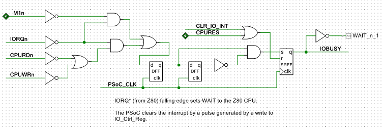
The other things in the file are the I/O control bits and some typical patterns. They tell us the details of the transfer type. The one of first interest is the IOBUSY_BIT. This is a bit which reflects the idea that an I/O (or interrupt) operation is in progress and that WAIT* has already been asserted to the Z80. It is made of a combination of the other bits but is a good kick-off point for knowing that a transfer is in progress and the PSoC needs to do something. Here's how it's made:
When there is an I/O operation in progress, IORQ* gets asserted (low) by the Z80 and CPURD* or CPUWR* are also asserted. That sets the first Flip-Flop. Another PSoC clock later the second flip flop gets set. The activating edge sets the R-S Flip Flop and gets sent out as WAIT* to the Z80.
Interrupt acknowledgements are done with M1 and IORQ but without a CPURD* or CPUWR*. They also assert WAIT* to the Z80.
The WAIT* stays asserted until the PSoC clears it with a pulse on the CLR_IO_INT line.This hardware function is monitored by the loop in main( ) which does nothing more than call the function to handle I/O when it sees IOBUSY set.
        if ((IO_Stat_Reg_Read() & IOBUSY_BIT) == IOBUSY_BIT)
        {
            HandleZ80IO();
        }
The HandleZ80IO( ) function is in Z80_IO_Handle.c . The function first looks at the control bits from the Z80 to determine if the request is an interrupt acknowledgement. If so, it handles the interrupt acknowledgement by sending out the contents of the interrupt vector register to the Z80. Presently, this is only hooked to the SIO Part B Interrupt vector register but if there are other sources (and the PIO could be one such source) it would need to be checked and priority determined (actually it is predetermined and can be found in the interrupt chain on the schematic for the stock design). Then the right interrupt vector would need to be returned. This is another spot where the PSoC can provide some flexibility that other approaches might not be able to incorporate. For instance, the PSoC could ensure that no interrupt source gets starved by higher priority interrupts. Or it could implement a tiered approach where high priority interrupts (like timers) always get serviced first and lower priority sources are handled in another way (maybe, round robined).
The next thing that the HandleZ80IO( ) function has is the switch statement that calls the lower level function. There is a case for every single address defined in the #defines of the memory map earlier. Further, there can be separate calls to read or write functions depending on whether read or write is being asserted by the Z80.
Since the ports are similar to the SIO from the perspective of the Z80 we'll just copy the functions and change SCC to PIO. All the work of emulation will be done at the lower level but this will ensure that the same sort of calls are made as the SIO already uses.
This reduces down to a handful of functions being added. Here's the prototypes for these functions.
void PioReadDataA(void); void PioWriteDataA(void); void PioWriteCtrlA(void); void PioReadDataB(void); void PioWriteDataB(void); void PioWriteCtrlB(void); -
Z80 Peripheral Emulation Guide for the PSoC
10/15/2019 at 17:55 • 0 commentsOn this board, Z80 peripherals are emulated by the PSoC. This is done using a combination of hardware and software in the PSoC. The PSoC connects to all of the Z80 address and data lines as well as the Z80 control lines and in the process acts as an I/O Space mapped peripheral part to the Z80.
The peripherals are typically done from PSoC elements. For instance, the SIO (Serial Input/Output) device is emulated and mapped to the USB interface inside the PSoC. When you insert a USB interface onto the schematic in PSOC Creator, the PSoC automatically generates the API routines to talk to its own hardware. The job of emulating peripherals then falls to the software running on the PSoC. The software takes the read/write requests from the Z80 and maps them to the PSoC peripheral. This can be setting control/status registers and/or reading/writing data. Thus, the PSoC hardware takes care of the low level communications.
This log will show the steps to create a peripheral for the PSoC. This was demonstrated in part for the USB-Serial in previous logs. This log will demonstrate the steps to use an MCP23017 external to the PSoC as an equivalent to the Z80 Parallel I/O (PIO). Some of the PIO functions can be emulated and others can't due to the hardware limitations of the MCP23017.
The Datasheet
The first step is to read through the datasheet for the Z80 peripheral you want to emulate. This will indicate how many control and status registers there are. It will also suggest the functions needed by the emulation code.
Map to Internal PSoC or External Hardware
The next step is to map the functions that the Z80 peripheral chip provides to the internal (to the PSoC) or external (connected to the PSoC through some pins. There aren't enough pins on the PSoC to do the PIO function so an external part is used. For the PIO this looks like:
Z80 PIO                 MCP23017
2 of 8-bit I/O ports    2 of 8-bit I/O ports
Pins set to input       Pins set to input
Pins set to output      Pins set to output
Pins set to bidirec     Emulate bidirec pins under control
Two control lines/port  No equivalent
Parallel interface      Parallel interface to PSoC
                        I2C interface to MCP23017
Speedy (Z80 IO speed)   I2C speed (slower)
So, it looks like the MPC23017 can do most of the basic functions minus handshakes and could possibly do the handshakes under the right set of controls (taking up some of the bits used by the 2nd parallel port, for instance).
Whether or not this is sufficient is application dependent. In the case of the PSoC emulating SIO over USB the cost (in time) is relatively small and the gain is significant (the same connector that powers the card also provides the USB signals).
In the case of the MCP23017 emulating a PIO chip, the slow speed of the I2C interface to the PSoC might be an issue. but it might be possible to use the MCP23018 and the SPI bus which is significantly faster and could connect to the 4-pin header on the card.
Also, the automatic ready/strobe of the PIO could be emulated at the cost of slower I/O since the PSoC would be tied up with handing those control/status lines and would limit I/O during that time.
Simple applications, like reading a joystick or blinking an LED could easily be accommodated by this approach.
If the MCP23017 is run at 400 KHz (around 40 KB/sec) and it takes 4 I2C transfers to do a read/write then it's running at a speed of around 10,000 transfers a second. That's not nearly as fast as the PIO, but certainly fast enough to read joystick switches.
Files To Be Created
Let's work from the bottom up here. A couple of C and header files need to be created that will contain the lower level functions. Create files to describe the lowest level of the part. For this example, that's two files; Z80_PIO_emul.c and Z80_PIO_emul.h .
The .h file contains the #defines which describe the register and bits. The .c file will contain the low level code that handles I/O.
Update the Z80_IO_Handle Functions
The Z80_IO_Handle contains the memory map and calls the lower level emulation functions. For this step, add the peripheral to the memory map in the Z80_IO_Handle.h file as #defines.
The functions to call the lower level code get added to the HandleZ80IO( ) loop in the Z80_IO_Handle.c file. These handlers are coded in a switch-case statement so the case values need to be added for the port addresse(s) of the peripheral. The address #defines from the .h file allow these values to be easily moved around in the memory space (if needed) as a compile time option. If they needed to be dynamically configured they could be stored in variables although this would likely affect compiler optimizations negatively. The need to have I/O ports at re-configurable locations seems like a remote possibility.
We'll dig into the details of these files in the next logs.
-
Current Status
10/15/2019 at 11:12 • 0 commentsAt this point everything that as initially targeted is working.
- Grant's stock Monitor and NASCOM BASIC code are running (call this BIOS in this case)
- Programs can be dropped on Host terminal screen and downloaded at full (possible) speed over USB
- All communication is over USB
- SIO emulation by the PSoC works with Grant's code (not in the most general case, but a good start)
- Front Panel works for examining and altering memory as well as running the program in ROM
- and also can be accessed from the Z80 IO space as IN, OUT instructions (INP, OUT in BASIC)
The things which are not yet done are; CF card support and support for the MCP23017 I2C Port Expander. Also, no other build was tried.
Grant's code supports a Compact Flash (CF) card with hardware connections. Board has a header with 4 PSoC pins and Power/Ground. This could be connected to an SDHC or SD card and used in SPI mode. This would require understanding how Grant's code accesses the CF card.
The MCP23017 could emulate a PIO chip (at least to some degree). The only issue is that the PIO has support for handshake lines and the MCP23017 is just two 8-bit data ports. But the PSoC could easily do bit banging. Having some degree of emulation would be a useful goal but it might help to have some target application (BIOS)
-
Fixed SIO Receiver Overrun
10/15/2019 at 10:48 • 0 commentsGrant's code uses RTS to stop the host from sending serial data to the card until it is done processing the current characters.
I was ignoring the RTS line. Added in code to factor in the RTS when determining if the Z80 was ready for more SIO data and there are no more overruns on the SIO receiver (to the Z80).
This was a fairly easy change. Added a single condition to check RTS and return busy if the RTS indicated that the Z80 wasn't ready for more data:
uint8 checkSIOReceiverBusy(void)
{
    if ((SIO_A_Ctrl2 & SIO_RTS) != SIO_RTS)
    {
        return(1);
    }
    return (SIO_A_RD0 & SIOA_CHAR_RDY);
}
I can now drop programs into the PuTTY window and they are properly uploaded to the card.
Here's the BASIC code to write and read the front panel.
10 PRINT INP(24)
20 FOR I = 1 TO 1000
30 NEXT I
40 GOTO 10
100 FOR I = 1 TO 255
110 OUT 24,I
120 FOR J = 1 TO 1000
130 NEXT J
140 NEXT I
Lines 10-40 read the bottom row of switches. Lines 100-140 write the bottom row of LEDs. This is described in a previous log.
3-Chip Z80 Design
Combining a Z80 retro design with a modern PSoC CPU.
 When there is an I/O operation in progress, IORQ* gets asserted (low) by the Z80 and CPURD* or CPUWR* are also asserted. That sets the first Flip-Flop. Another PSoC clock later the second flip flop gets set. The activating edge sets the R-S Flip Flop and gets sent out as WAIT* to the Z80.