Ali
Ali-
Design Improvement Ideas
04/28/2020 at 01:00 • 0 commentsElectrical Setup
Additional design improvements can also be integrated into the design’s electrical setup that can improve the pump’s convenience and provide additional features. For example, the electrical setup can be modified to incorporate a potentiometer knob. The knob can be rotated to adjust the input signal to the microcontroller which can automatically equate to changing the initially set flow rate value in the code. As a result, this will allow the user to adjust the flow rate during operation without the need to reconfigure the microcontroller’s code.
An addition of a liquid crystal display (LCD) screen can allow the user to view details about the pump when running, such as the currently set flow rate or the operating time remaining.
Furthermore, a toggle switch can be included to override the controller’s code and act as a safety off switch. It can alternatively be used to select between the controller’s codes. This can allow the pump to have separate functioning modes such as high and low speeds or small and large volumes. Enabling the user to quickly interchange between the modes depending on the desired task without the need to reconfigure the controller’s code.
Design Optimisations
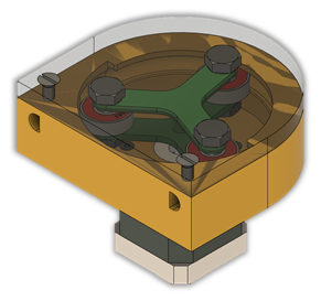
Additional design upgrades can be implemented to improve the durability and functionality of the pump. For example, a plastic cover that can be fixed onto the top of the pump, shown in the figure below, can provide protection to the pump’s components such as the tubing and rotor. It can also prevent unwanted objects from entering into the casing, which can impede the rotor or tubing and can cause damage to them or leakage. The purpose of having a transparent cover is to enable the user to quickly inspect the inside of the casing for any potential leakage, thus improving the chance of identifying faults before they develop further.
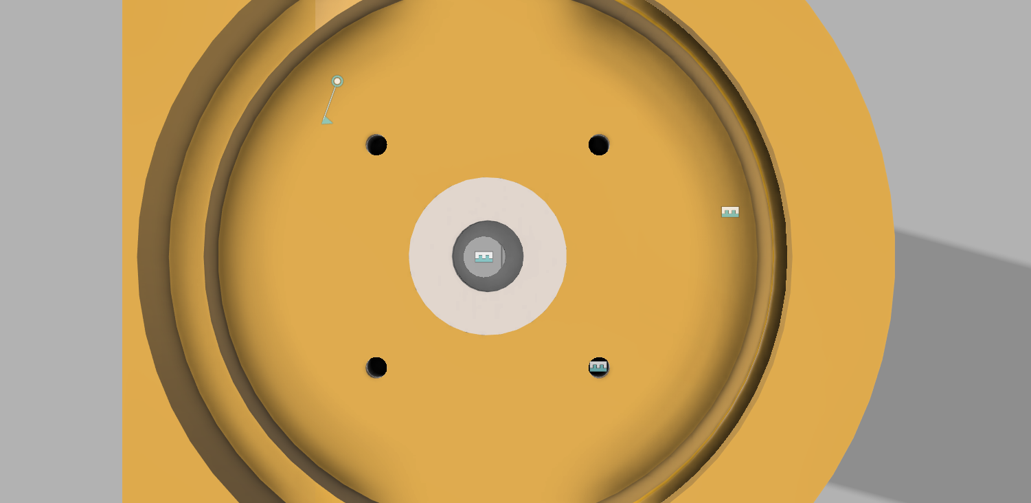
The number of inlet and outlet holes for the tubing can be increased, as shown in the figure below, from the current case where there is only a single inlet and outlet hole. This will allow the direction of the tubing to be adjusted according to the application’s need, which will reduce the risk of the tubing getting pinched due to sudden change in direction as it exits or enters the pump that can accelerate tubing wear.
Finally, a housing for the electrical components can be created to contain the microcontroller and other fragile electrical components such as the motor driver and capacitor. This will give the design further durability and increase the project’s portability as the entire housing can be simply moved instead of each component separately.
-
Performance Analysis
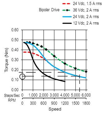
04/28/2020 at 00:56 • 0 commentsAn estimate of the flow rate of the pump can be approximated from the rotational speed of the rotors and the cross-sectional area of the tubing. The flow rate is dependent on the fluid’s viscosity, tubing inner diameter, and backpressure. Therefore, the flow rate was calculated for a low viscosity Newtonian fluid in a pump setup with negligible back pressure or fluid elevation. The rotor is designed to compress the tubing to a distance of 2mm between the rotor’s tip and the wall of the raceway. Since the thickness of the tubing is 1mm, it is assumed that, at the point of compression, the tube walls are in complete contact and seal off the fluid. This means that no fluid is leaked backwards towards the inlet and that the rotor moves a fixed volume of fluid contained in the tubing. The total volume displaced in one revolution was be obtained:
Volume per revolution = 0.000916 Litres
RPM for 1.5 L/min = 1637
Torque at maximum speed = 1.4N.cm
The output torque of the motor was obtained using the motor’s torque-speed curve shown in the curve above. The output value of the torque was found to be about 1.4N.cm which is smaller than the required torque. Therefore, the pump will not be able to operate at such high speeds with the proposed setup. The pump’s maximum operating speed is approximately 1200rpm which will result in a pump flow rate of around 1.1 L/min instead of 1.5 L/min.
-
Finite Element Analysis
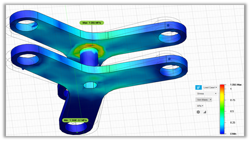
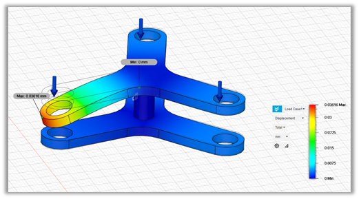
04/28/2020 at 00:51 • 0 commentsThe main component structurally analysed was the rotor as, based on previous prototypes, it is predicted to be a component highly susceptible to failure. The rotor was simulated under frictional loads transferred from the rollers that can likely initiate cracks in the rotor’s legs. However, the simulation estimated a factor of safety of 15, signifying that the rotor can withstand the frictional forces. Additionally, the maximum stress levels are at the centre of the rotor as shown in the figure below. This indicates that this area could be considered as the most likely to introduce failure, and as such should be regularly inspected during maintenance.
Furthermore, the weight of the attached components on the rotor was simulated, not only to identify if failure is possible from the weight, but also to investigate if the weight will elastically deform the rotor leg, consequently altering the position of the rollers which can then collide with the casing. The analysis concluded that the displacement due to the weight is approximately 0.04mm, which is negligible and should have insignificant effect on the roller’s position as shown in the figure below. Additionally, the factor of safety was found to be around 11, which indicates that the weight will not affect the integrity of the rotor.
-
Costing
04/28/2020 at 00:29 • 0 commentsThe cost of the pump was evaluated to assess the design’s feasibility. The costs of the microcontroller, motor driver and power supply were not included in the analysis as they will still be needed regardless of the pump selected.
Component
Quantity
Unit Cost (£)
Subtotal (£)
Casing
0.132kg
19.5/kg
2.57
Rotor
0.012kg
19.5/kg
0.234
NEMA 17 Motor
1
10.5
10.5
Tubing
1 m
1.40/m
1.40
Bearing
3
0.49
1.47
M3 bolt
4
0.05
0.20
M8 bolt
3
0.05
0.15
M8 Nut
3
0.08
0.24
Total
£16.76
-
COVID-19 Impact on Project
03/24/2020 at 16:06 • 0 commentsDue to the recent COVID-19 pandemic and health concerns my University has shut down all facilities and labs and as such I will not have the opportunity to construct my final design any time.
I have decided instead to try and run some computational simulation on the Design for various analysis to understand, test and improve my design further. I am very open to hear ideas and feedback from the community with regards to my design.
I will also try to temporarily fix the second prototype if possible and try to run practical tests on it as well.
PS: I will still upload the CAD files for the final design for anyone who is able to print them and it would be amazing if you can share the progress.
-
Final Design CAD Sketches
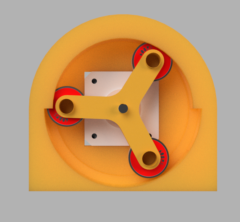
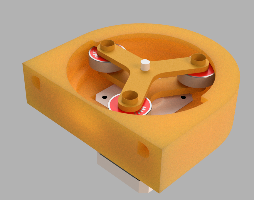
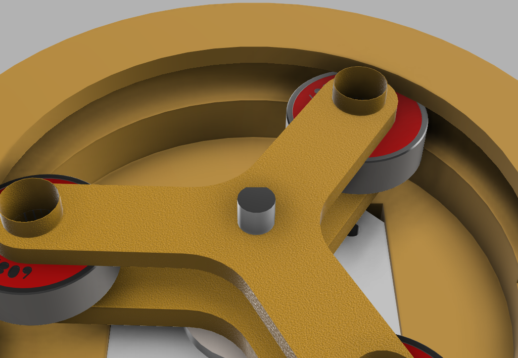
03/24/2020 at 15:58 • 0 commentsThe main features changed from Prototype 2 are:
1.Screw locations for the motor at the bottom of the casing. Allowing the motor to be easily removed and installed to the casing easily
![]()
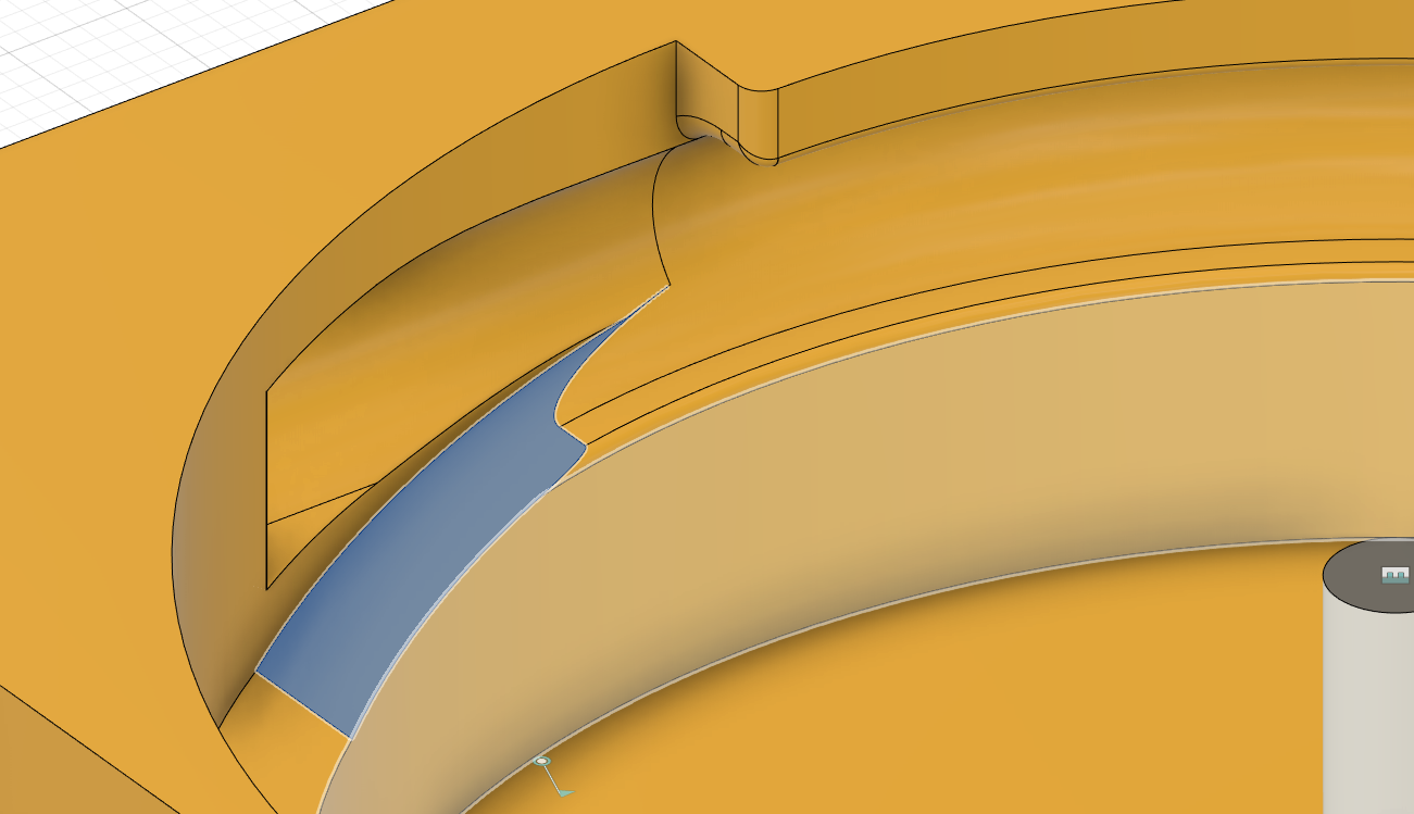
2. Fillets added to the sharp edges near the raceway to reduce the friction between the bearing and the walls of the casing
![]()
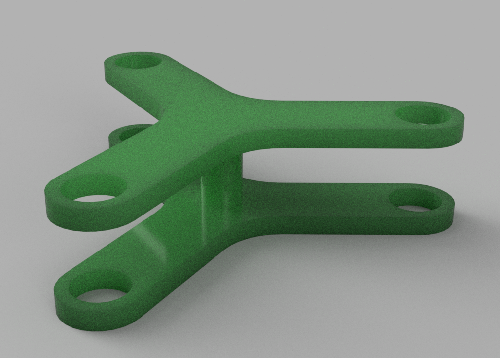
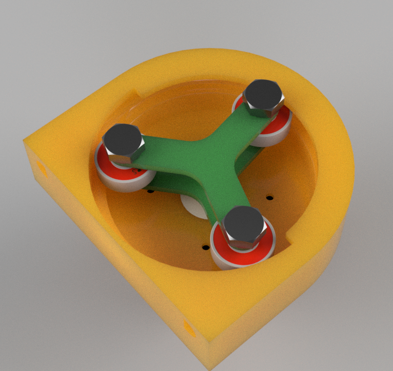
3. Combined bottom and top rotors together to become one part this will ensure the distance between them is maintained at the desired amount
![]()
4. Wedge feature include in the rotor to allow the attach to the motor shaft without the need of adhesion. This will not only allow the rotor to be removed when needed but also will offer better grip between rotor and shaft and prevent the shaft from rotating freely from the rotor
5. Nut and bolt to be used to hold the bearings in place instead of rod as it offers a stronger structure and does not require adhesive to stick to the rotors
![]()
Next Steps: I will next attempt to run various simulations on the design to validate its functionality.
-
Prototype 2: Testing
03/24/2020 at 15:16 • 0 commentsTesting:
Similar to Prototype 1, I tested this prototype using the same code that allows the stepper motor to continuously rotate.
Testing at max motor speed had the same issue as the previous prototype as the torque is still lower than required at max speed. See video below of motor vibrating and struggling to rotate.
However for this prototype, the motor was able to successfully pump fluid at lower speeds/ here is a video of the motor in operation ( with no tubing)
![]()
I used a latex tubing instead the previous silicone tubing as it was more flexible. Additionally, after testing several times the adhesive between the shaft and rotors was removed and as such the motor shaft began rotating independently of the rotor ( similar to what has happened to the first prototype)
i have also noticed that because the bearing height is not correct, they collide with a sharp edge in the raceway.
Verdict:
- From Prototype 2, I concluded that the size of the casing and tubing seem to be sensible for the motor's output and such will not be changed in the final design.
- Adhesive should not be used to glue rotor and shaft nor motor and casing as it makes it very difficult to disassemble.
- Maximum Motor speed should not be used as it significantly reduces the torque output and causes the components to rapidly vibrate that can then damage the structure.
- Need to add fillets to reduce sharp edges that slow down the bearings as they rotate.
-
Prototype 2: Construction
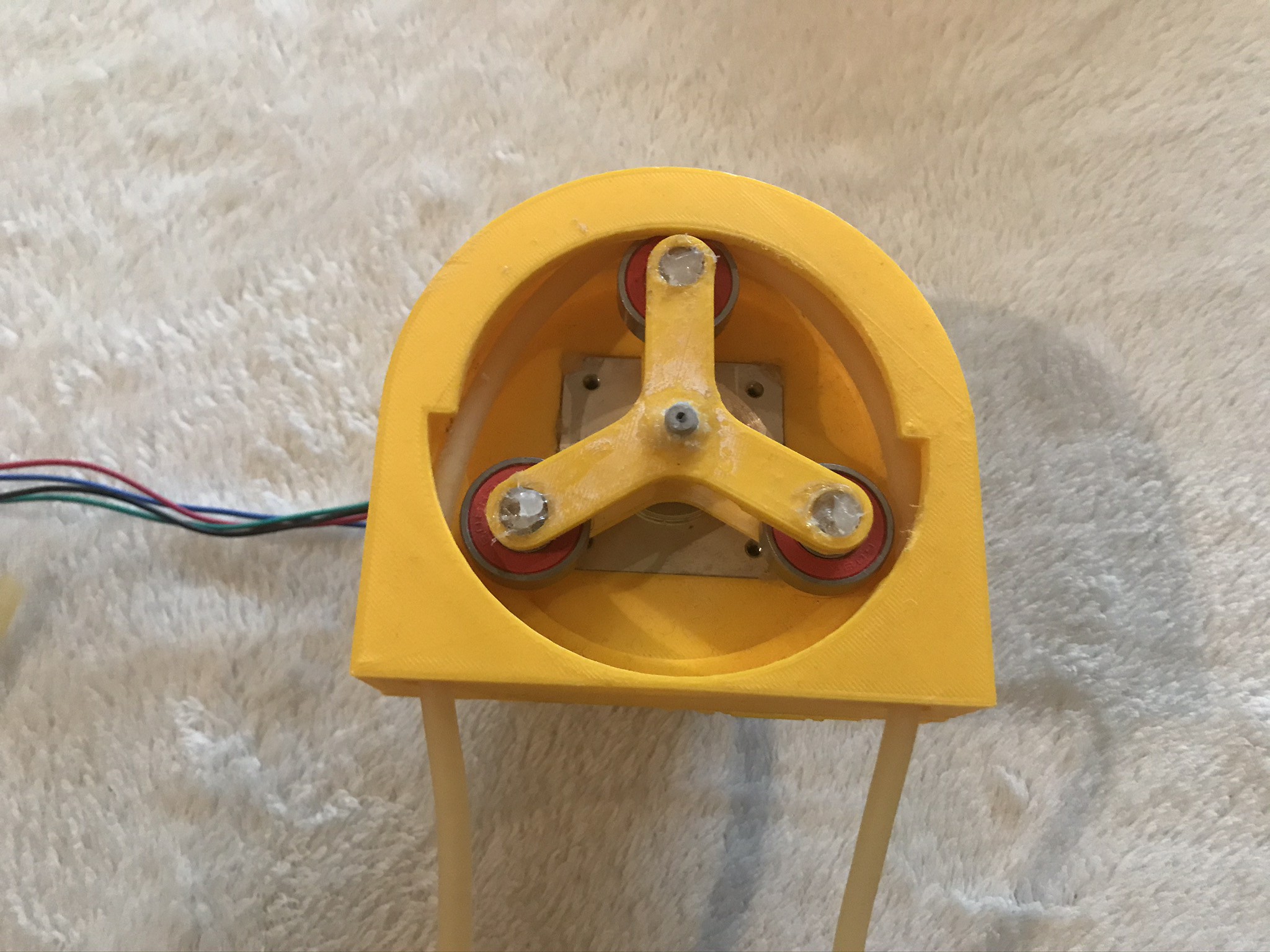
03/24/2020 at 14:48 • 0 commentsConstruction:
1. First, I 3D printed the casing and rotors as intended. However the bottom rotor's extrusions were not successfully printed and as such I had to make some final minute adjustments to the design.
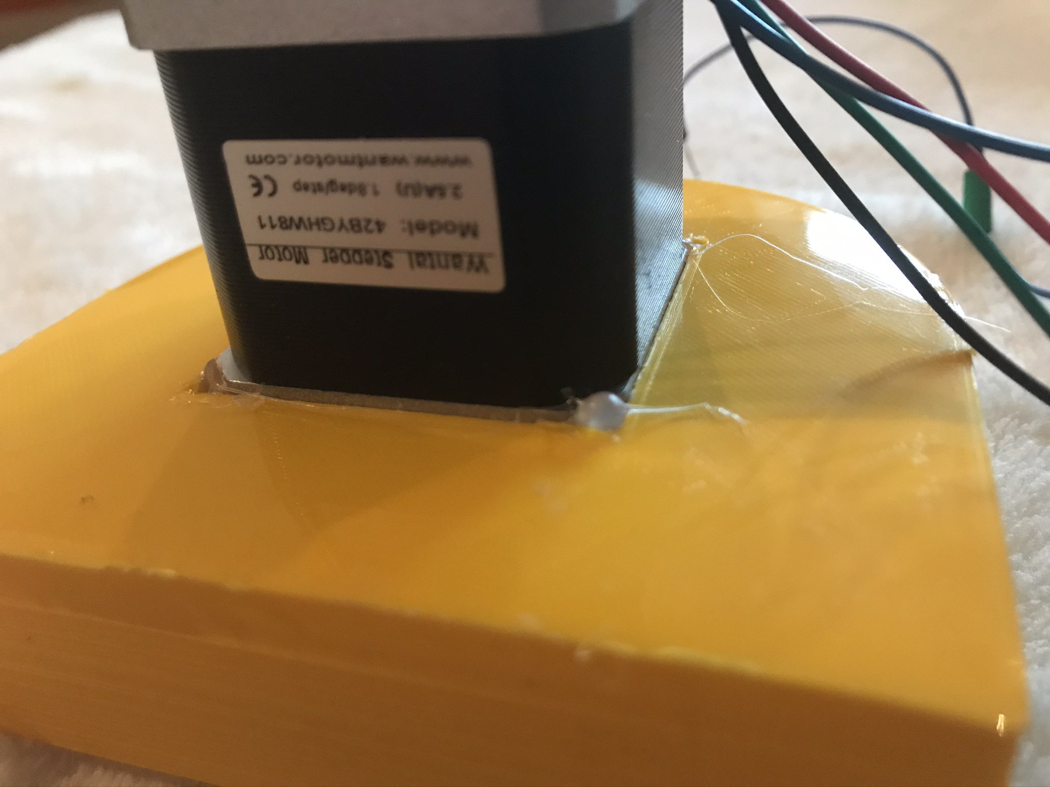
2. I attached the motor to the casing using adhesive ( glue gun) as shown below.
![]()
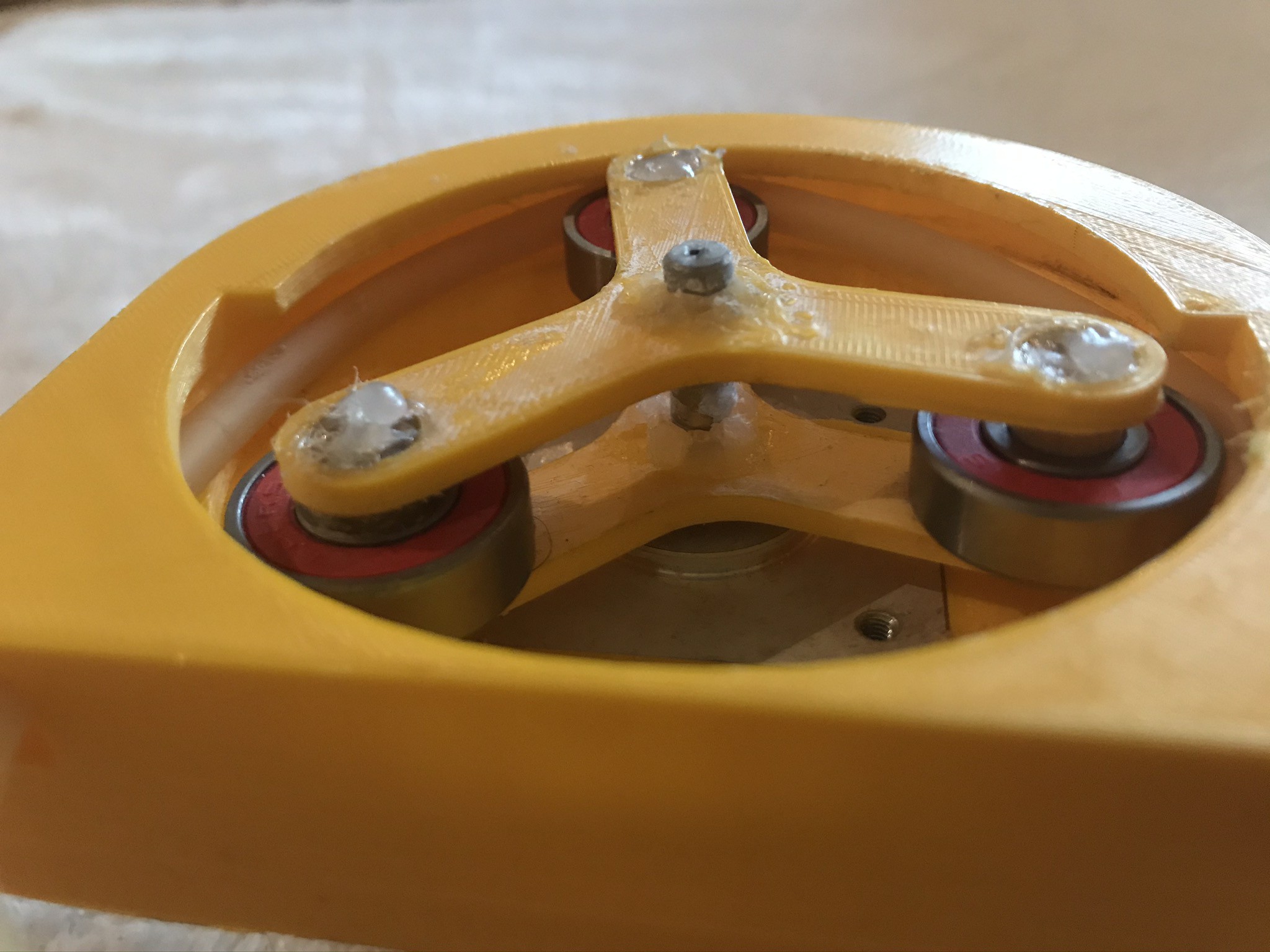
3. Then I carefully glued 8mm plywood rod in the bottom rotor and then inserted the rotor into the motor's shaft. The rotor's hole was tight enough to hold it in place on the shaft.
4. Then I carefully slotted the bearings into the rods.
5. lastly I aligned the top rotor with the rods and glued them together
6. Finally I glued the rotors with the shaft.
![]()
![]()
Conclusion:
- Using Adhesive to attach motor reduces the ease of disassembly in case a motor replacement is needed. It also reduces reduces the accuracy when horizontally aligning the motor.
- Using Plywood as supporting rods for the bearing increases time and difficulty of assembly.
- Was difficult to align the rotors at the correct height as designed.
-
Prototype 2 Design
03/24/2020 at 13:17 • 0 commentsPrototype 2:
After constructing and testing Prototype 1 a new redesigned pump was sketched. The new design's aim was to reduce the limitations and inefficiencies of the first prototype.
This was done through the following Features:
- Reduce diameter of rotors to reduce the torque required by motor.
- Reduce overall height of casing to reduce material required and printing time.
- Reduce thickness of rotors to reduce weight.
- Increase motor cut tolerance to ease assembly.
- Reduce raceway diameter to fit smaller tubing.
Below are some CAD sketches for the new design:
![]()
![]()
![]()
-
Prototype 1 Testing
03/23/2020 at 19:12 • 0 commentsTesting:
First Trial:
At my first trial to run the pump, the motor's shaft was disconnected from the rotors and as such was rotating independently and the rotors remained stationary as shown below. To overcome this, I used adhesive to stick the shaft and rotor together to be able to run the tests.
![]()
Maximum Speed:
The pump was tested at the maximum speed to see if the rotors are able to rotate through the casing and understand the potential max volume flow rate possible. Once the motor was operated, the rotors started rapidly vibrating in place as shown in link below. I assume this is because the torque supplied by the motor at such speeds is not sufficient to overcome the frictional forces and moments the bearings experience from the casing's raceway.
https://vimeo.com/user110521159/review/400015830/37903e3764
Other Speeds:
However, what I quickly realized is that even at slower speeds the rotor had difficulties rotating smoothly and while this can be due to manufacturing errors causes the rotor and casing to contact, this meant that if a tube was added the rotor will not be able to rotate at all.
Verdict:
Conclusion from testing the prototype is that:
- Size of the pump is too big for the motor to provide a reliable torque
- Larger tolerance needed between rotors and casing
- Need to use more flexible tubing to reduce load required by motor
Peristaltic Pump for Beverage Dispenser
Design, build and operate a Peristaltic Pump