Redgeneral
-
Prototype C
01/24/2021 at 21:36 • 0 commentsProject resumes!
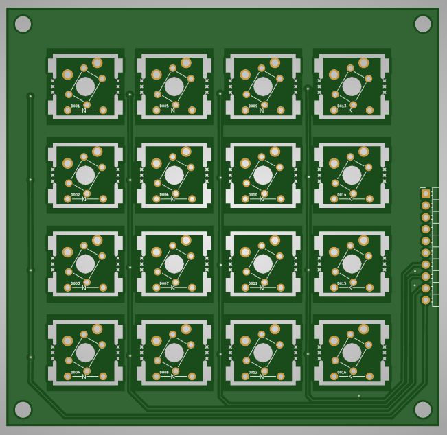
A new set of test PCBs has been ordered - a 4x4 Velocity Switch matrix with breakaway panels.
![]()
As the PCB manufacturer (JLCPCB) only does multiples of 5, this one design will be used for 3 purposes.
The Three (identical) PCBs in the stack:
A - breakaway squares are removed and the PCB becomes the plate holding the MX switches (far cheaper than a laser cut plate)
B - MX level - MX switches and diodes soldered
C - Small switch layer - LL1105AF065Q-ND switches and diodes soldered.
The original plan was to use a surface mount switch, but I just found surface mount too small for me to reliably solder. This is why prototype B failed.
So I switched to a THT switch, which helped the design:
- All components are now THT
- The slight increase in height between the B and C levels has allowed for a far simpler method to connected B and C to the control board.
This 4x4 test board will help to test the whole system (design and code) prior to the full size velocity keyboard PCB development.
Just waiting for the PCBs to arrive...
EDIT: JLCPCB have added an additional charge for the routing of the breakaways. In future the Plate will be its own separate PCB
-
Prototype B - Small section test (in progress)
11/15/2019 at 16:19 • 0 commentsStatus: In progress (PCBs arrived)
Purpose:- Small scale test of key mechanism (5x2 keys)
- Controller program test
- Responsiveness test
- USB midi functionality test
PCBs:
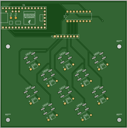
PCB 1 (Teensy, 74H595, 10 EVQQ2 switch, and male header):
![]()
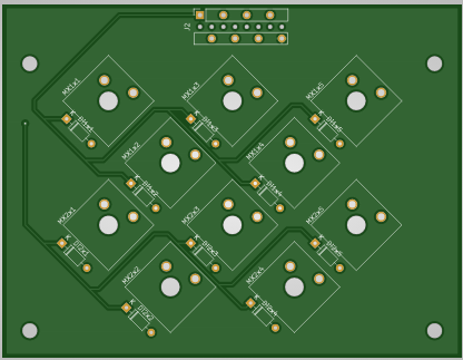
PCB 2 (10 MX type switches, and female dual entry header):
![]()
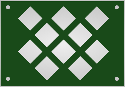
PCB 3 (Plate):
![]()
[PCB rendered by online pcb viewer]
Music notes
The test pcb should return the following notes:
B0 D#1 F#1 A#1 C#2 C1 E1 G1 B1 D2 -
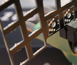
Prototype A - single key test
11/15/2019 at 16:18 • 0 commentsPurpose:
- Determine min and max distances between EVQQ2 pcb and the MX pcb - Achieved
- Confirm key mechanism works - Achieved
- Test possibility of reusing same PCB design for each level and plate - Feasible but not practical
Identical PCBs:
The Mitosis Keyboard aimed to reduce costs by using PCBs that could be used for multiple roles, such as the MX plate and MX PCB mount. Sections could be broken off to turn the PCB into a plate.
![]()
[Image source: Mitosis Keyboard - https://imgur.com/a/mwTFj ]
When a PCB design is ordered, often it is produced in sets of 5 copies. Costs could be reduced if the same PCB design could be used for each layer (EVQQ2 layer, MX layer, and Plate).
Unfortunately when I received the PCB, I was unable to remove the breakaway sections and so had to dremel them out.
In the end, although feasible, it would be very difficult to design for.
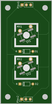
PCB render:
![]()
Note: diodes are the wrong way round on the design (oops), but have been soldered correctly instead.
Photos:
[Photos of assembled prototype to be added later]
-
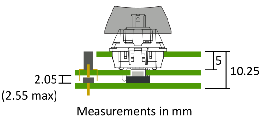
Key Mechanism
11/15/2019 at 14:32 • 0 comments![]()
Each key is made from two switches, with the velocity determined by the time difference between. The larger switch is a Cherry MX type, with the seeond being EVQQ2 type.
This key mechanism is based on the one seen at http://wiki.lvl1.org/Isomorphic_Keyboard
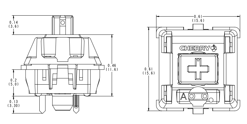
MX switch
![]()
[Image source: cherrymx.de/en/dev.html]
The MX internal switch mechanism contains a plunger that is stopped by a well that extends beyond the base. A hole is required in keyboard PCBs to accommodate this well.
By cutting off the well, the plunger is able to extend beyond the base and strike a switch below it.
The MX switch variant chosen is the Gateron White (a MX clone), due to the the low force required and silent operation.
The MX switches are held in place using a plate that the MX switches clip onto. Normally this plate would be laser cut, however a PCB without traces is used instead as it is cheaper. The holes for the switch body to enter are made during the PCB manufacturing.
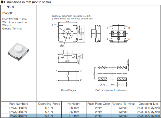
EVQQ2
![]()
[Image source: EVQQ2 datasheet]
The switch has a very low actuation force, so little resistance when pressed by the MX switch's plunger.
One problem with this switch is that is a surface mount component and so not easy to solder by hand.
Headers
- Male header on the EVQQ2 layer
- Dual entry female header on the MX layer
- Matrix columns shared between layers via headers
- MX row output passed to EVQQ2 layer (which also has the Teensy LC controller)
- Note: the space between PCBs means that the male header's plastic component must be smaller than usual
- Due to height of female header, the Plate cannot cover this header
Key caps
- DSA profile
- DSA keycaps are rated for all rows on a computer keyboard, so they all must have the same shape and no slope.
- Tonnetz keyboard requires all the keys caps to be identical without slope.
-
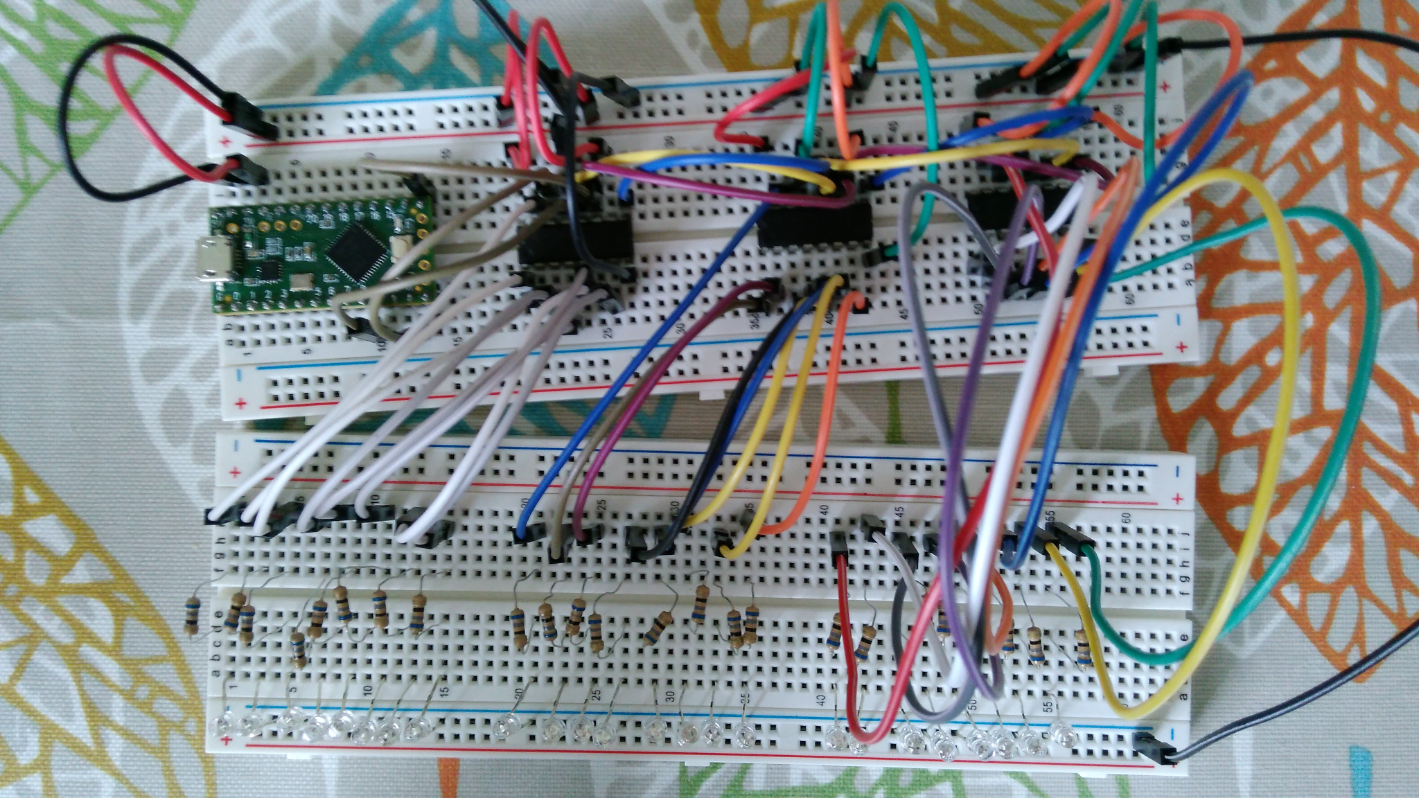
Column circuit test
10/20/2019 at 11:48 • 0 commentsThree 74HC595 chips will be used to drive the 24 columns of the keyboard's button matrix. I built a prototype on breadboard to ensure the circuit design and code were correct, As this was just a test of the columns, LEDs are used instead of buttons.
![]()
Code:
---------- more ----------// ----------------------------- // teensy 24 led columns - // cycles through to light up // one LED at time // ----------------------------- // connections to 74hc595 int latchPin = 8; int clockPin = 13; int dataPin = 11; // count int count = 1; int countTotal = 24; // shifting values byte patterns[8]={ B00000001, B00000010, B00000100, B00001000, B00010000, B00100000, B01000000, B10000000 }; // temp values byte tempA = B00000000; byte tempB = B00000000; byte tempC = B00000000; void setup() { // put your setup code here, to run once: // set serial pins to output pinMode(latchPin, OUTPUT); pinMode(dataPin, OUTPUT); pinMode(clockPin, OUTPUT); } void loop() { // put your main code here, to run repeatedly: //update and reset if (count<9){ tempA = patterns[count-1]; }else{ tempA= B00000000; } if (count<17 && count>8){ tempB = patterns[count-8-1]; }else{ tempB= B00000000; } if (count>16){ tempC = patterns[count-16-1]; }else{ tempC= B00000000; } //write to shift registor digitalWrite(latchPin,LOW); shiftOut(dataPin, clockPin, MSBFIRST, tempC); //3of3 shiftOut(dataPin, clockPin, MSBFIRST, tempB); //2of3 shiftOut(dataPin, clockPin, MSBFIRST, tempA); //1of3 digitalWrite(latchPin, HIGH); //wait delay(500); //loop variable count++; if (count>24){ count=1; } } -
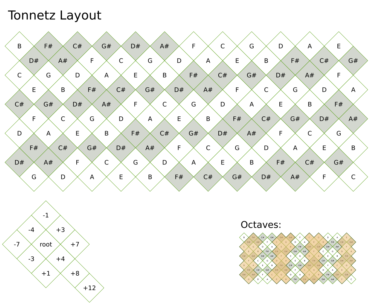
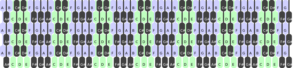
Tonnetz Layout
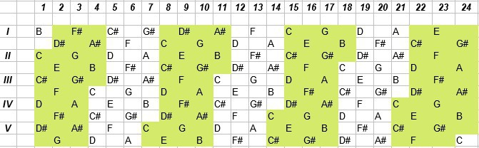
10/18/2019 at 20:54 • 0 commentsLayout:
![]()
Specifications:
- 7 Octaves + 2 Notes
- 120 keys : 86 Notes -> 1.4 Keys : 1 Note
The layout pattern loops - the bottom rows are repeated at the top of the next column along. For example, the F# and G at the bottom of column 2 are repeated at the top of column 3.
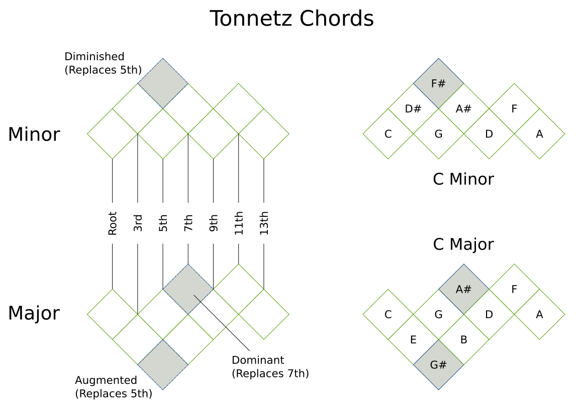
Chords:
![]()
With the chord keys being adjacent, it should be possible to two keys with the same finger. Entire length of of chord might be playable with just four fingers.
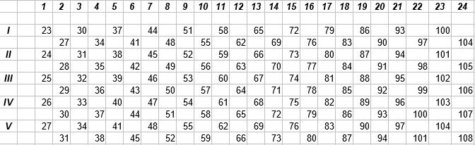
Octave map:
![]()
Midi note values:
![]()
Midi value for each key could either be calculated on the fly or stored in an array.
After comparing all the isomorphic keyboards, I chose the Tonnetz layout because:
- Compact
- Low key to note ratio - reduces weight
- Chord shapes seem reasonable - compact and requires fewer fingers
- Full 7 octaves
-
Alternative layouts
10/18/2019 at 12:07 • 0 commentsBefore starting work on this project, I considered several different isomorphic layouts
- Harmonic Table Layout
- Wicki-Hayden Layout
- All Fourths Layout
- Janko Layout
Below I show the layouts and major/minor chords of each and my reasons for not choosing them.
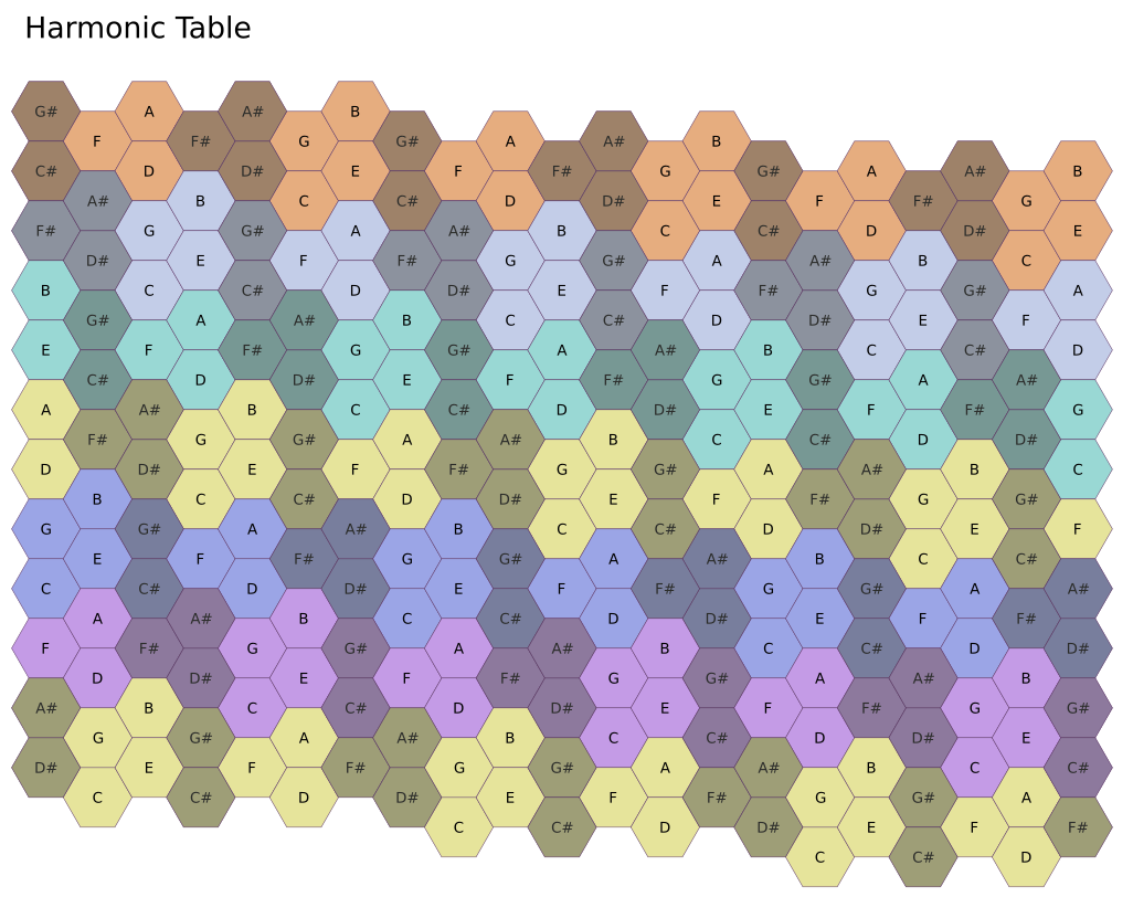
Harmonic Table Layout:
![]()
Specifications:
- 7 Octaves
- 252 keys : 84 notes -> 3 keys : 1 note
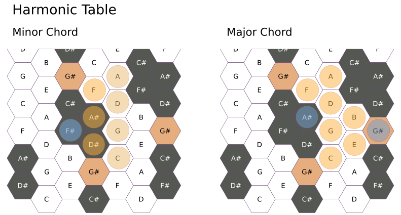
Chords:
![]()
[Blue coloured indicate alternative keys to change the type of chord - e.g. Diminished chord by using F# instead of G]
- Hexagonal keys allows for chords to be played with fewer fingers
- All key caps would have to be custom made
- Vertical chord patters did not seem very comfortable to play
This was my initial choice for a layout, but at 252 keys, I very quickly became apparent that the weight of the switches alone would be too much.
There was a commercially available keyboard using this layout called the Axis-64 by C-thru, but it has now been discontinued.
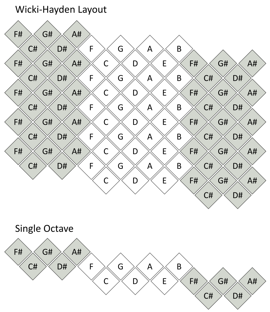
Wicki-Hayden Layout:
![]()
[Note columns of sharps on left are repeated on the right]
There are two general configurations:
- One tall keyboard - with the hands one above the other
- Two split keyboards - each hand has its own keyboard.
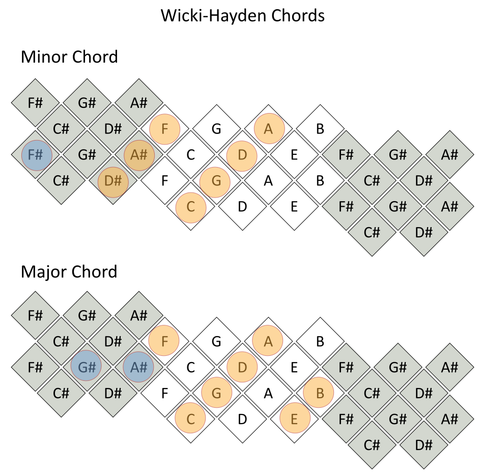
Chords:
![]()
I find these chord shapes really uncomfortable (especially the blue modifiers) - this is the deal breaker for this layout.
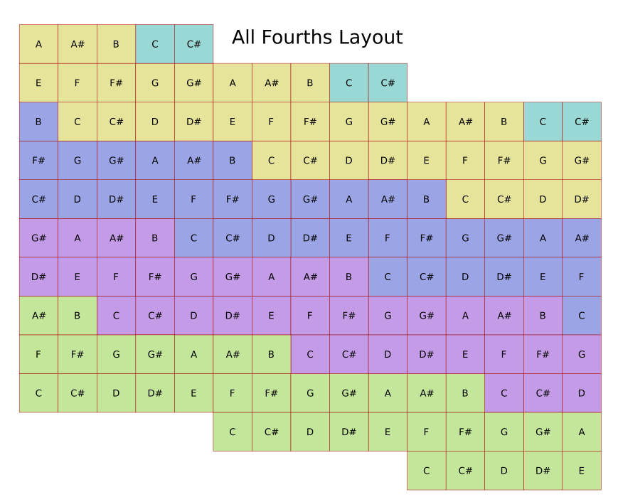
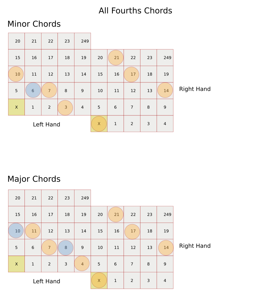
All Fourths Layout:
![]()
![]()
Specifications:
- 150 keys : 50 notes -> 3 keys : 1 note
- 4 Octaves
The All Fourths was a strong contender, but it's few octaves and large number of buttons were against it.
Janko:
![]()
[image from wikipedia]
For me the Janko is not suitable for several reasons
- Just as long and as heavy as a regular piano keyboard
- The chord shapes are not very pleasant for my hands
Janko keyboards are currently in production branded as Chromatone - https://chromatone.jp/
-
My interest in Isomorphic Instruments
10/14/2019 at 21:31 • 0 commentsMy drive to make an isomorphic keyboard comes from my limitations. I have painful joints that can make playing regular musical difficult.
- I can't hold items of any weight for long so that eliminates wind instruments, guitars etc.
- Playing percussion jolts the joints causing pain
- Limits to how wide I can spread my fingers without increasing pain - this means piano keyboards keys are just too far apart
- Stringed instruments often have very contorted hand shapes to hold down the notes - not pleasant on my hands
Using a grid of keys in an isomorphic layout should be better for me to play
- Keys closer together for less stretching
- Chord patterns that require less twisted hand shapes than a regular piano keyboard
- Potentially a smaller, lighter keyboard
-
It begins
10/14/2019 at 20:30 • 0 commentsProject work begins
TonnetzOne - Isomorphic Midi Keyboard
An isomorphic midi keyboard using the Tonnetz layout