Close
0%
0%

DTL binary clock

Using 50 year old DTL ICs to build a clock

Similar projects worth following
I had a handful of Motorola DTµL 900 series flip flops and gates and wanted to build something out of them for retro kicks

A DTL binary clock

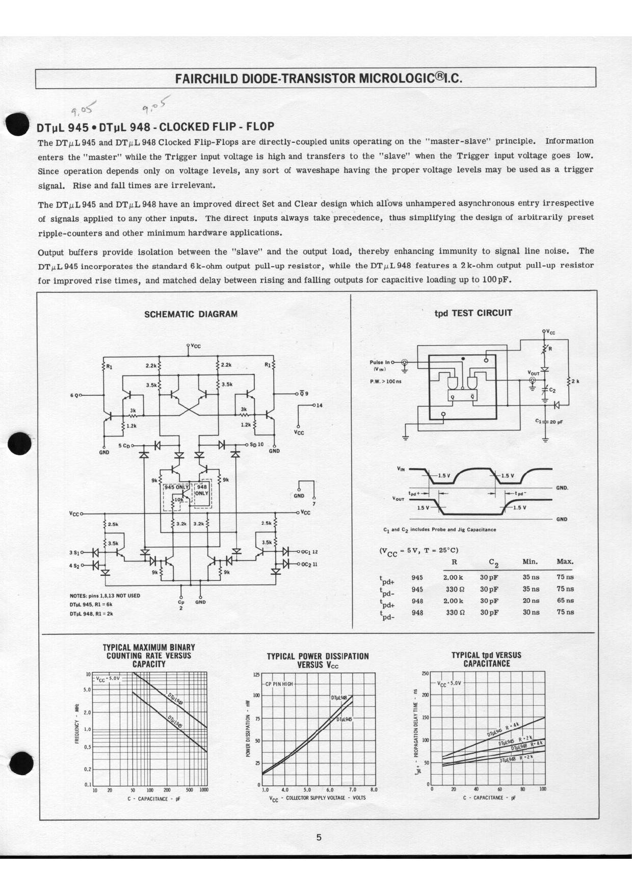
I found that I have a dozen DTµL945 master-slave flip-flops from about 50 years ago in my retro collection. These Diode Transistor Logic (DTL) chips are truly small scale integration. Even TTL packed 4 or 8 flip-flops to a package. What to do with them? Here is the data sheet for it.
Overview

The only viable project I could think of was a binary clock. I can't even do BCD hours and minutes, that requires more chips than I have. I can only do sexagesimal hours and minutes. 0-23 requires 5 bits, and 0-59 requires 6 bits. I also need a 2-input NAND gate to reset the hours at 24 and a 4-input NAND gate to reset the minutes at 60. I have the DTµL830 which has dual 4 input NAND gates. This has the same pinout as the TTL 7420, and in fact I used the library symbol for that. The LEDs are driven directly from the flip-flops.

Designing with DTL is very similar to designing with classic TTL, after all TTL was a development from DTL. The main difference is that there is no active pull up on DTL outputs so rising edges are not as sharp, limiting the speed. For this clock the highest frequency in the circuit is 50 Hz so this is of no consequence.

Now the components of the design, starting from the frequency input. Here is the circuit I designed in the first round of this project with blocks indicated. See below for the newer version.
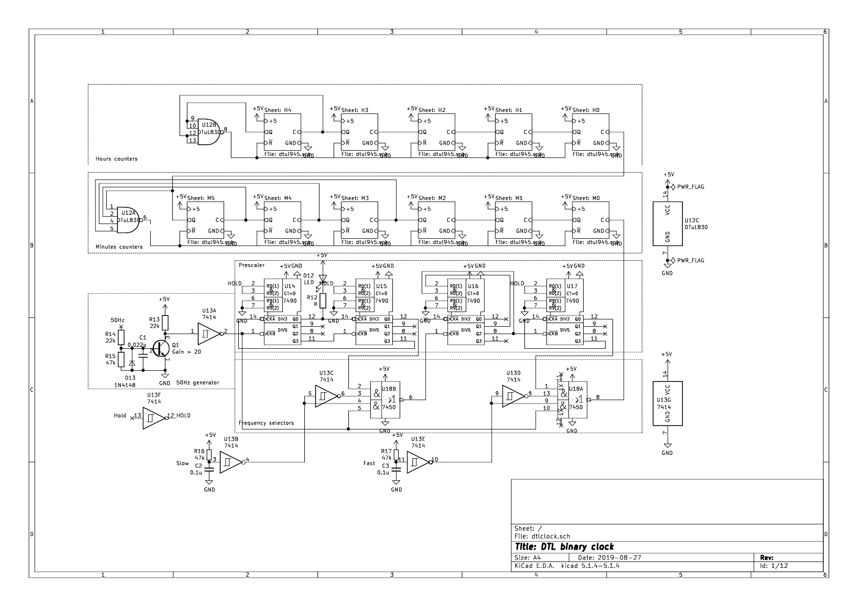
Time reference

I decided on 50 Hz mains so I have to prescale the input by 3000. I can do this with 4 TTL 7490 counters of which I have a lot. This means the design is not pure DTL but still retro. By adding a TTL 7450 dual AND-OR-INVERT gates as two-input selectors I can bypass part of the chain so that the hours and minutes can be set quickly. A TTL 7414 hex schmitt trigger for debouncing the switches and providing the inversion for the 7450 gates completes the line-up. One discrete transistor squares the sine wave from the transformer. For power I have to use an old-school step-down transformer, rectifier, and a 7805 voltage regulator chain, as a SMPS won't provide the 50 Hz reference. These power wall warts are getting rare. If I'll be making more mains frequency driven clocks I may have to put out a call to a local recycling group to snarf all the old power transformers left. 😀

Prescaler

The 7490 has separate divide by 5 and divide by 2 sections, so they can be used in two configurations. The first two 7490s divide by 5 twice then divide by 2 twice. This gets us a square wave rather than a 20% duty cycle wave. This is useful so that the pilot LED has a symmetric blink. If a calmer blink of 0.5 Hz instead of 1 Hz is desired, the LED can be driven from the divide by 2 output of U15 instead of U14. The penultimate 7490, U16, divides by 3, with outputs for 2^1 and 2^0 ANDed to reset to 0 after 2. The last stage U17 divides by 10 (5*2) and the output is a 1/60 Hz square wave, i.e. period of one minute.

Binary ripple counters

The master-slave DTµL flip flops feed the Q and Q' outputs back to the inputs crossed so that each clock pulse will invert the state, thus dividing by 2. The wiring looks hairy but each stage is wired identically. For the minutes the 32, 16, 8 and 4 flip flops go to a NAND gate to reset at 60. For the hours, the 16 and 8 flip flops go to a NAND gate to reset at 24.

I used sockets for the DTL chips in case I need to replace counters or gates. Or rather one counter I have only one spare. 😀

LEDs

The Q' outputs of the binary counters sink current so when Q' is 0 the LED lights up, i.e. when Q is 1. TTL/DTL outputs can sink much more current than they can source. One unit load is 1.6 mA. Most gates drive 10 ULs so up to 16 mA can be sunk.

I used greenred LEDs for the hours and redyellow LEDs for the minutes to make it easier to read. I also used rectangularsmaller LEDs for the high nybble. The pilot 1 Hz LED at the bottom uses an ambera blue LED. It also helps to orient the viewer when many LEDs are off.

Board...

Read more »

interboard.pdf

Interconnection between boards

Adobe Portable Document Format - 16.53 kB - 12/14/2020 at 03:28

Preview

dtlclock½.pdf

Schematic of one board

Adobe Portable Document Format - 125.12 kB - 12/14/2020 at 03:42

Preview

7490.ino

Arduino sketch to test 7490 decade counter

ino - 1.50 kB - 12/19/2020 at 12:49

Download

7450.ino

Arduino sketch to test 7450 dual AND-OR-INVERT gates

ino - 1.37 kB - 12/19/2020 at 12:49

Download

945.ino

Arduino sketch to test 945 flip-flop

ino - 1.30 kB - 12/17/2020 at 11:25

Download

View all 6 files

  • How TTL beat DTL

    Ken Yap11/17/2023 at 09:29 1 comment

    I stumbled upon a blog post by David Laws, written in 2015 for the Computer History Museum about how TTL overtook DTL. Fascinating read. TL;DR: Fairchild sticks with DTL, TI invests in TTL and becomes the leader. But the battle was not as clear cut as we now think in retrospect. Gordon Moore has a starring part.

  • Retro kludge

    Ken Yap09/10/2021 at 09:46 0 comments

    I thought I had finished with this clock and could let it go on blinking for the the rest of its/my life , but I discovered that it would sometimes glitch when going from 59 minutes to 0, the 8's LED would stay on. The clock would gain 8 minutes that hour.

    The problem was obviously due to my use of ripple counters. When the count reaches 60 = 2^5 + 2^4 + 2^3 + 2^2, the 4-input NAND gate should trigger and generate a negative going reset pulse. Unfortunately if the 8's flip-flop is slow resetting, the reset pulse would disappear before the reset is complete on that flip-flop.

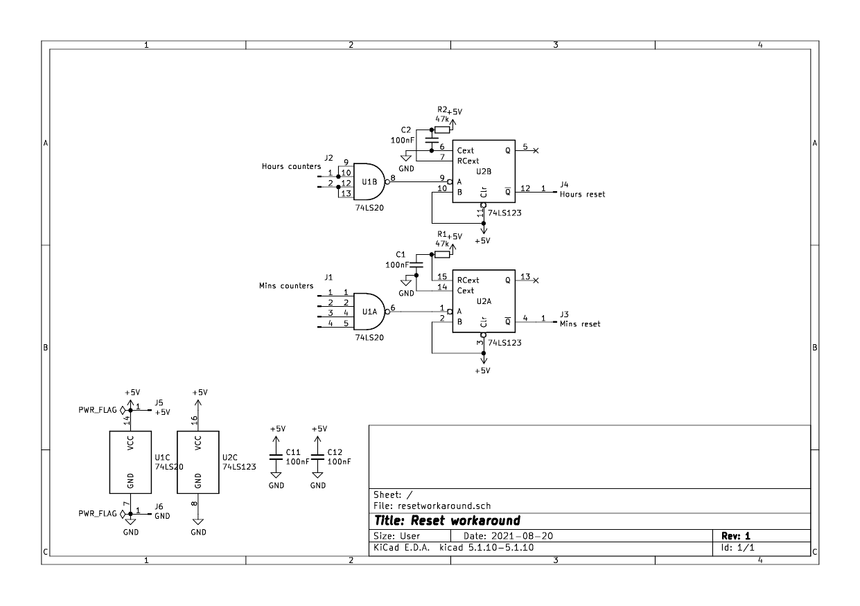
    The solution is to add a pulse stretcher. A 74LS123 dual retriggerable monostable is added after the outputs of the 74LS20 gates to ensure that we get a suitably long reset pulse. The R and C values chosen give a pulse width of 2 ms which should be enough. Incidentally it's the first time I've put a retriggerable monostable to use. I knew about these devices but never had the opportunity. I suppose you could use a 556 also.

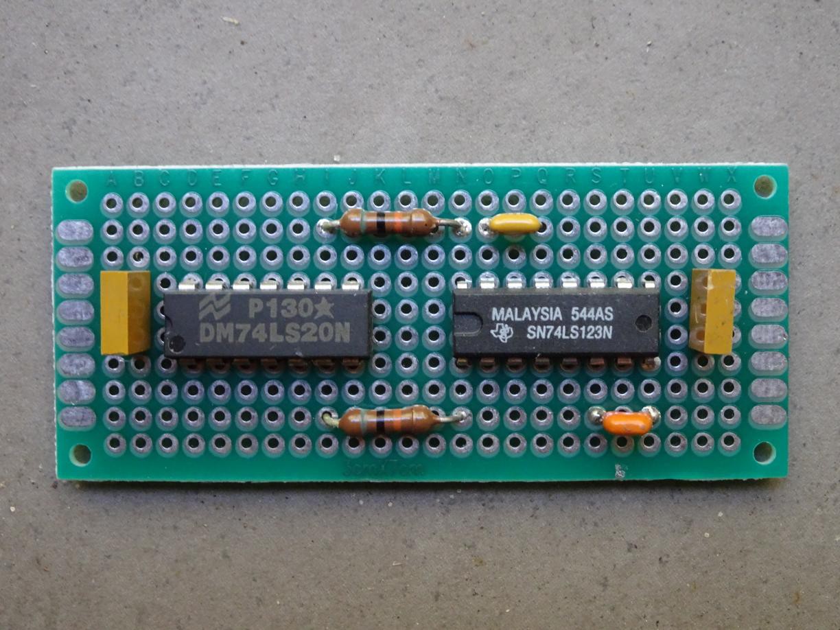
    The circuit was built on a piece of double sided PTH perfboard and connected to the 74LS20 pads by wire. It's a "solder-in" replacement, a NAND gates and pulse stretchers combination. This is the board before the fly leads were soldered. There are 10 in all, 5 for the minutes NAND, 3 for the hours NAND, and 2 for power.

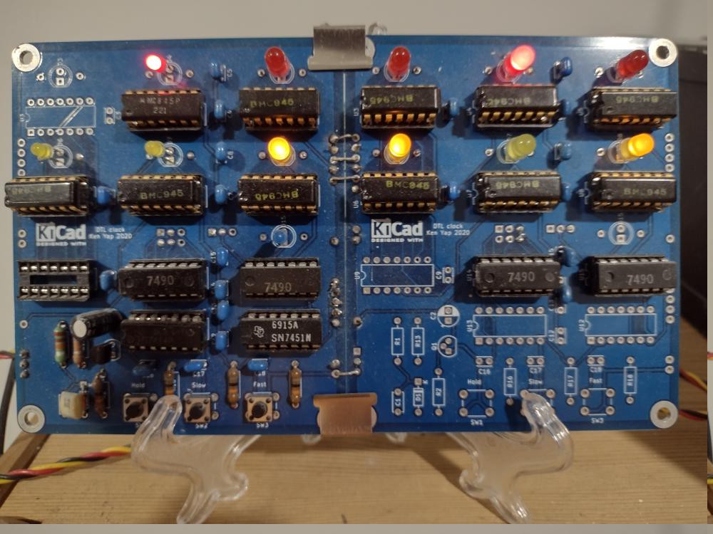
    Unfortunately an exposure sufficient to show PCB details washes out the LEDs, but the hours are red, the minutes yellow, and the seconds blinker blue.

    What time is it, Mr. DTLclock? 🕰️

  • Ancient DTL IC identified

    Ken Yap12/19/2020 at 13:48 0 comments

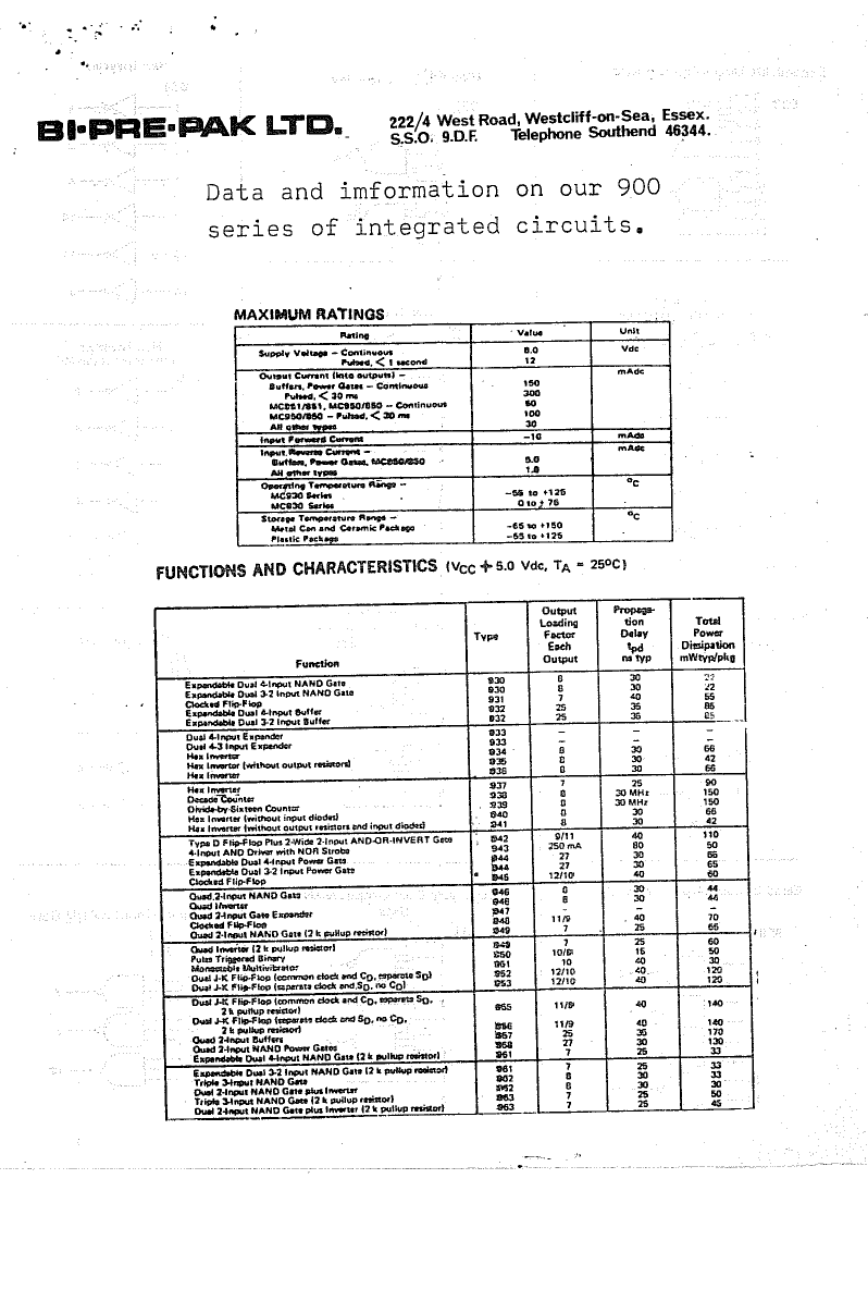
    Incidentally the DTL 945 flip-flops came from a grab bag that I bought as a schoolboy from Bi-Pre-Pak in the UK. There were several shops like this in the UK and the US that advertised in hobbyist and professional magazines. Sometimes the chips were surplus, sometimes seconds from the factories. Here is the first page of the leaflet that described what I got. The other pages have the pinouts.

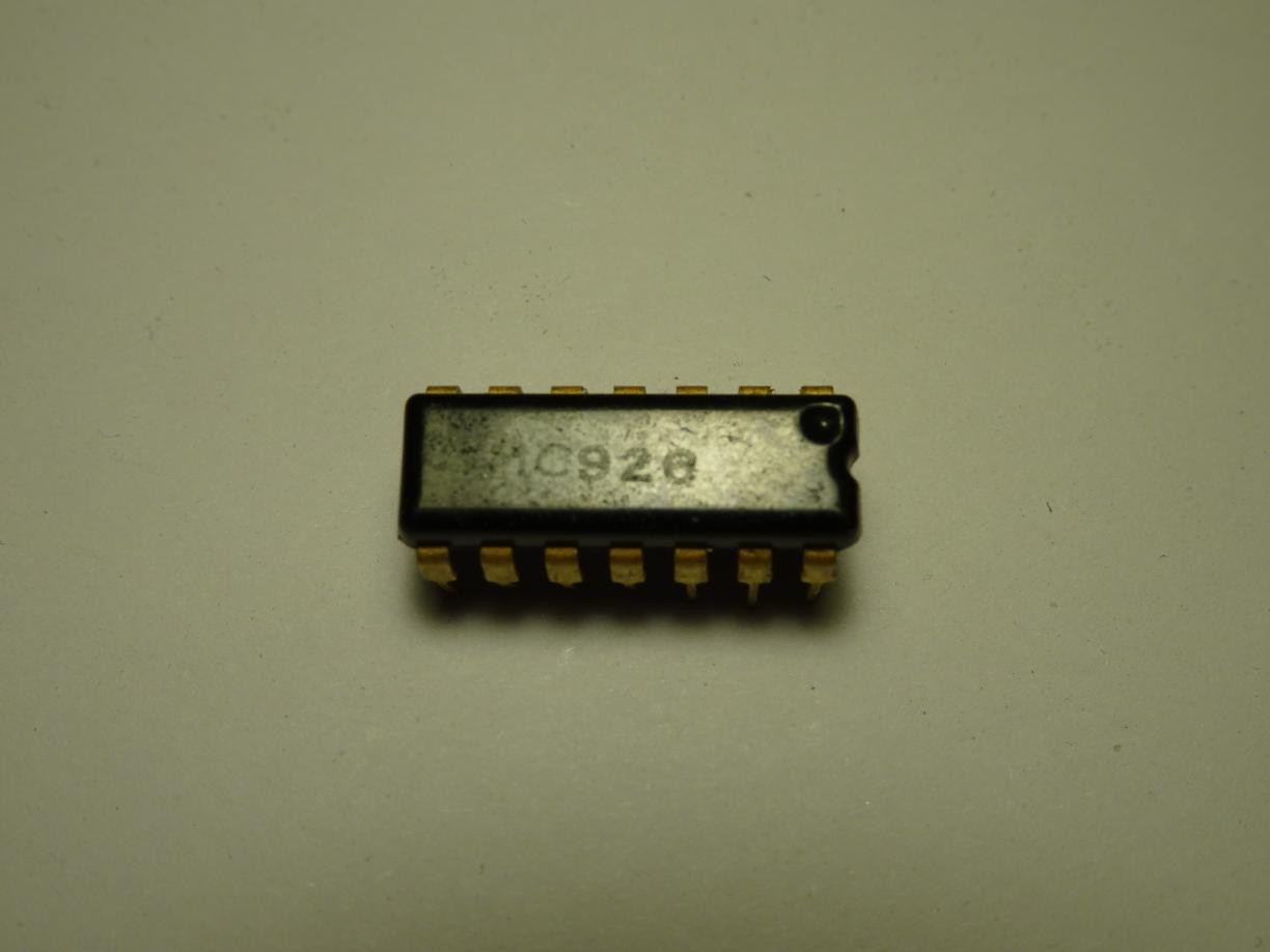
    There were also 8 chips that were marked BMC926 which were not described in the leaflet and I couldn't identify from any databooks. In fact the DTL series started at 930, the earlier ones being RTL, so that was puzzling. I have been in the dark for decades.

    Today I had a hunch that the last 2 digits were transposed, and the number should be 962, which designates a triple 3-input NAND gate. It has the same pinout as the 7410 so I selected that in my tester and lo and behold, they passed the test. An old mystery solved, even if it's of no practical consequence. Incidentally together with the 12 945 flip-flops, it means I must have bought a bag of 20 chips since I haven't used any of them until now.

    A search for Bi-Pre-Pak gets a few hits. One is of the managing director who retired in 1987 so the company would have been trading up till then at least. Another is of somebody who designed an audio power amplifier for them. So here's another retro-tale for the search engines.

  • Reversed transistor

    Ken Yap10/23/2019 at 23:13 0 comments

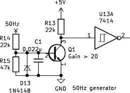
    In the DTL binary clock I run the 50 Hz mains frequency through a squarer consisting of a transistor and a schmitt inverter. Here is the circuit:

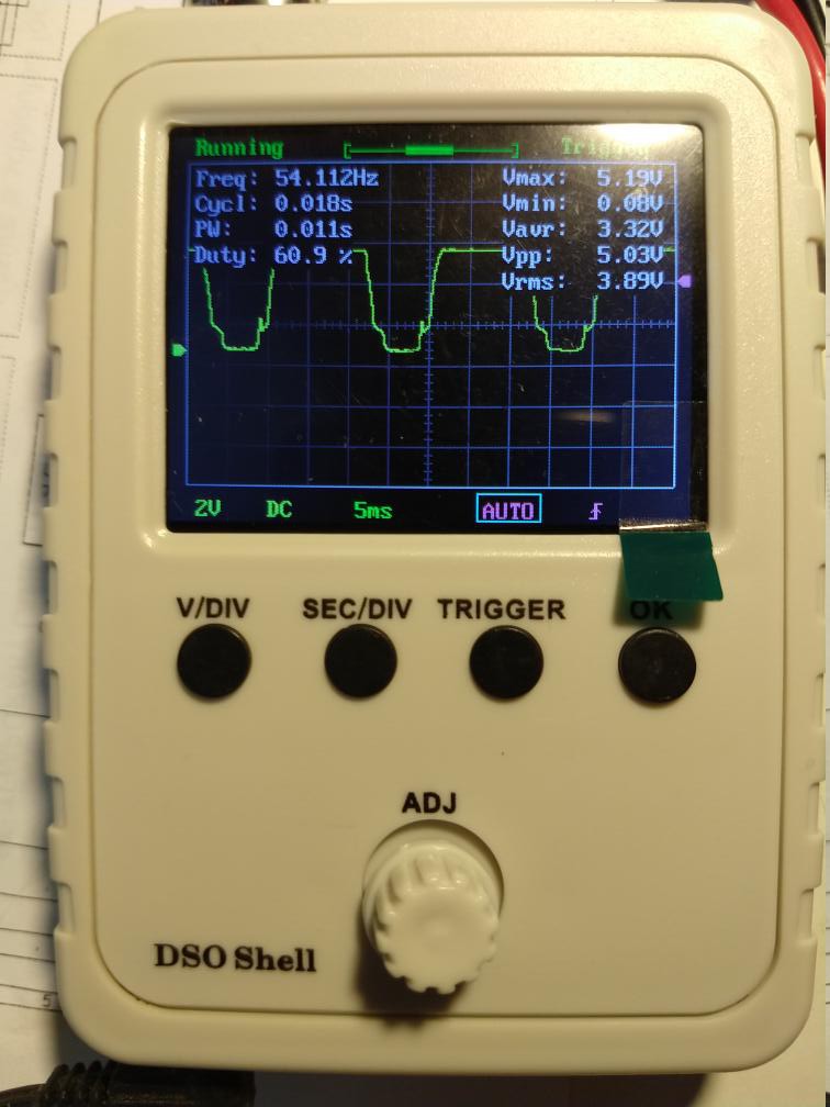
    There is a diode to limit the negative excursion of the base voltage. The first version worked fine. A second version using another set of components (the first set was set aside as working components for building a board) worked unreliably. I put a DSO on the collector of the transistor and saw this strange waveform.

    Finally it occurred to me to take the transistor off the breadboard and test it. It was then I realised my mistake. I had reached out and taken a transistor from the PNP bottle rather than the NPN bottle. But how did it even partly work?

    One of the questions a beginner encounters is if a NPN or PNP transistor has two junctions of the same type, how is the emitter different from the collector? Could we swap them around? Well, the difference lies in the doping of the emitter and collector, as this posting explains. And of course the B-E junction is forward biased and the B-C junction reverse biased in normal operation. So if we swap them around we would get a rather poor transistor with very low gain.

    Redrawing the circuit shows that I was running the PNP transistor in a emitter follower configuration. So what I took to be the collector was really was the emitter and its voltage was tracking the base voltage, so followed the input waveform.

    Putting in a NPN transistor made the circuit work as designed.

View all 4 project logs

Enjoy this project?

Share

Discussions

Yann Guidon / YGDES wrote 02/11/2020 at 00:09 point

Oh ! How did I miss this project ?

I'm a discrete clock wannabe DIYer and want to play with the various types of logic so any and all details are welcome !

  Are you sure? yes | no

Ken Yap wrote 02/11/2020 at 00:49 point

DTL is pretty much the same as TTL as far as design goes.

  Are you sure? yes | no

Ken Yap wrote 11/18/2019 at 02:48 point

Note that this simple frequency switching method will generate a spurious pulse when the button is pressed at the wrong phase of the clock input. You can read a paper on this referenced on this log page: https://hackaday.io/project/166922-spam-1-8-bit-cpu-with-a-tool-chain-twist/log/168393-clock-gating/discussion-132578

Unfortunately to fix would require making the control input synchronous with the clock which require more circuitry than I want. So I put the switch as far back in the counter chain as possible for the LEDs being advanced so that one extra pulse won't matter much.

  Are you sure? yes | no

kingcredie168 wrote 11/18/2019 at 01:47 point

Marke it,Thank you for explain this

  Are you sure? yes | no

trialexhill wrote 11/15/2019 at 04:39 point

Love it!

Can you explain a bit about the 7450? I'm looking at the datasheet, but not sure how you use it to select between different frequencies.

Thanks!

  Are you sure? yes | no

Ken Yap wrote 11/15/2019 at 04:49 point

The 7450 has dual AND OR invert gate groups, see the datasheet for the equivalent gate circuit. If one input each from the AND gates is driven in antiphase this has the effect of selecting one or the other of the AND inputs, effectively a silicon SPDT switch to choose between two frequencies. A two way multiplexer if you like.

If you are not concerned about TTL purity, you can do the same with a pair of CMOS transmission gates (e.g. CD4066) also driven in antiphase.

  Are you sure? yes | no

trialexhill wrote 11/17/2019 at 23:18 point

Cool so If I can try to use my limited electronics understanding to interpret your schematic...

The "Slow" side of U13B (pin 3) is normally high, so pin 4 is low. This is connected to pin 5 of U13C, so pin 6 is normally high. This is AND'd with the output from the second 7490. When that output goes high, the "output" (internal to the chip) is high. At the same time pin 4 of the 7450, an input to the bottom and gate, is low, so the output of that and gate is low. These go to the input of the OR, (high from top AND gate, low from bottom AND gate) so the output is HIGH, which is then inverted to be LOW. The opposite happens when the 7490 goes LOW (top and bottom and gates low, OR'd together gives low), giving a HIGH on the output of the 7450. The input and the output are out of phase, but that's OK, it's still oscillating. While all this is happening, these is a low on pin 4 of the 7450, so the output of that AND gate is always low.

When the Slow side of U13B is low, the input to the "top" AND gate on pin 3 of the 7450 is low, so nothing further happens on that and gate. On the "bottom" AND gate, pin 4 is now high, so when the 50Hz input also goes high, they AND together to be high, the OR gate has a low from the top gate and high from the bottom gate so outputs high, which is inverted to be low. Similarly as the top gate, when the 50Hz input goes low, low&low = low, low or low = low, inverted to high. Again out of phase, but oscillating.

Sorry I haven't used consistent phrasing there, but hopefully you get what I mean, and it helped me to type it out!

One more question about your design - where is the input? I was expecting to see physical switches where C2 and C3 are - how do you interact with your circuit?

Thanks again! 

  Are you sure? yes | no

Ken Yap wrote 11/17/2019 at 23:25 point

You can also map out a truth table.

There are push buttons. In TTL clock, which uses the same 2 input selection scheme, you can see them in the 3D rendering.

  Are you sure? yes | no

Similar Projects

Does this project spark your interest?

Become a member to follow this project and never miss any updates