Ken Yap
-
Stitching boards with paper clips
01/11/2025 at 07:42 • 0 comments![]()
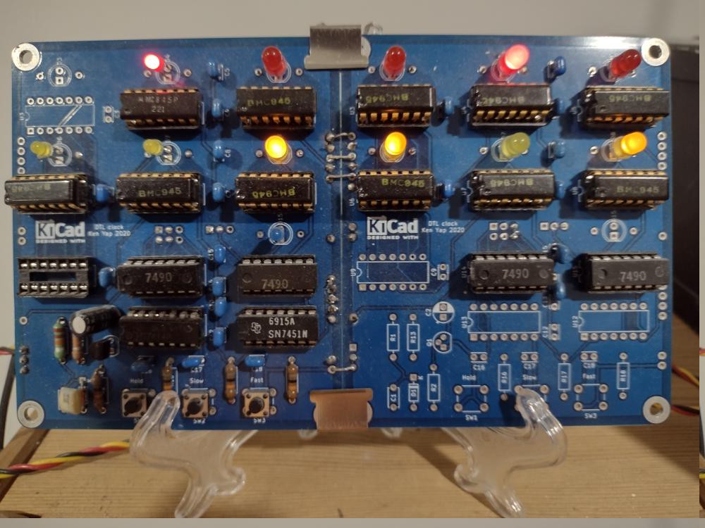
People who follow my display board projects know that I usually design them to be cascaded for more digits. They are connected in series using either Dupont pin sockets and pin headers, or just soldered jumpers as in the photo above. Neither is satisfactory as there is still flexure. I have considered using small aluminium straps and screws to hold the boards together stiffly using the corner holes. But I would have to look for aluminium strip of the right width and hacksaw small lengths off.
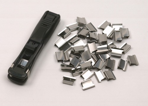
Today I tried another idea, using reusable paper clips that were designed to hold multiple sheets of a document together. They are attached to a corner of the document stack with a special tool. It's a solution between standard paper clips and fold back paper clips.
![]()
It works and I would also need to put some hot glue on the clips to prevent them from sliding off. However in future I will also need to design enough clearance so that the clip doesn't short PCB connections as the one on top in the picture almost does.
-
How TTL beat DTL
11/17/2023 at 09:29 • 1 commentI stumbled upon a blog post by David Laws, written in 2015 for the Computer History Museum about how TTL overtook DTL. Fascinating read. TL;DR: Fairchild sticks with DTL, TI invests in TTL and becomes the leader. But the battle was not as clear cut as we now think in retrospect. Gordon Moore has a starring part.
-
Retro kludge
09/10/2021 at 09:46 • 0 commentsI thought I had finished with this clock and could let it go on blinking for the the rest of its/my life , but I discovered that it would sometimes glitch when going from 59 minutes to 0, the 8's LED would stay on. The clock would gain 8 minutes that hour.
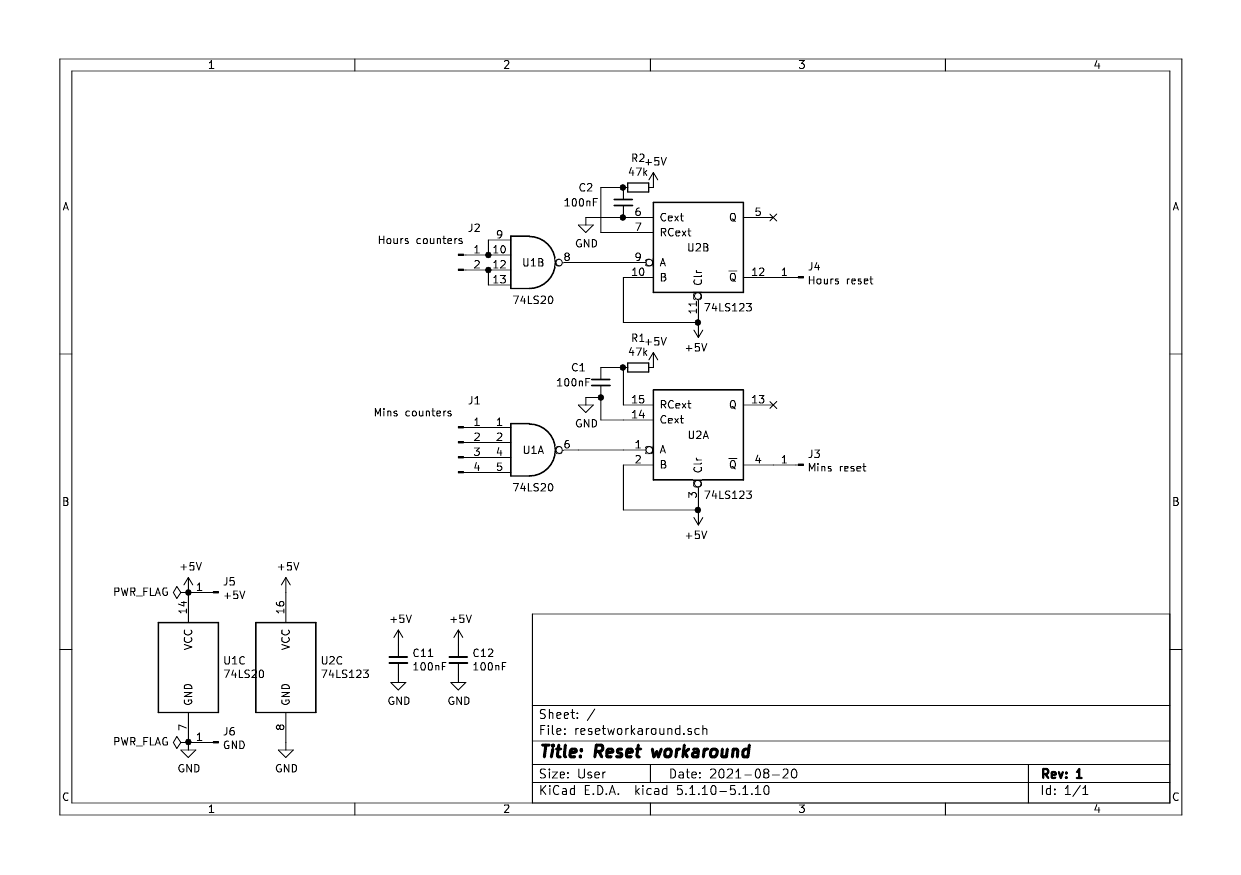
The problem was obviously due to my use of ripple counters. When the count reaches 60 = 2^5 + 2^4 + 2^3 + 2^2, the 4-input NAND gate should trigger and generate a negative going reset pulse. Unfortunately if the 8's flip-flop is slow resetting, the reset pulse would disappear before the reset is complete on that flip-flop.
The solution is to add a pulse stretcher. A 74LS123 dual retriggerable monostable is added after the outputs of the 74LS20 gates to ensure that we get a suitably long reset pulse. The R and C values chosen give a pulse width of 2 ms which should be enough. Incidentally it's the first time I've put a retriggerable monostable to use. I knew about these devices but never had the opportunity. I suppose you could use a 556 also.
![]()
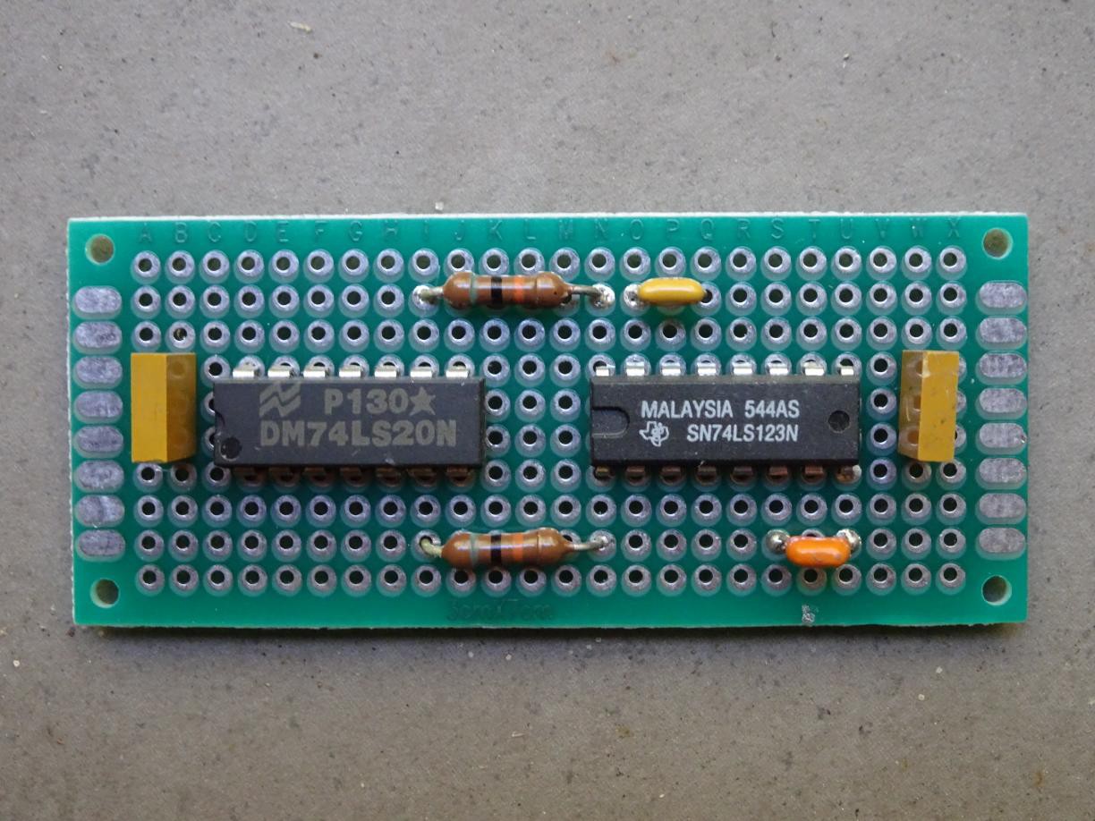
The circuit was built on a piece of double sided PTH perfboard and connected to the 74LS20 pads by wire. It's a "solder-in" replacement, a NAND gates and pulse stretchers combination. This is the board before the fly leads were soldered. There are 10 in all, 5 for the minutes NAND, 3 for the hours NAND, and 2 for power.
![]()
Unfortunately an exposure sufficient to show PCB details washes out the LEDs, but the hours are red, the minutes yellow, and the seconds blinker blue.
![]()
What time is it, Mr. DTLclock? 🕰️
-
Ancient DTL IC identified
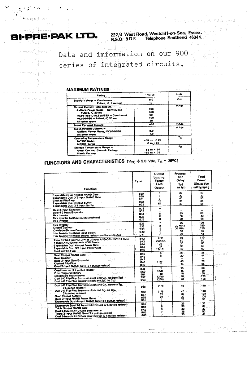
12/19/2020 at 13:48 • 0 commentsIncidentally the DTL 945 flip-flops came from a grab bag that I bought as a schoolboy from Bi-Pre-Pak in the UK. There were several shops like this in the UK and the US that advertised in hobbyist and professional magazines. Sometimes the chips were surplus, sometimes seconds from the factories. Here is the first page of the leaflet that described what I got. The other pages have the pinouts.
![]()
There were also 8 chips that were marked BMC926 which were not described in the leaflet and I couldn't identify from any databooks. In fact the DTL series started at 930, the earlier ones being RTL, so that was puzzling. I have been in the dark for decades.
![]()
Today I had a hunch that the last 2 digits were transposed, and the number should be 962, which designates a triple 3-input NAND gate. It has the same pinout as the 7410 so I selected that in my tester and lo and behold, they passed the test. An old mystery solved, even if it's of no practical consequence. Incidentally together with the 12 945 flip-flops, it means I must have bought a bag of 20 chips since I haven't used any of them until now.
A search for Bi-Pre-Pak gets a few hits. One is of the managing director who retired in 1987 so the company would have been trading up till then at least. Another is of somebody who designed an audio power amplifier for them. So here's another retro-tale for the search engines.
-
Reversed transistor
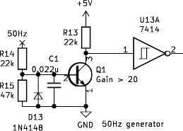
10/23/2019 at 23:13 • 0 commentsIn the DTL binary clock I run the 50 Hz mains frequency through a squarer consisting of a transistor and a schmitt inverter. Here is the circuit:
![]()
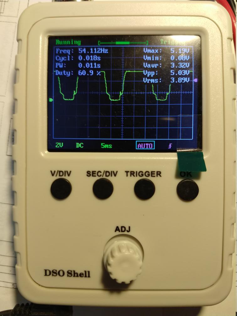
There is a diode to limit the negative excursion of the base voltage. The first version worked fine. A second version using another set of components (the first set was set aside as working components for building a board) worked unreliably. I put a DSO on the collector of the transistor and saw this strange waveform.
![]()
Finally it occurred to me to take the transistor off the breadboard and test it. It was then I realised my mistake. I had reached out and taken a transistor from the PNP bottle rather than the NPN bottle. But how did it even partly work?
One of the questions a beginner encounters is if a NPN or PNP transistor has two junctions of the same type, how is the emitter different from the collector? Could we swap them around? Well, the difference lies in the doping of the emitter and collector, as this posting explains. And of course the B-E junction is forward biased and the B-C junction reverse biased in normal operation. So if we swap them around we would get a rather poor transistor with very low gain.
Redrawing the circuit shows that I was running the PNP transistor in a emitter follower configuration. So what I took to be the collector was really was the emitter and its voltage was tracking the base voltage, so followed the input waveform.
Putting in a NPN transistor made the circuit work as designed.