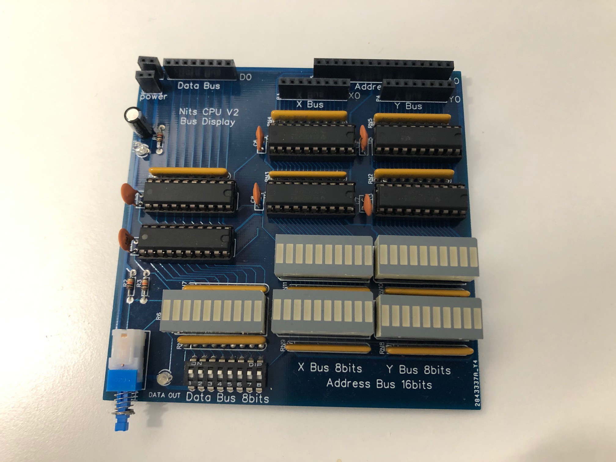
The first PCB I wanted to create was dedicated to displaying all the Buses and provide the capability to publish a value to the Data Bus. A helpfull debugging tool.
This module provides the following:
- Display the 8-bit X Bus
- Display the 8-bit Y Bus
- Display the 16-bit Address Bus
- Display the 8-bit Data bus
- Publish a manual value, set using dip switches to the 8-bit Data bus
In order to minimize impact on the buses when plugging the module all the LEDs are driven by a 74LS245 bus driver.

The PCB is dual sided, ordered from a well known provider.
The switch enables the publishing of the Data bus value. No switch debouncing is needed on this test board. It works perfectly.
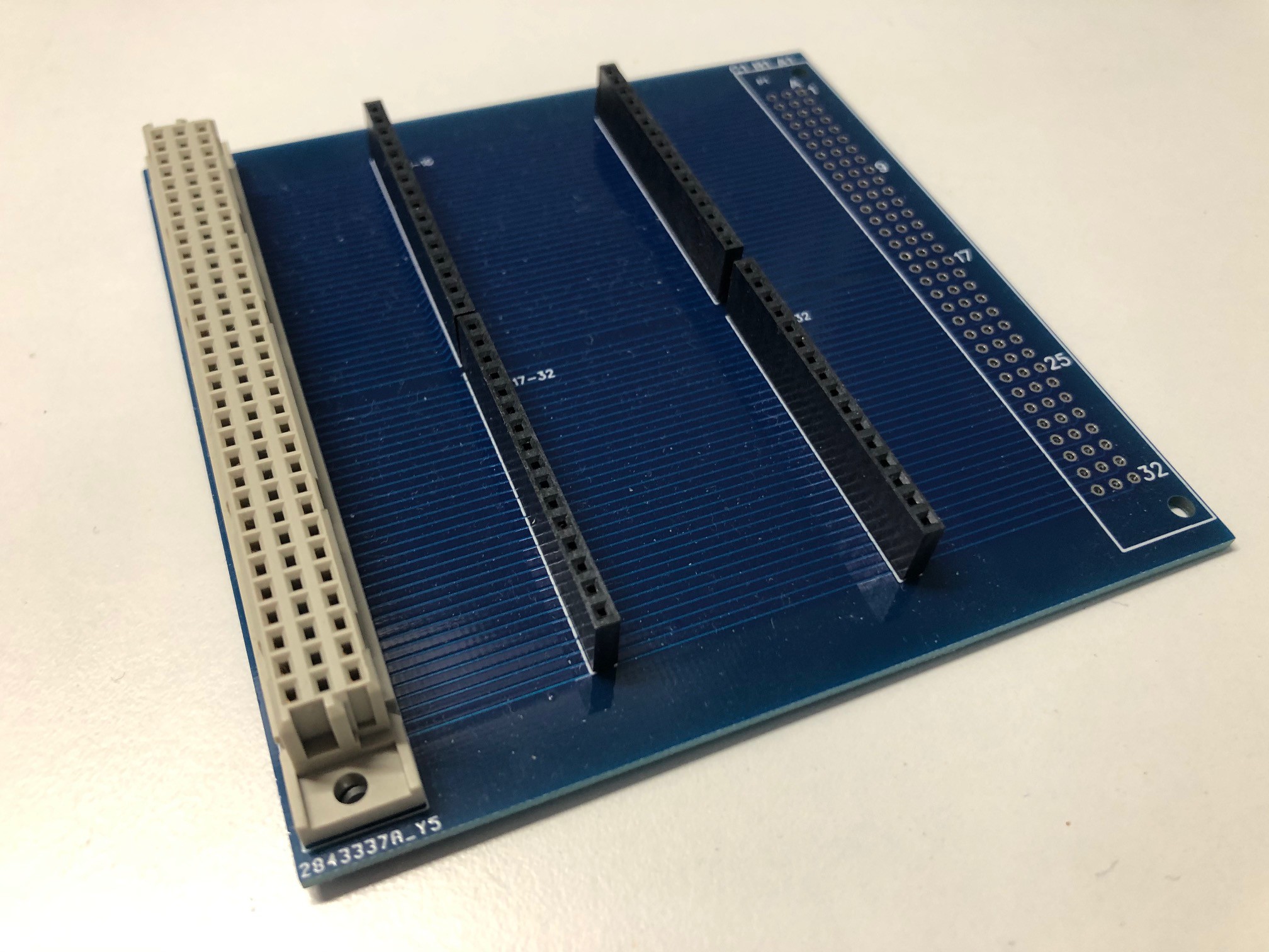
The second PCB, also for test purposes is a simple 41612 64 pin connector facilitator. It enables easy access to any pin of the connector to use a dupont-cable.

I built 2 of thoses, on for the female 41612 connector (seen here), one for the male version (just solder a male connector on the right side of the PCB instead) in order to also test the backplane.
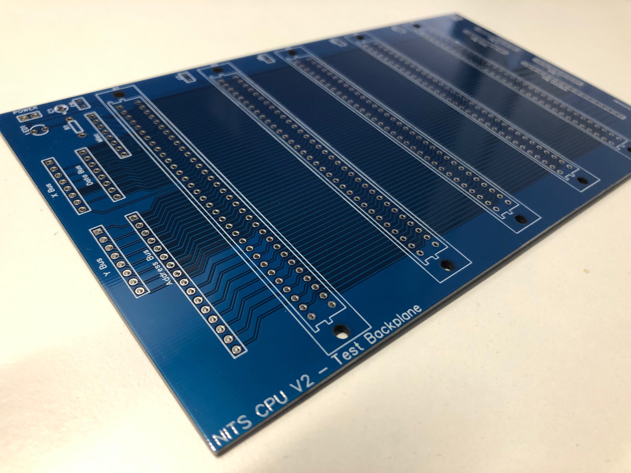
Here is a preview of the test backplane (connectors not installed). It provide 5 41612 connectors, power supply, decoupling caps, and direct access to some buses (to be used by the bus display above).

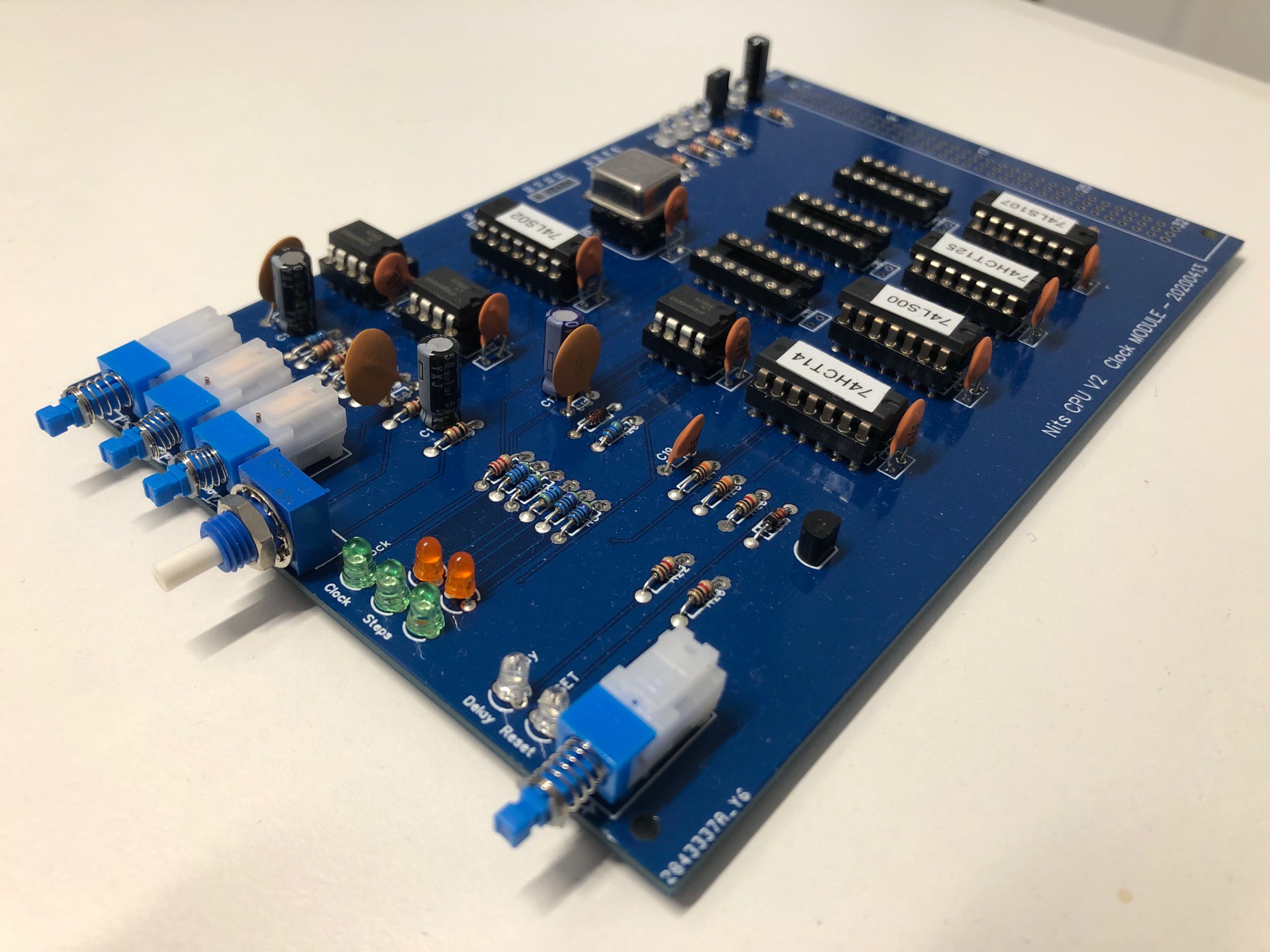
Finally, my big error in design, I built a PCB for the final version of the clock module, quite a complex PCB for my level of expertise and I messed up one chip (used a NOR instead of an OR gate and the pinouts are not compatible). So this is the partially built version. I stopped when I found the error.

It was supposed to have an 41612 connector, get power from the baclplane and provide reset and clock to the backplane. I will therefore need to design a second version.
Until the redesign, I will hack this one to make sur the updated design fixes the errors.
 Ced
Ced
Discussions
Become a Hackaday.io Member
Create an account to leave a comment. Already have an account? Log In.
Bus-Display board: I did something similar - https://hackaday.io/project/170938/log/178836-more-corrections - not near as fancy as yours, and I just used simple '04s. As a 74' chip sinks current much better than source, the LEDs are between 5V and the inverter, which pulls to ground when the line is high.
Are you sure? yes | no
OR-NOR ooops: Desolder the socket (on the pic there is one), then solder short wires into the holes. You cross the wires pin 1/3, 4/6, 8/10 and 11/13. The others you let go straight up. Now you can solder a socket on these wires, and put the right chip in socket. It wont be pretty, but you can test the rest of the board. You're not limited to one error per board :-)
Are you sure? yes | no
Yeah I guess I'm not the first one with this issue. Thanks for the tip and indeed I was planning to use a breadboard to make sure there are no more errors before creating a new PCB.
But actually that is why this is fun. Make mistakes and learn :)
Are you sure? yes | no