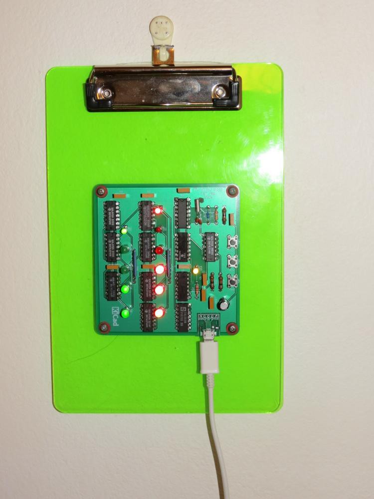
After my DTL binary clock I decided to make a TTL binary clock along the same principles. I have enough old TTL chips to make a few to give to geek friends. I can tell them that this clock can outlast me so it will be a memento. 😀
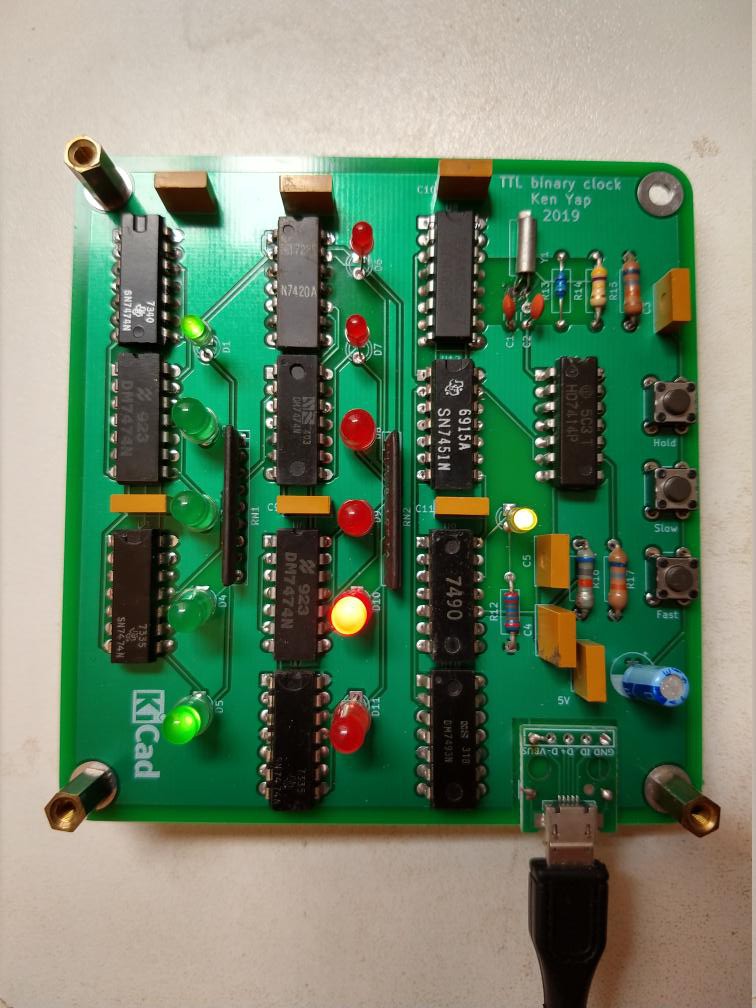
By using dual D flip-flop 7474 packages I can fit it all on a 100x100 mm board for cheap PCB fabrication.
Old-school transformer wall-warts are in short supply though. I have harvested a lot of 5V phone chargers from the local e-waste bin but these are modern switching mode power supplies. This is good as they are lighter and more efficient but I have to find another timing source.
A trawl through my junk box revealed lots of 32768 Hz crystals extracted from PC real time clock circuitry. I found that the CD4060BC oscillator and 14 stage divider is still available cheap. So I have designed a clock generator around this. The final output is 2 Hz, so a 7490 and a 7493 are used to divide by 120 to get a 1 minute period signal. The usual chain of flip flops follows: A 6 stage counter divides by 60 to count minutes, resetting at 60. A 5 stage counter divides by 24 to count hours, resetting at 24.
There were some issues with getting the crystal to oscillate on the breadboard, documented here. It should work on the PCB, where I have ensured the required electrical isolation.
One drawback is that the long term accuracy is not as good as the mains. If we assume a worst case 20 ppm error in the crystal, this means that in a year (about 30 million seconds) it will deviate by up to 600 seconds (10 minutes) from the true time. On the average it should be less, but this means that the clock should be adjusted every month or two.
LEDs are driven directly from the Q' output of the flip flops. Modern LEDs are so efficient that I can run them at about 2-3 mA well within the current sinking capability of TTL logic. I used 1 kΩ resistor networks to save space and reduce soldering.
As with the DTL clock, faster clock frequencies are routed by switches to fast set the hours and minutes.
5V power input is via a micro USB connector, taking advantage of readily available USB A to micro USB cables.
 Ken Yap

 Dave Gönner
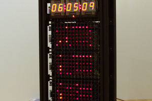
 Ted Yapo
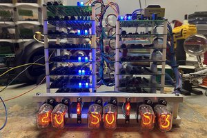
 Sean B
With all those decoupling caps and resistor networks it has a proper TTL look to it, doesn't it? What kills me is that I threw away probably everything needed to make something like this when I moved three years ago. Chips with date codes from the 1970s - I just pitched them. Shameful...