Ken Yap
-
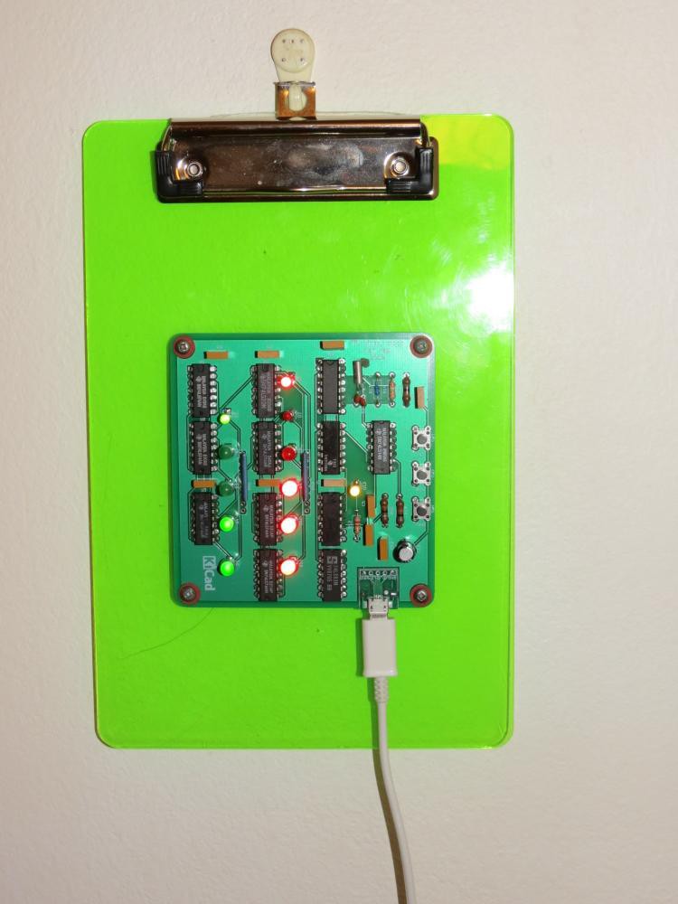
Mounted and ready to gift
12/17/2019 at 08:53 • 0 commentsI mounted a couple on A5 plastic clipboards each a couple of dollars from the local office supply store. They have a tab to hang on a wall hook.

One recipient elected to mount the board on his gift lower down to have space above to clip notes. He joked that he could now write notes like: Fed the cat at 13:27 which is the time shown above in hex. -
Working correctly now
11/18/2019 at 10:31 • 0 commentsIn the last log I complained how the 1 Hz square wave was glitchy and making the clock run fast. I thought about it and realised I had not checked the fan out of the CD4060 2 Hz output feeding the 7450 multiplexer. Turns out that the CD4060 is only rated for a 2 LS gate fan out. Unfortunately the 7450 I used is standard TTL, so effectively 4 LS loads or 1.6 mA. This was causing logic low to be too high and making the gate levels marginal.
I don't want to rework this board, at least not now, so I added a 4k7 pull down resistor at that gate (pin 1 of the 7450) to assist with logic 0. Now the signal is stable. In the remaining boards I'll be using a 74LS50 which will be fine. I'm running out of old standard TTL chips anyway.
I would have caught this issue at the breadboarding stage, except that I didn't test the combination of the CMOS output with TTL input due to the issue of the 32.768 kHz crystal not oscillating on a breadboard which I have previously blogged.
Lessons for me: When mixing logic families, check the logic levels and loading limits, and the breadboard should test as much of the real operating circumstances as possible.
Declaring this project completed. I may write a page or two when I find a good presentation for making gifts. I'm considering mounting the board in a wooden photo frame that sits on a desktop.
-
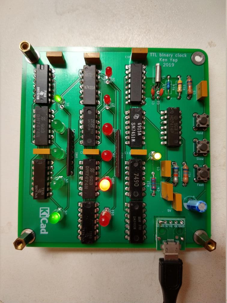
Assembled PCBs
11/14/2019 at 22:20 • 0 commentsI got the PCBs a while back from a recent Elecrow offer. I ordered 5 PCBs and was delivered 7. Hope I have enough old TTL chips to populate them all. The power is supplied from a 5V phone charger via this micro USB socket.
I populated a couple of boards. I soldered LEDs to one and powered it on. The copper pillars are to hold the board a certain distance above the table while I soldered the LEDs in so that they would all be the same height above the board.
Unfortunately while the counters work correctly, the 1 Hz LED sometimes blinks erratically, with spurious pulses, which cause the counters to speed up. Have to bring out the DSO to see where the extra pulses are coming from.
I also noted that I have to use a decent micro USB cable, the voltage drop across cheap ones is significant.
Edit: A few minutes later: Now the clock has settled and the 1 Hz LED is blinking at a steady rate. I hate it when circuits "fix themselves" like that. I'll leave it running to see if the glitch has gone for good. Probably not. 😿