-
1Stage 1 - 1Hz Timebase
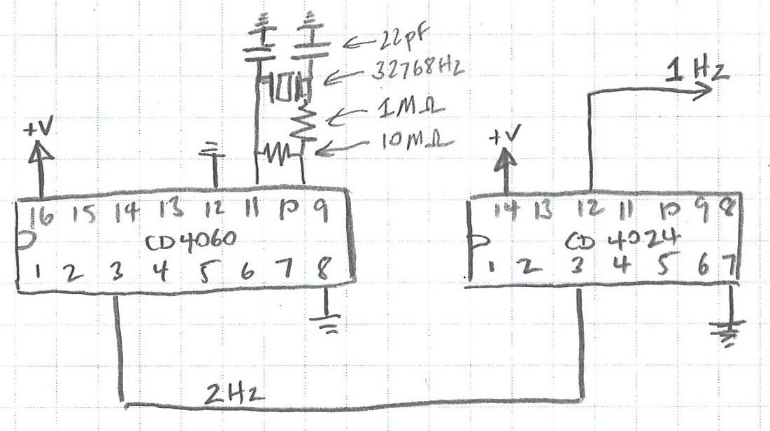
This section creates a 1Hz pulse output.
The intent of the clock is to just display minutes only. Although I'm not actually displaying or keeping track of seconds, there is no such think as a 1/60Hz (0.166666Hz) crystal. It would be possible to create a 1/60Hz frequency output using a 555 timer and carefully chosen capacitors and resistors, but getting an accuracy acceptable for a clock would be impossible. It is better to go with a crystal and divide the frequency down.
A 32768Hz crystal is connected to the inputs of a CD4060 IC. The IC divides the frequency by two on each successive input. For example the first output is Q4 (pin 7), so for a 32768Hz input, the output is 32768/(2^4)=2048Hz.
Unfortunately the last output is Q14, which gives 32768 / (2^14) = 2 Hz. Although I'm not actually displaying seconds on my clock, it would be nice to have a 1Hz frequency available, even just for ease of thinking about future diiding a once per second pulse to a once per minute pulse.
The 2Hz signal from the CD4060 is then passed to the input of a CD4024 IC. This IC again divides the frequency by 2 at each stage, giving a 1Hz signal on output Q1 (pin 12).
Although these chips have similar functions, and it'd be nice to use just one type of IC, the CD4060 generates the output based on an external crystal/resonator, whereas the CD4024 needs an existing clock signal.
I've used these two ICs to create a 1Hz signal for a previous task. While building that project I found that it was unreliable on a breadboard, but worked much more reliably when soldered to a prototyping board. For this project I will build this part of the circuit on the final board initially, as I'm confident in assembling it correctly. I can use the output to drive other new sections built on a breadboard.
The values for the resistor and capacitor are probably not critical, but are what I've previously used. I'm not sure where I got them from originally, but they are similar to many other examples online. Pin 12 on the CD4060 is a reset pin, and should be grounded during normal use.
BOM for this stage:
- 1 x CD4060
- 1 x CD4024
- 1 x 32768Hz crystal
- 2 x 22pF capacitors
- 1 x 1Mohm resistor
- 1 x 10Mohm resistor
- 1 x 16 pin IC socket
- 1 x 14 pin IC socket
![]()
-
2Stage 2 - One pulse per minute
Stage 1 results in a 1Hz (i.e. once per second) signal. This clock will display minutes, so the signal needs to be divided by 60 to get a 1/60Hz (once every sixty seconds or once per minute) signal.
The first stage took advantage of frequency dividers that used binary powers to quickly reduce the frequency. Given this stage divides by 60, which is not a power of 2, the dividers need to use decade counters. A common part to do this is the 74LS90.
The 74LS90 internally has two stages, a divide by two and a divide by five. The output of the first stage can be fed into the input of the second stage, to give a maximum of divide by 10. The outputs can be cleverly combined with the reset pins to give an output of any number between two and ten.
To divide by 60, the two 74LS90 ICs are used. The first divides the input of the first stage by 10, giving an output of 1/10Hz. This is passed to the second 74LS90, which divides the signal by six to give the desired output of 1/60Hz or one per minute.
In regards to the reset pin configuration, I don't have a great understanding of how to calculate which inputs and outputs are connected. To work it out I used the datasheet and this excellent site.
BOM for this stage:
- 2 x 74LS90
- 2 x 14 pin IC socket
![]()
-
3Stage 3 - Display Minutes
This stage displays the minutes on 60 LEDs arranged as a bar graph.
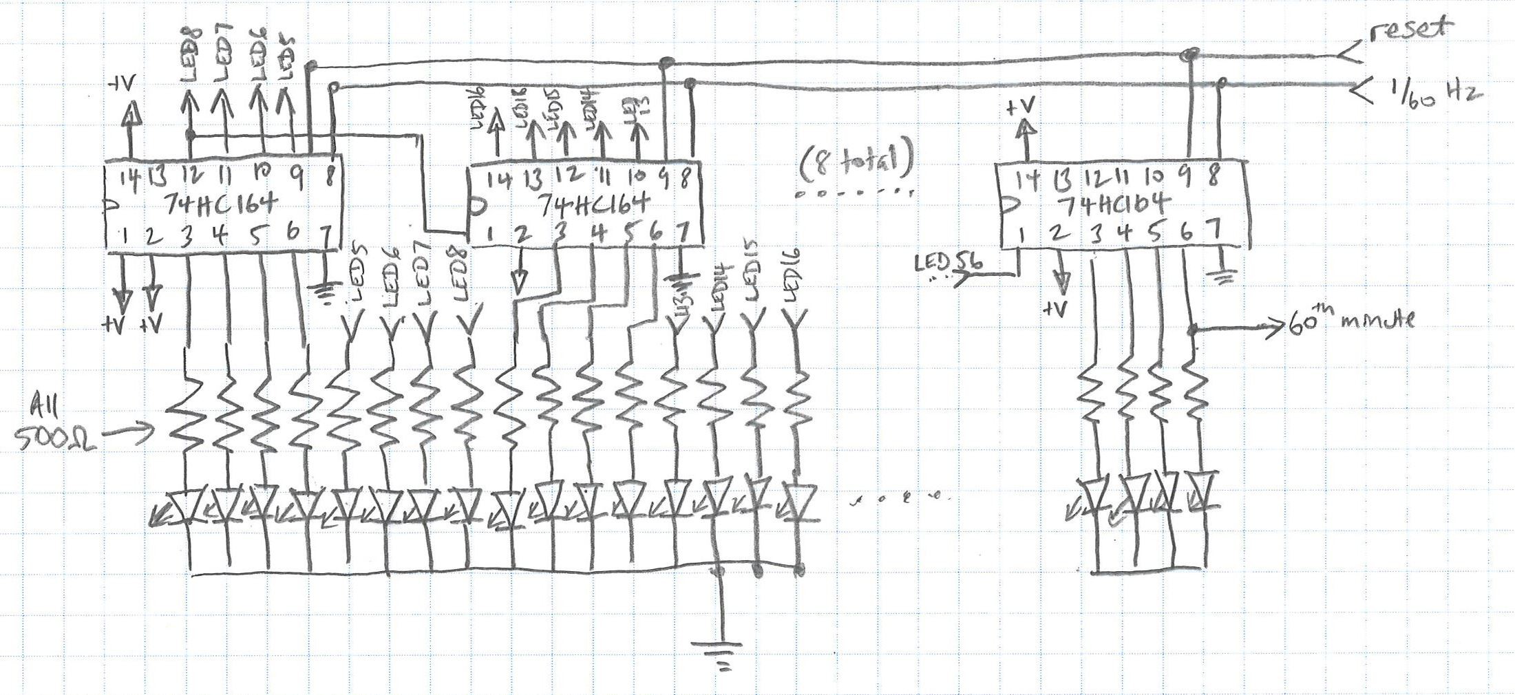
74HC164 serial-in, parallel-out shift registers are used. The shift register looks at it's inputs, and at every clock input, shifts all of the current values one over, looks at the current value of the input, and adds that value to the bottom of the pile. For this application, we start the hour with all low values, and every minute add one high value to the pile. So the input to the first 74HC164 is always high (the 74HC164 has two input pins [1 and 2] which are OR'd together, so we need both to be high). The 1 pulse per minute is applied to the clock pin, pin 8.
When the clock is turned on, all values in the shift register are low, so all the LEDs are turned off. After one minute the clock pin changes from low to high. The 74HC164 reads the input pins as high, so changes the first output pin to high, and the first LED turns on. After one minute, the clock pin again changes from low to high, the 74HC164 moves the high value from the last minute to the second output, and again reads the input pins as high, making the first output high again. Now the first two LEDs are turned on.
The 74HC164 has only eight outputs. The 74HC164 can be "daisy chained" - the last output of the one can become the input of the next. By doing this eight times, there are enough total outputs to control 60 LEDs.
All of the clock pins of the 74HC164s are connected, so that they all change simultaneously.
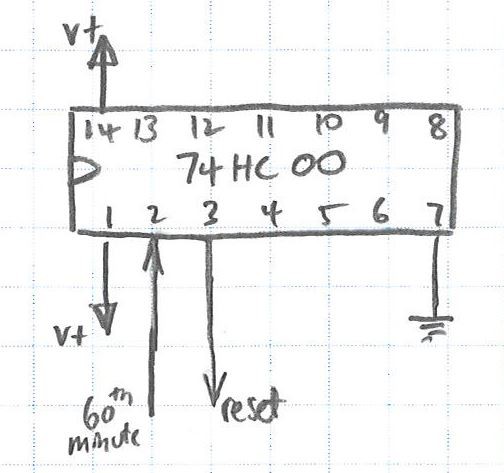
After one hour, all of the LEDs need to be turned off again to start counting a new hour. This is done but resetting the 74HC164s. The reset pin is pin 9, and it is reset when the pin is low. We have a "signal" when the hour occurs, i.e. the 60th output of the chain of 74HC164s, but this is a high signal. A NAND gate in a 74HC00 is used to invert the signal. The NAND gate takes two inputs, and outputs high if either of the inputs are low (and conversely a low when both inputs are high). One of the inputs is permanently held high, the other is connected to the 60th output. During the first 59 minutes, the 60th output is low, so the NAND gate output is high, and the 74HC164s operate as normal. When the 60th output goes high, both NAND gate inputs are high, so the NAND gate output goes low. The output is connected to all of the reset pins of the 74HC164s, so when the NAND gate goes low, all of the 74HC164s reset, and the whole process starts again.
BOM for this stage:
- 8 x 74HC164
- 1 x 74HC00
- 9 x 14 pin IC socket
- 6 x 10 LED bar graph displays
- 6 x 20 pin IC sockets
![]()
![]()
-
4Stage 4 - Set The Time
It would be frustrating to have no way to set the time - you'd have to turn on the clock at the top of the hour.
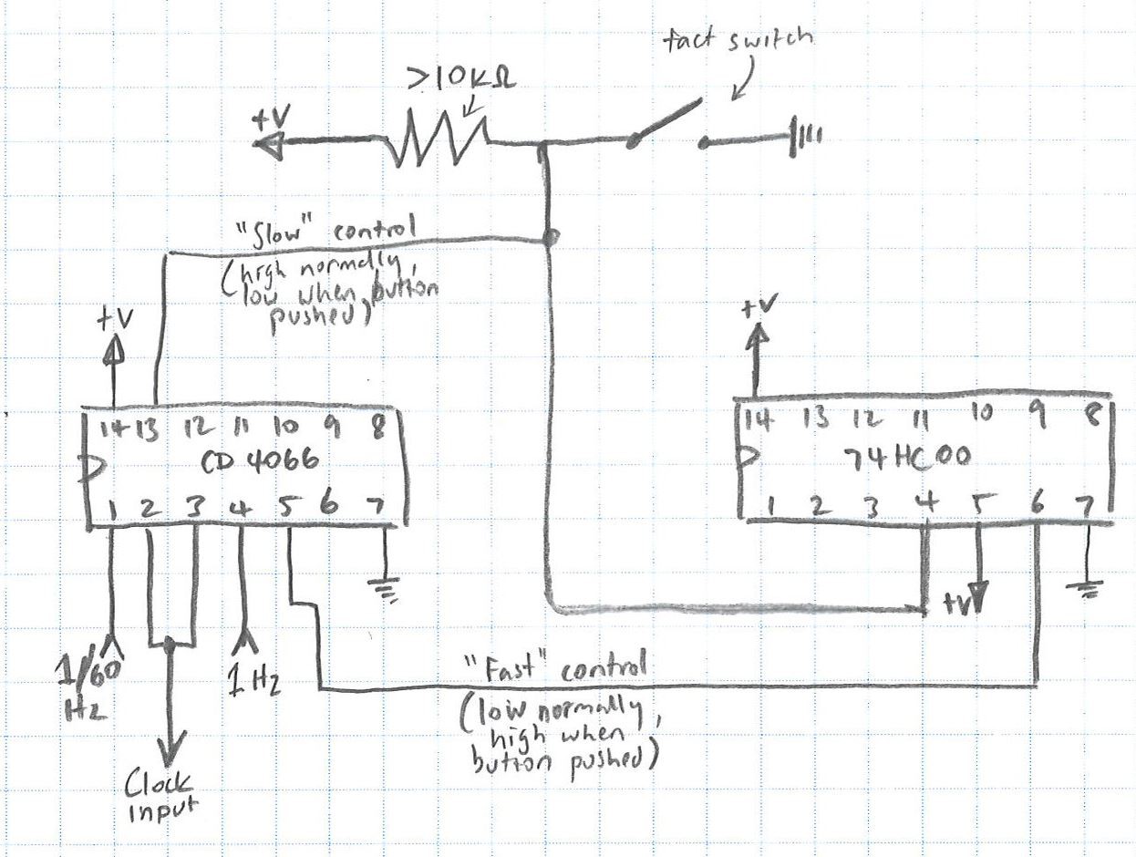
The time is set by disconnecting the one pulse per minute input to the '164's, and instead using the one per second pulse. Switching between the signals is done using a tact switch, and a combination of one of the 74HC00 NAND gates, and a CD4066 "electronic switch".
Both signals are fed into into the 4066. The control pin for the one per second pulse is connected to a "voltage divider" with a switch on the low side. In the normal state, the button is not pushed, so the control pin for the one per second pulse is high, and the 4066 passes through the one per second pulse. The same control signal is also fed to the 74HC00 NAND. The other pin on the same NAND gate is connected to 5V. So in the normal state with no button push, the output of the NAND gate is low. This is connected to the control pin of the one per second pulse of the 4066. Because it's low, the 4066 gate blocks that signal.
When the button is pushed, the control pin of the one per second is now low, and the control pin for the one per minute is high. The 4066 then lets through the one per second signal, and blocks the one per minute signal.
BOM for this stage:
- 1 x CD4066
- 1 x 14 pin IC socket
- 1 x pull up resistor
- 1 x tact switch
![]()
-
5Stage 5 - Power
I'm going to use a cheap and cheerful micro-USB breakout for power. It almost perfectly fits the prototyping board I'm using, it just needs a few traces cut and a jumper between one pin and my positive voltage rail.
TTL/CMOS Linear LED Clock
A TTL/CMOS based clock that displays the time along a 60 LED bargraph.


Discussions
Become a Hackaday.io Member
Create an account to leave a comment. Already have an account? Log In.