0%
0%
Hacking a Cossor (Raytheon) Husky Printer
Printers from military surplus with absolutely no documentation and an obscure interface connector... sounds like a good hacking project.
 Andy Preston
Become a Hackaday.io member
Already have an account? Log in.
Just one more thing
To make the experience fit your profile, pick a username and tell us what interests you.
Pick an awesome username
hackaday.io/
Your profile's URL: hackaday.io/username. Max 25 alphanumeric characters.
Pick a few interests
Projects that share your interests
People that share your interests
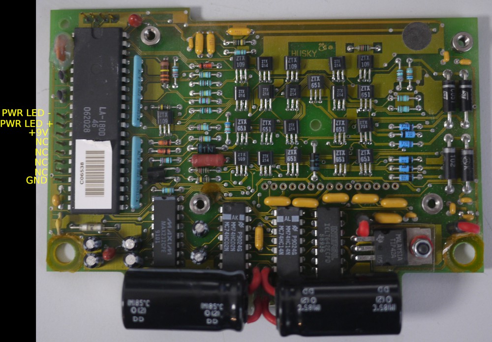
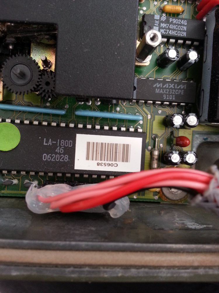
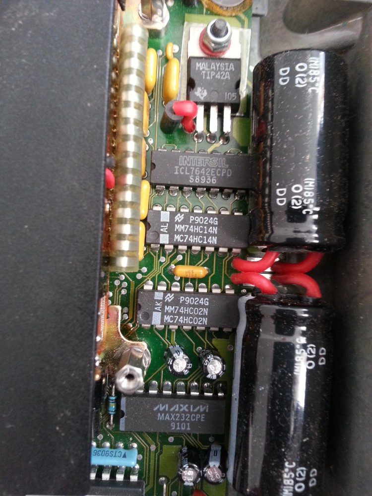


Looks like the interface connector is made by Glenair. Those connectors are similar in cost and reliability to the infamous Amphenol ones used in most other military equipment. They are not unobtanium, but they are not cheap either. I agree with you about the large IC; Probably some kind of 8051 part, custom ROM masked for this application and house numbered. If you really want to print something with it, you may find it easier to reverse engineer and duplicate the drive circuitry for the print head and associated mechanism, and using a microcontroller of your choice to handle the interfacing. There may be some kind of key exchange, or unlock that has to happen to enable the device. I could also be totally wrong, and you may find it just responds to serial data on the four-pin header using some kind of simple serial protocol like some older receipt printers. There does not seem to be any sort of voltage regulation, so I bet you supply it with 5V directly, via the four pin interface connector. I notice a cable coming off to the side of the Large IC, what did this hook to?