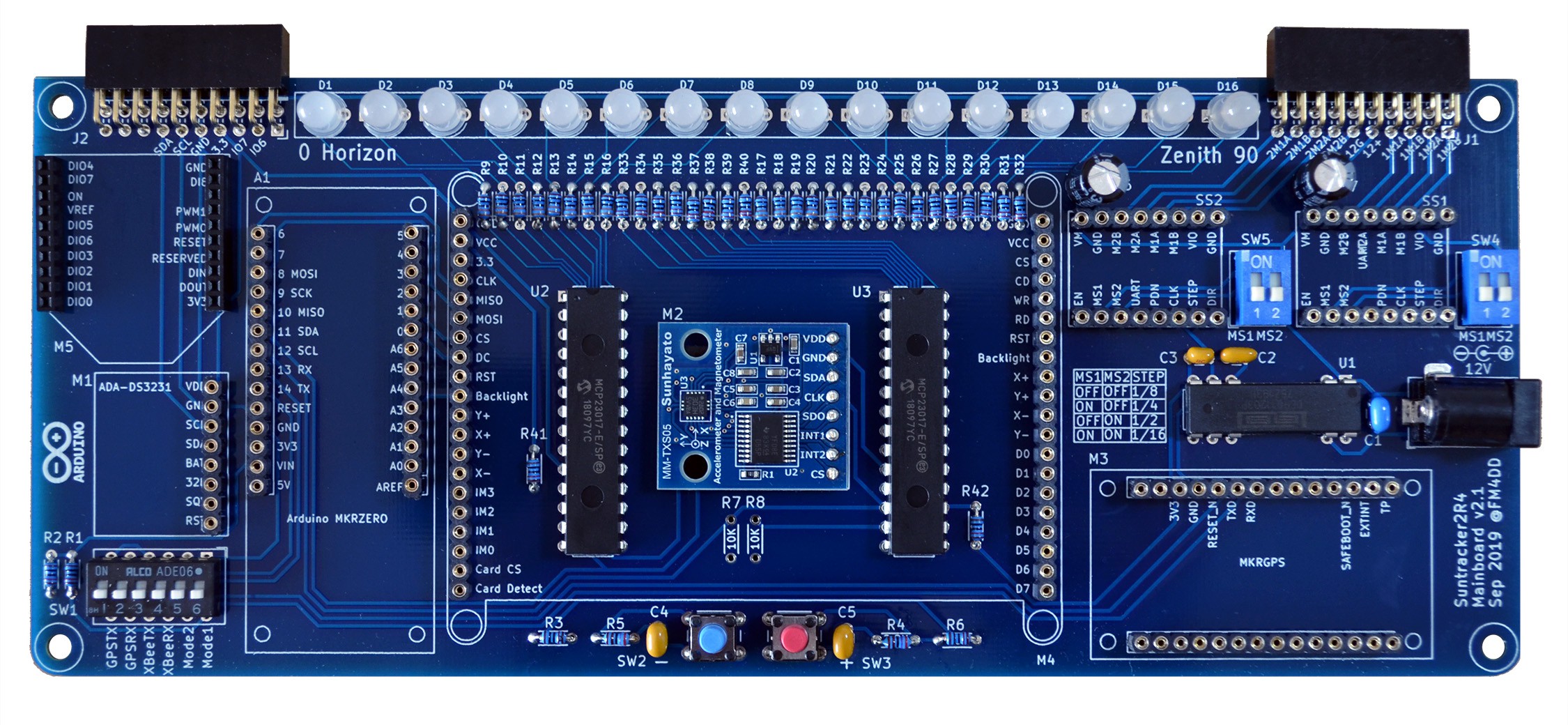
Here is the result of the stacked design, showing the placement of the magnetometer sensor and Zenith display LED IO expanders below the TFT screen. The biggest challenge was to fit the set of 32 current-limiting resistors into the TFT space. Other placement options didn't route as well. In the end it was tight but worked.

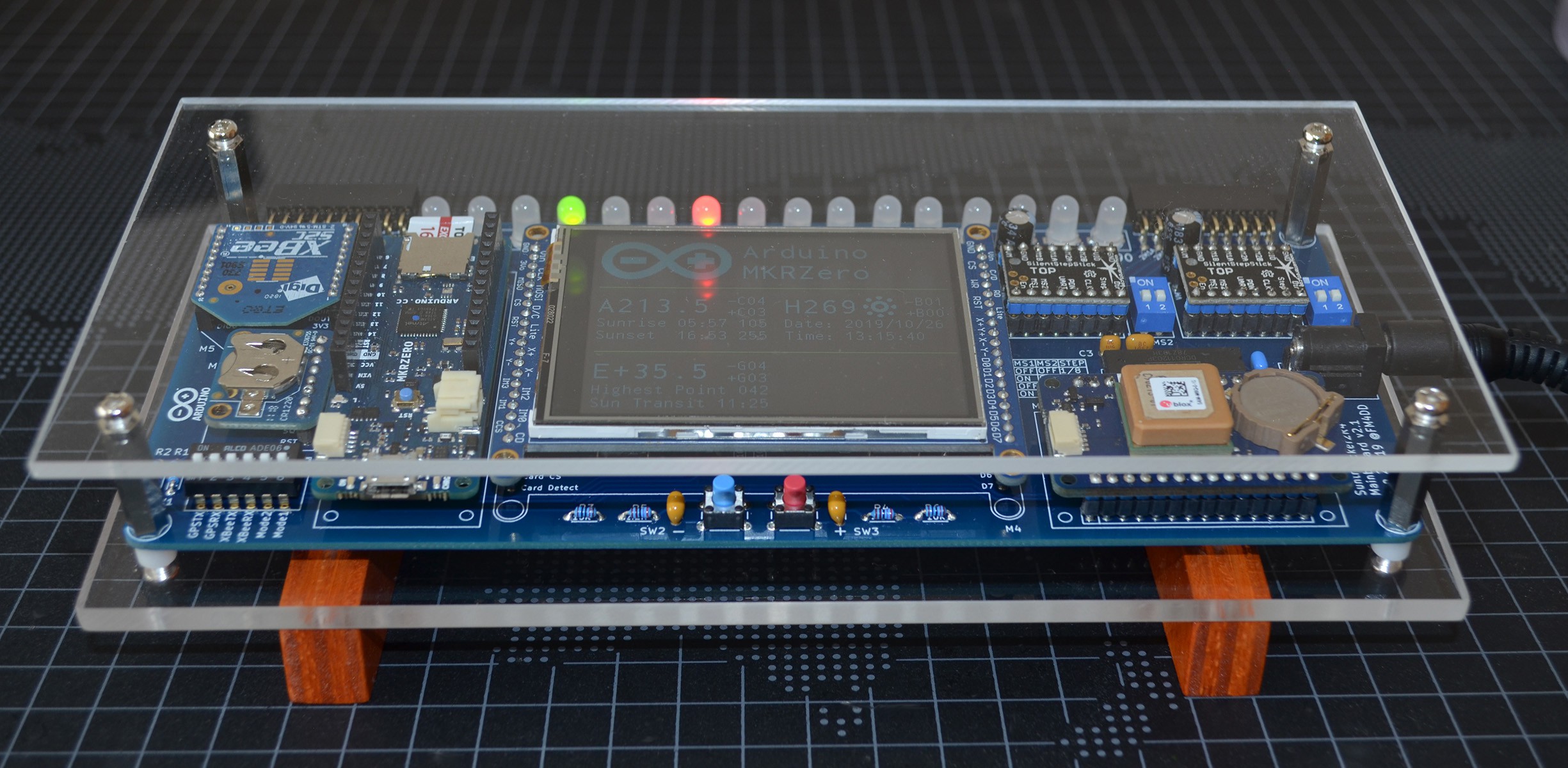
Below is the fully assembled mainboard. While the displayboard design is still sometime off, over the weeks I am going to work with the mainboard to write the code for the new modules. A simple frame as been fitted to protect the board during that time.

I was also relieved to see the new Texas Instruments power IC working. Since it was a new device I never used before, I missed one trace to the "enable" pin on the PCB. One small wire bridge later, the board powered up just fine.
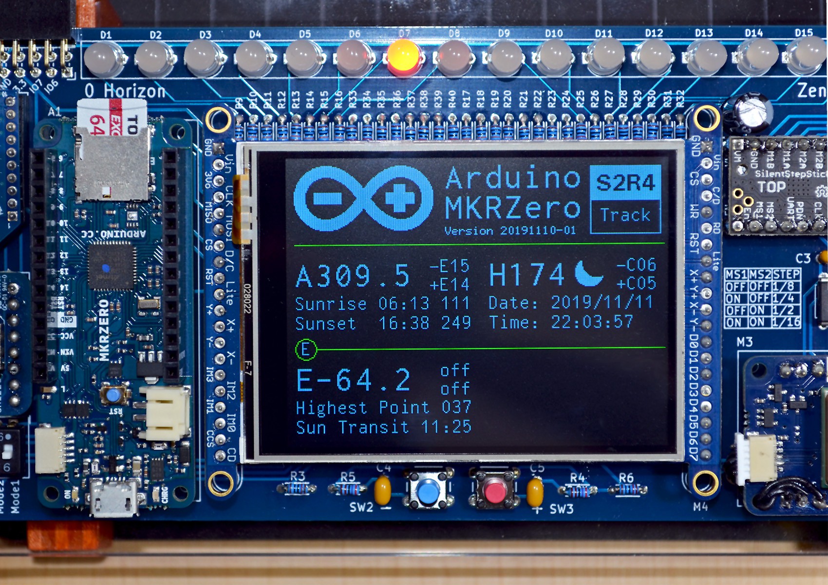
For more detail, this is the 2.8 inch TFT in its glory, increasing screen space more than 8 times over the previous oled. Since I was already short on MCU IO pins, I used SPI and quickly learned that screen refresh is slow. It requires careful updates to specific data only. The more pixel need to refresh, the slower it gets.

 Frank
Frank
Discussions
Become a Hackaday.io Member
Create an account to leave a comment. Already have an account? Log In.