shane.snipe
-
Adding Speed Control with a BLE App
12/28/2019 at 17:13 • 0 commentsOn one hand, this log is kludging together snippets of example code to control my speedster. On the other hand, this may also be my first noteworthy hack with it comes to how the motor is controlled. Enough spoilers, this is how I did it.
I have been working with Thunkable off and on for mobile phone apps. I had Thunkable classic working with BLE a couple of years ago but Thunkable X or cross platform did not support BLE until earlier this year. Now it is working and it is fast and it seems very robust. Check it out at thunkable.com. Here is the tutorial on BLE. https://www.youtube.com/watch?v=sNpCTsVifo4
The link to my project in thunkable is here. I will continue to work on this but hopefully it continues to be functional! https://x.thunkable.com/copy/8fb9477a0c64124cb1102b88990c27ed
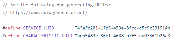
Obviously, there is some Arduino code that needs to interface with this app. This was my biggest concern when I watched the video but the example code written by Neil Kolban worked flawlessly once I got the UUIDs correct. Here is the code. It is a standard library example. https://github.com/nkolban/ESP32_BLE_Arduino/blob/master/examples/BLE_write/BLE_write.ino
So if you came across this hoping to figure out how to hook your ESP BLE to your phone the resources above were sufficient for me to get it going. The rest of this log is about my struggles and triumphs in bending the motors to my will.
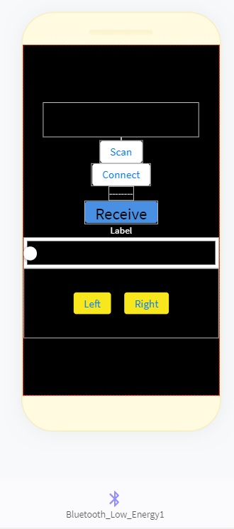
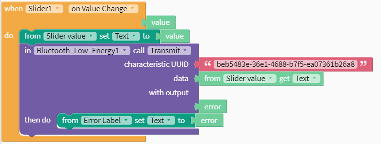
First you set up your interface and drop in you buttons, labels and sliders. You also need the invisible component the BLE. I know I am not winning any design awards with this one but it works!
The slider is meant for speed control and the left and right buttons are for turning.
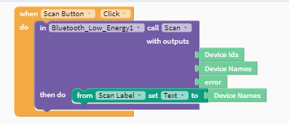
Here are the blocks I used and an explanation of my understanding of them. First you need to check if your targeted device is available so you use the scan function and print a list of available devices.
I have only used this with the live test function on thunkable so far and occasionally I will have to dump it and restart it to make sure I can see the ESP32. However, I have always been able to connect. The scan takes 20-30 seconds.
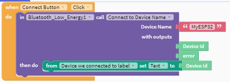
Next once you see your device pop up on the label, press the connect button and you get an immediate connection. There have been some discussions that the first scanning step can be skipped if you know your device is available. I have yet to try it. Here is the block for connection.
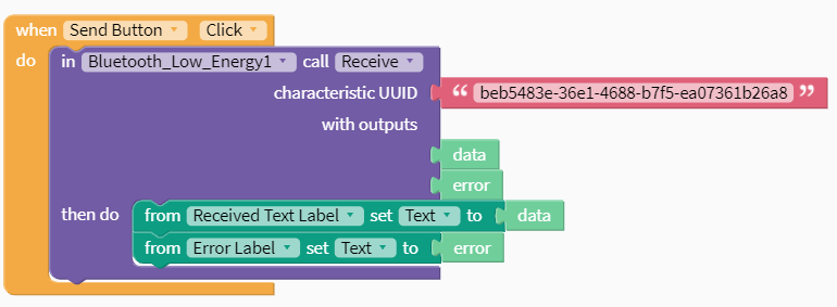
Now the Arduino code has some standard communication in it. It sends out Hello world until something has been sent to it and then it starts to echo what it receives. So to make sure I can hear from the Arduino I added a receive block.
So far I have not changed the UUID from the example code but there is link where you can get a new UUID.
I also included the error code if this is not working. So if I see Hello World or the value I am sending on my phone screen, I know my phone is communicating with the ESP32.
The next blocks are for sending data to the to ESP32 to control the movement.
The motors have a high and a low speed and an enable. The low speed still goes like 20 mph so it was not suitable for indoor use. I tried to pulse the enable at various PWM frequencies. However, Goldilocks was no where to be found. Either I pulsed to long and it shot across the room or it was I too short and it never really got going. So I was stuck! I considered just making it an outside bot and focusing on turning it but it is December in Chicago and it is too cold outside to run my bot.
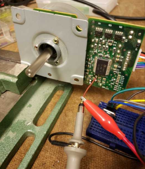
So here is my first real hack for this project. I remember the training I got when i was selling this motor 15 years ago. The motor has a look up table for the initial acceleration. Once it is up to significant speed, the speed is set by the frequency from the crystal. So there seemed to be a chance to replace the crystal with an external signal. Now this is why I belong to a makerspace. I may be able to come up with theories like this but I was not confident about how to test or implement this theory. Luckily we had a EE in the building and he encouraged me to get the motor running so he could check the signal coming out of the crystal with the scope. There was a crystal in and out on the schematic. We probed both sides of the crystal and saw a similar wave that seemed to be amplified on the out side. So we decided to see if we could use the function generator to make a similar wave to the input side wave. The wavelength was only 250 ns so it looked like a 4 mHz crystal. We got the crotchety function generator to make something with a similar frequency and high voltage. We then removed the crystal and attached a wire to the low side of the crystal input.
To my delight, the motor started running. We reduced the frequency on the generator and the motor slowed down and sped up accordingly. I have a box of these motors and this will make them much more useful.
I had been struggling to control speed and direction because I was trying to control the speed by turning on and off the motors. Now I have much finer control available.
The other issue I have been struggling with for the last year is how to go from the text that is easy to send with BLE to integers that can finely control my device. Going from the ESP32 to the App, apparently if you take your received text and store it as a variable you can change it to and integer.
https://community.thunkable.com/t/how-to-convert-my-text-number-into-math-block-number/71826
However, for this application I was going the other way. The character received in Arduino needed to be converted to my speed number. After various fails at type conversion, my makerspace came to the rescue again!
char inbyte=0;
char* p;
int i=20;class MyCallbacks: public BLECharacteristicCallbacks {
void onWrite(BLECharacteristic *pCharacteristic) {
std::string value = pCharacteristic->getValue();inbyte = value[0];
i=atoi(value.c_str());
Serial.println(i);I had a switch statement based on the first character in char inbyte. That worked fine I wanted finere resolution. i=atoi(value.c_str()); seems to have done it and it is working fine. I send an output from my slider in the app here and the speed updates dynamically from 0-50. 0 is off, 1-49 are pwm values and 50 is full on.
At this point, I only know how to send one value. Maybe if set up a different characteristic ID I can send a number to a separate variable on the ESP32 side. The problem is I may want to control the speeds of the two motors individually. Maybe two different sliders.
In any case the goal for today is to replace that frequency generator output with a output from my ESP 32. I will also try to add a second slider under a second characteristic uuid and callback and see if I can get two independent streams of data going so I can individually control the motors.
I suppose the other option is to have on slider from 1-100 and one from 101 to 200. Based on the number that is sent, the speed for the individual motor can be set in an if then statement.
-
Anatomy of the board
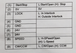
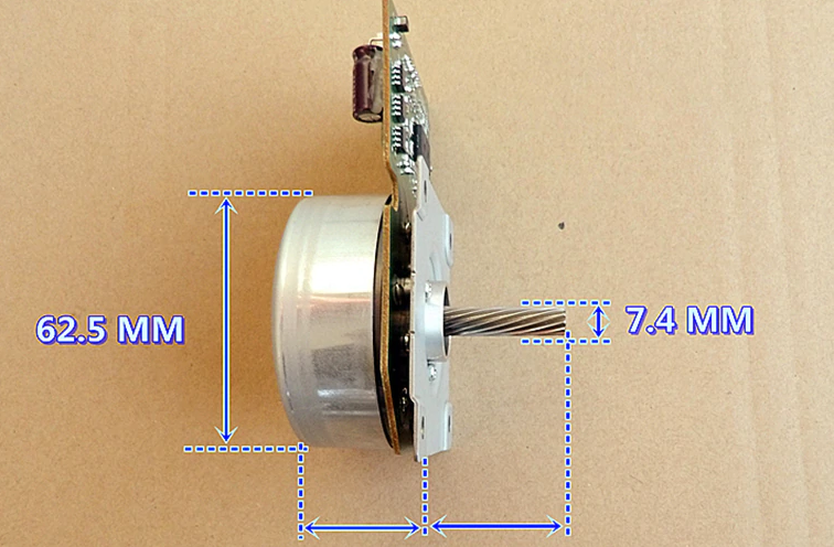
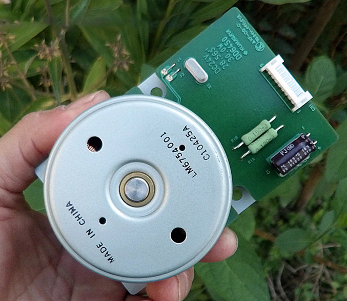
12/01/2019 at 18:54 • 1 commentI have always wanted to use the box of motors I had left over from the lead free transition to make some robots. The motors were the DD6450 motors and they 30W 24 V motors that spun at 2850 RPM. I had found some rubber rings that fit well over the motors and turned the outer rotors into wheels. The on board drivers made this motor pretty easy to drive with an Arduino but I wanted to be able to control it with my cellphone so we had a bit of 3.3V output from the ESP32 to 5V input problem. Here is the basic pinout:
So 24V runs directly from the battery so that is not an issue. Pins 1,2 and 8 work with 3.3V inputs. Pin 3 keeps the circuit running while not powering the motor. Maybe it is good for fast starts but I have not been using it.
The pin that has been a thorn in my side is Pin 9 CW/CCW. For some reason the 3.3V pin can not drive it. It actually does not run when attached to a ESP32. So to get around this sticky problem, I added a L293D motor driver. I use the 3.3V to switch the 12 or 16V coming in. I then drop it through a 5V regulator to drive the motor pin.
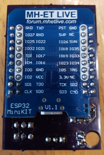
I wanted to make this controller as compact as possible, both to make it easy to mount and to save the cost of making the pcb. I used the MH-ET ESP32 shown below.
On the top side board I mounted the motor controllers, linear regulators and output pins. The ESP and the logic to drive the motors do not take much power so I did not attach the heat sinks to the back plane.
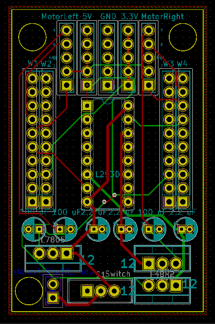
Full disclosure, this is a mechanical engineer making one of his first boards. It is functional but I can imagine I broke a hundred laws of elegant circuit design in making this happen. If anyone wants to school me in the comments, I am all ears. I probably would start with the power and ground inputs right next to the mounting holes in the bottom left corner above. I guess I am using nylon mounting screws!
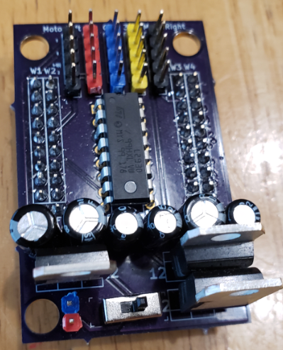
Here is the top of the board. This is actually a big step for me. Being a MechE I generally do not believe in capacitors but I put to see if it helps out at all. On other projects with this motor I have had some intermittent operation where touching the circuit made it work. It could have been a bad solder joint but after hearing of the story from Jeri Ellsworth on how the China fab team removed the capacitors and made her C-One project not work. She put her hand on it, changed the capacitance and figured out that she did not make a dud of an ASIC. In the abundance of caution, I added capacitors to this board. Lots of them!
Outside of this board, the robot will only need a terminal strip to attach the 12V-16V. I am leaning towards 4 x 18650s just because I do not have a battery holder for 3. I want to get the BMS going but the first round will charge outside of the robot.
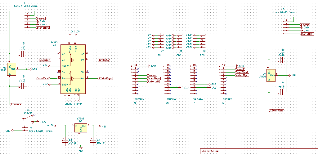
So from the top, the pinout is:
5) CW/CCW -- Pin 9 on the motor. This is boosted to 16V through the driver and then dropped to 5V. Pin 34 for the left motor and Pin 32 for the right motor direction.
4) Speed -- Next pin down is pin 8 on the motor, and 35 for the left motor and 27 for the right motor. There is a high and a low speed and low will probably be good for most driving.
3) Ground -- Pin 5 on the motor. Pin 4 will go to the ground on the power strip.
2) 5V -- This is Pin 2 on the motor. I believe this is what powers the electronics. My hope is that if this is off, the 24V wired directly from the batteries will not be drawing any current.
1) Start Stop - This should work as an enable, disable. It is pin 33 for the left motor and pin 25 for the right motor. Pulsing it may provide some crude PWM and make it somewhat possible to run this robot indoors.
For completion here is the Kicad board
I am not sure if anyone can find similar motors but if they are available, here is the board.
![]()
As a testament that you really can find anything on the internet, I actually found this motor being sold as surplus on Ali.
The connector shown in the picture is a PH 2.0 9 position. I really struggled with connections until I found this one. Here is a link.
And that is about as far as I have gotten on the electronics for this project. I will provide a programming update soon.
Two wheeled speedster
Drum motors from laser printers give this bot tremendous speed at a bargain. Scavenged parts robot with the BLE connection as a bonus!