-
1Step 1: Replace the power supply
![]()
(NB: These instructions were created after the fact, so no ongoing construction details or images.)
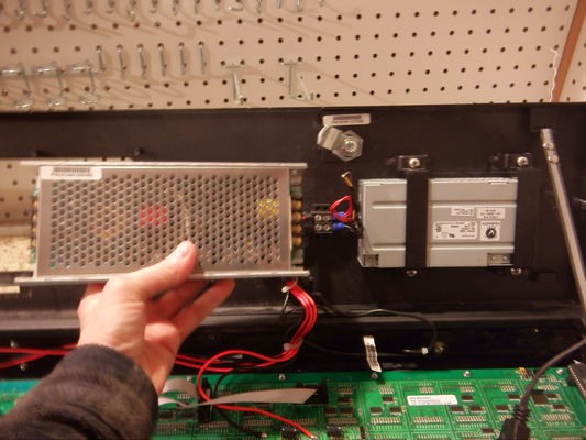
Vehicle electrics are a nominally 12 volts(*), and the original sign has a 12V to 5V power supply rated to 20 amps (in hand, in the image above).
So the first step in converting a sign is to replace the 12V input power supply with a 120V input one. The original supply has a standard form factor, so any supply in industrial form factor will fit in the original mounting straps.
This gives the sign a power switch, an IEC cord, and the ability to take power from a wall socket instead of a bench supply.
The current for a typical message was measured at 700mA, and I estimate that the maximum current will be around 2A with every LED lit. The original supply is wildly overspec'd for this application, I suspect this is for extra output capacitance: the extra storage will keep the sign lit if the bus voltage drops when starting the engine.
An old PC power supply will typically source more than 10 amps, and should work here as a replacement.
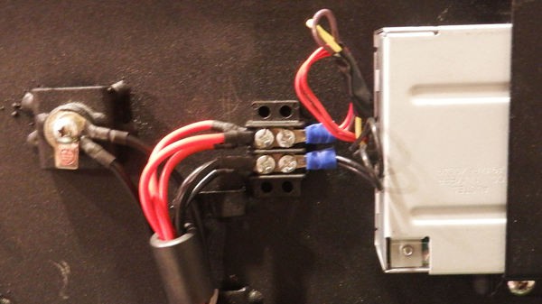
A small terminal block glued to the case keeps everything tidy. The unused 12V (yellow) and 3.3V (brown) from the new supply are taped and tied off.
(*) Broadly speaking, ignoring details
![]()
-
2Step 2: Determine the baud rate
![]()
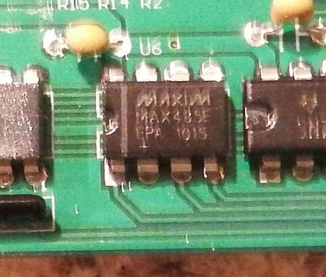
The Luminator sign contains a controller board (with keypad) connected to a separate LED board, the latter having it's own controller. In addition to the micros and some support circuitry, both boards have a MAX485 serial to RS485 converter.
![]()
So apparently the control board tells the LED board what to display using an RS485 interface. That's good news - it's easy to eavesdrop on RS485, and serial protocols are easy to work with.
![]()
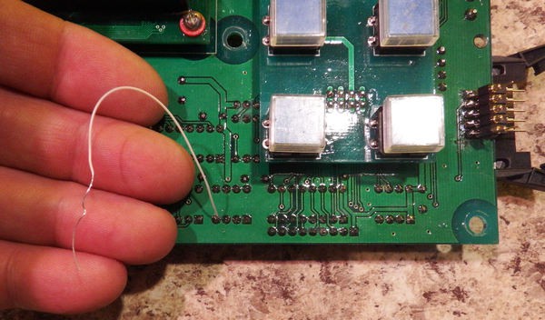
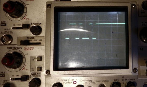
The first step is to determine the communication baud rate. After verifying that the input of the MAX485 is the Tx line of the microcontroller (as expected) attach a wire and view the data on a storage scope. One divided by the pulse time (1/t) is the baud rate.
![]()
For this Luminator sign, the rate is 19200 baud. The bits are sent in groups of 10, which corresponds to 1 start bit, 8 data bits, and 1 stop bit. The full comms spec is: 19200,8,N,1
-
3Step 3: Eavesdrop on the serial protocol
![]()
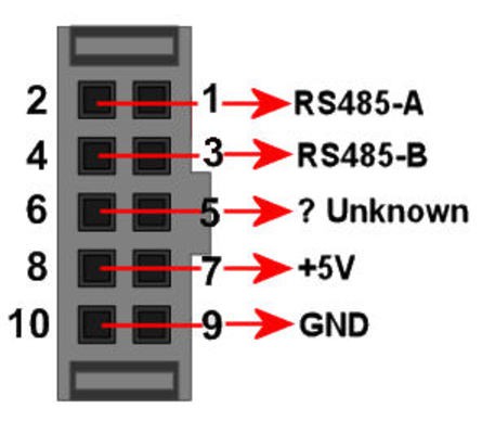
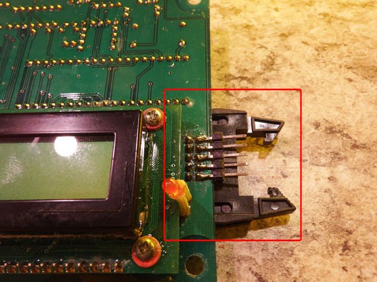
Buzzing out the serial cable connector shows the odd pins connected to the even pins. In other words, Pin 1 is the same as Pin 2, Pin 3 is the same as pin 4, and so on. The complete connector pinout includes the two RS485 lines, power, ground, and an unused pin
(I found an automotive bus standard that matches this pinout, but don't remember which one.)
![]()
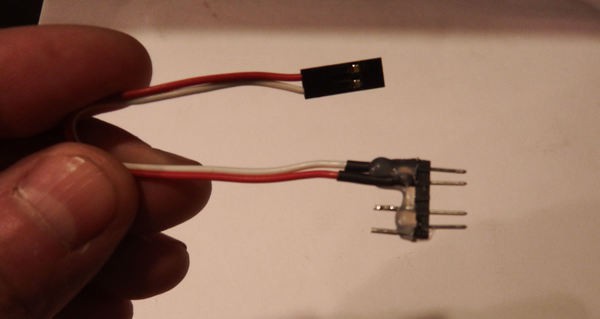
Jumpers are soldered to the connector plug, and connected to a Raspberry Pi using an RS485/USB converter. Connect the "A" line of the converter to the "A" pin on the sign connector (pin 1), and the converter "B" line to the "B" pin on the sign connector (pin 2).
![]()
The $2 RS485-USB converter from eBay enumerates as a serial device on the pi. Eavesdropping on the data is as simple as typing "cat /dev/ttyUSB0 >dump.txt".
-
4Step 4: Decode the protocol data
Dumping the data shows that the control board refreshes the sign information every 10 seconds or so. A complete dump of the image "EMERGENCY" looks like the following:
my $EBMsg = [                                   ### Emergency (bright) ###
            0xfc,                               # Start Byte
            0x00, 0x5f, 0x80, 0x01, 0x04, 0x11, # Header
            0x00, 0x00, 0x03, 0xf9, 0x86, 0x7f, 0x3f, 0x07, 0xe3, 0xf9, 0x86, 0x1e, 0x18, 0x60, 0x00, 0x00, 0x00,
            0x00, 0x00, 0x03, 0xf9, 0x86, 0x7f, 0x3f, 0x87, 0xf3, 0xf9, 0xc6, 0x3f, 0x18, 0x60, 0x00, 0x00, 0x00,
            0x00, 0x00, 0x03, 0x01, 0x86, 0x60, 0x31, 0xcc, 0x33, 0x01, 0xc6, 0x61, 0x98, 0x60, 0x00, 0x00, 0x00,
            0x00, 0x00, 0x03, 0x01, 0xce, 0x60, 0x30, 0xcc, 0x03, 0x01, 0xc6, 0x61, 0x98, 0x60, 0x00, 0x00, 0x00,
            0x00, 0x00, 0x03, 0x01, 0xce, 0x60, 0x30, 0xcc, 0x03, 0x01, 0xe6, 0x61, 0x98, 0x60, 0x00, 0x00, 0x00,
            0x00, 0x00, 0x03, 0x01, 0xce, 0x60, 0x31, 0xcc, 0x03, 0x01, 0xe6, 0x60, 0x0c, 0xc0, 0x00, 0x00, 0x00,
            0x00, 0x00, 0x03, 0xf1, 0xce, 0x7e, 0x3f, 0x8d, 0xf3, 0xf1, 0xa6, 0x60, 0x0f, 0xc0, 0x00, 0x00, 0x00,
            0x00, 0x00, 0x03, 0xf1, 0xce, 0x7e, 0x3f, 0x0d, 0xf3, 0xf1, 0xb6, 0x60, 0x07, 0x80, 0x00, 0x00, 0x00,
            0x00, 0x00, 0x03, 0x01, 0xfe, 0x60, 0x3c, 0x0c, 0x33, 0x01, 0xb6, 0x60, 0x03, 0x00, 0x00, 0x00, 0x00,
            0x00, 0x00, 0x03, 0x01, 0xb6, 0x60, 0x36, 0x0c, 0x33, 0x01, 0x9e, 0x61, 0x83, 0x00, 0x00, 0x00, 0x00,
            0x00, 0x00, 0x03, 0x01, 0xb6, 0x60, 0x33, 0x0c, 0x33, 0x01, 0x9e, 0x61, 0x83, 0x00, 0x00, 0x00, 0x00,
            0x00, 0x00, 0x03, 0x01, 0x86, 0x60, 0x31, 0x8c, 0x33, 0x01, 0x9e, 0x61, 0x83, 0x00, 0x00, 0x00, 0x00,
            0x00, 0x00, 0x03, 0xf9, 0x86, 0x7f, 0x30, 0xc7, 0xf3, 0xf9, 0x8e, 0x3f, 0x03, 0x00, 0x00, 0x00, 0x00,
            0x00, 0x00, 0x03, 0xf9, 0x86, 0x7f, 0x30, 0x47, 0xe3, 0xf9, 0x8e, 0x1e, 0x03, 0x00, 0x00, 0x00, 0x00,
            0xa3,                               # Checksum = sum between start/stop
            0xfb                                # End byte
        ];
My specific sign has 14 rows of 130 columns. Each display image consists of:
- A literal 0xFC, which begins a frame
- A 6-byte header
- 14 packets of 17 bytes, one packet for each row
- A checksum
- The literal 0xFB, which ends the frame.
The header
The 6-byte header comes in two forms: "Normal" and "Bright":
0x00, 0x5f, 0x80, 0x01, 0x04, 0x11, # Bright Header
0x00, 0x50, 0x80, 0x01, 0x04, 0x11, # Normal Header
The 2nd byte: 0x5F indicates bright, while 0x50 indicates normal intensity. Other values in this byte have no effect.
The final 9 bits (0x11 in the headers above) is apparently the number of bytes per row of data to be displayed. My sign has 130 LEDs per row, so 0x11 indicates 17 bytes per row (136 bits), with the final 6 bits unused.
The two bytes before the final (0x01, 0x04) is apparently the width in LEDs of the sign, left shifted by one.
The rows
After the header comes the row data: 14 rows, with each row described by 17 bytes of binary data. A "1" bit in the data indicates an "on" LED, and "0" is "off".
The checksum
The checksum is the arithmetic sum of the header and row data. Simply add together the header and rows, and truncate to 8 bits.
Escape codes
The protocol is resiliant against data loss, which means that if the START_FRAME (0xFC) or END_FRAME (0xFB) appears in the row/column data, it'll cause the LED board to re-sychronize the frame. This will result in an apparent broken packet, the checksum won't match, and the frame won't be displayed.
For this reason, START_FRAME and END_FRAME codes must be escaped when they appear in the data stream. The luminator sign uses the following escape codes:
0x1B becomes 0x1B, 0x00
0xFC becomes 0x1B, 0xE1
0xFB becomes 0x1B, 0xE0
The sign uses an ASCII escape char (0x1B) to escape the START_FRAME, END_FRAME, and ESC chars when they occur in the data.
This implies that an individual row packet can have more than 17 bytes: for each escaped character found in the data, the system needs an escape plus one extra char to describe the escaped data.
Thus, a sign display row might have a few more chars - more than the strict 17 needed to account for 130 columns - to describe any individual row.
Here's an example frame using the technique. Note that the header specifies 16 (not 17) bytes per row, and tows 6 through 12 have more than 16 bytes due to escapements:
my $PMsg = [ ### Call Police ### 0xfc, 0x00, 0x50, 0x80, 0x01, 0x01, 0x10, 0x00, 0x00, 0x00, 0x00, 0x00, 0x00, 0x00, 0x00, 0x00, 0x00, 0x00, 0x00, 0x00, 0x00, 0x00, 0x00, 0x00, 0x00, 0x00, 0x00, 0x00, 0x00, 0x00, 0x00, 0x00, 0x00, 0x00, 0x00, 0x00, 0x00, 0x00, 0x00, 0x1f, 0x1f, 0x1f, 0x30, 0x01, 0xf0, 0x43, 0x06, 0x00, 0x07, 0xe3, 0xe6, 0x0f, 0x3e, 0x7e, 0xc0, 0x3f, 0xbf, 0xbf, 0xb0, 0x03, 0xf8, 0xe3, 0x06, 0x00, 0x07, 0xf7, 0xf6, 0x0f, 0x7f, 0x7e, 0xc0, 0x31, 0xb1, 0xb1, 0xb0, 0x03, 0x19, 0xb3, 0x06, 0x00, 0x06, 0x36, 0x36, 0x06, 0x63, 0x60, 0xc0, 0x30, 0x31, 0xb0, 0x30, 0x03, 0x03, 0x1b, 0x00, 0x06, 0x00, 0x06, 0x36, 0x36, 0x06, 0x60, 0x60, 0xc0, 0x3e, 0x31, 0xbe, 0x30, 0x03, 0x03, 0x1b, 0x00, 0x06, 0x00, 0x07, 0xf6, 0x36, 0x06, 0x60, 0x7c, 0xc0, 0x1f, 0x31, 0x9f, 0x30, 0x03, 0x03, 0x1b, 0xe0, 0x06, 0x00, 0x07, 0xe6, 0x36, 0x06, 0x60, 0x7c, 0xc0, 0x01, 0xb1, 0x81, 0x80, 0x03, 0x03, 0x1b, 0xe0, 0x06, 0x00, 0x06, 0x06, 0x36, 0x06, 0x60, 0x60, 0x00, 0x31, 0xb1, 0xb1, 0x80, 0x03, 0x1b, 0x00, 0x1b, 0x00, 0x06, 0x00, 0x06, 0x06, 0x36, 0x06, 0x63, 0x60, 0x00, 0x3f, 0xbf, 0xbf, 0xb0, 0x03, 0x1b, 0xe0, 0x1b, 0x00, 0xf7, 0xe0, 0x06, 0x07, 0xf7, 0xef, 0x7f, 0x7e, 0xc0, 0x1f, 0x1f, 0x1f, 0x30, 0x01, 0xf3, 0x1b, 0x00, 0xf7, 0xe0, 0x06, 0x03, 0xe7, 0xef, 0x3e, 0x7e, 0xc0, 0x00, 0x00, 0x00, 0x00, 0x00, 0x00, 0x00, 0x00, 0x00, 0x00, 0x00, 0x00, 0x00, 0x00, 0x00, 0x00, 0x00, 0x00, 0x00, 0x00, 0x00, 0x00, 0x00, 0x00, 0x00, 0x00, 0x00, 0x00, 0x00, 0x00, 0x00, 0x00, 0xc6, 0xfb ]; -
5Step 5: Wiring in a Raspberry Pi
![]()
We're ready to control the sign with a RasPi, without the original motherboard.
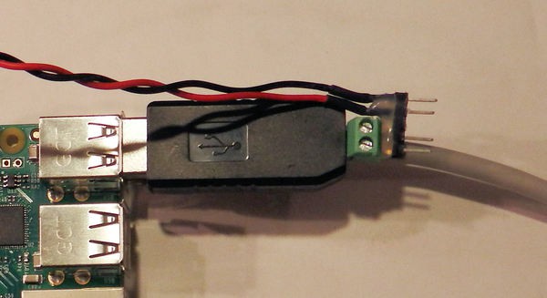
Take a 5 pin header, cut away the middle pin, solder a power connector to pins 4 and 5, and add some hot glue as a strain relief.
![]()
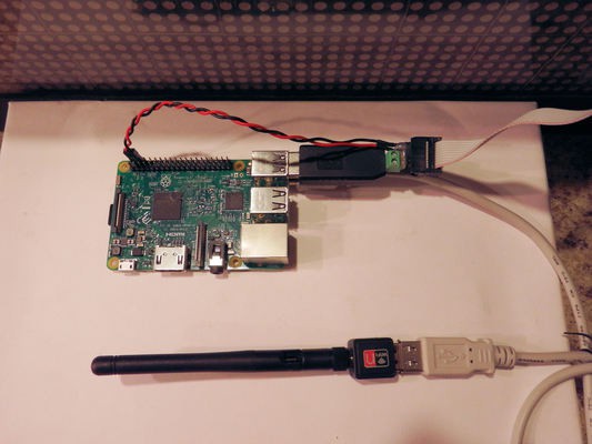
One side of the header is wired directly to the RS-485 converter and screwed down. The +5V/Gnd connector powers the RasPi through the I/O connector as shown below.
NOTE: Power connection uses pins 4 and 6 of the RasPi I/O connector, NOT pins 2 and 4. The connector (below) is on the upper row, one pin to the right from the leftmost pin.
![]()
Because the RasPi wifi won't work from inside the (metal) sign enclosure, I'm using an external Wifi dongle on a USB extension cable. Mount the dongle and external antenna somewhere on or outside the enclosure.
-
6Step 6: Software control
As part of the project I've included an executable RasPi program to continuously read a local directory and display the image files it finds there.
(See the "files" section, on the left side of the project webpage.)
You upload files to the system using any method you like: ssh, web page (that you write), samba share, E-mail process (that you write), physically copying files to the memory stick, or whatever.
A directory listing of the RasPi user is as follows:
$Home/
    bin/
        Luminator.pl
        DevServer.pl
    Display/
        01-05N-Amherst.bmp
        02-05N-Makerspace.bmp
        03-05B-Makerspace.bmp
        04-05N-Makerspace.bmp
        04-05N-RepairCafe.bmp
        05-05N-Hackaday.png
    Images/
        Amherst.bmp
        Hackaday.png
        Makerspace.bmp
        RepairCafe.bmp
    Fonts/01-05N-Amherst.bmp
        VCR_OSD_MONO_1.001.ttf
    logs/
        ...
    lib/
The "lib" directory is unused in this project.
The "logs" directory contains serial output from the program. If you encounter problems, you might find useful information there. (Also, check /var/log/syslog for messages containing the string "Luminator")
The "Fonts" directory contain an open source bitmap font that works well for my (130x14) sign. Install it on your system and use it to create messages
The "Images" directory contain some pre-built images. The display program can handle most image formats, including jpg, gif, tiff, and bmp.
The "Display" directory is where the displayed files live. The file naming format is:
- 2 digits to determine the file sort ordering
- 2 digits of seconds to display the file
- B for "Bright", or N for "Normal"
- Ignored section
- Extension
So for example, the file "03-05B-Makerspace.bmp" says:
- It's the 3rd file in the sequence
- It's shown for 5 seconds
- At bright intensity
The files in Display/ can be symbolic links, so you can delete the links without deleting the actual data. You can have holiday messages in the Images directory, and only link to them during the holidays.
A display time of 0 seconds means "forever". A display time of 1 second is bumped up to 2 seconds, since the LED board takes a minimum of 2 seconds to display an image (and loading images any faster will confuse it).
To have the RasPi automatically run the display program on boot, put the following at the end of /etc/rc.local
rm -f /home/Luminator/logs/logs.bak3/* 2>/dev/null mv -f /home/Luminator/logs/logs.bak2/* /home/Luminator/logs/logs.bak3 2>/dev/null mv -f /home/Luminator/logs/logs.bak1/* /home/Luminator/logs/logs.bak2 2>/dev/null mv -f /home/Luminator/logs/logs.bak/* /home/Luminator/logs/logs.bak1 2>/dev/null mv -f /home/Luminator/logs/logs/* /home/Luminator/logs/logs.bak 2>/dev/null nohup /home/Luminator/bin/DevServer.pl >/home/Luminator/logs/logs/DevServer.log 2>&1 & #nohup /home/Luminator/bin/Server.pl >/home/Luminator/logs/logs/Server.log -v 2>&1 &![]()
 Peter Walsh



Discussions
Become a Hackaday.io Member
Create an account to leave a comment. Already have an account? Log In.