Michael Gardi
-
WDC-1 Presentation
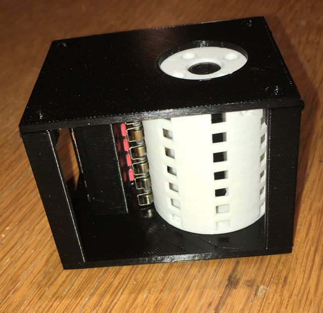
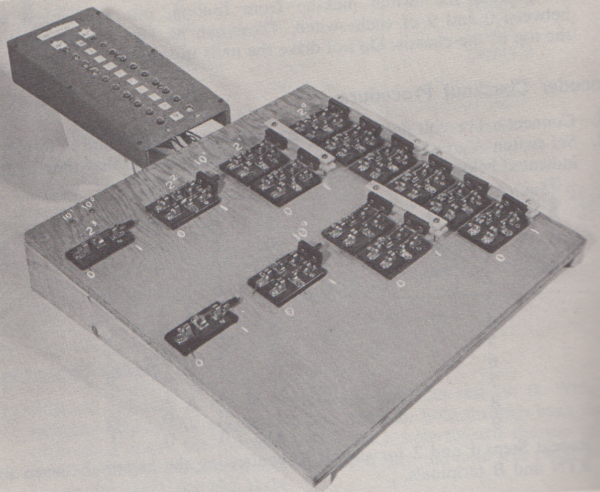
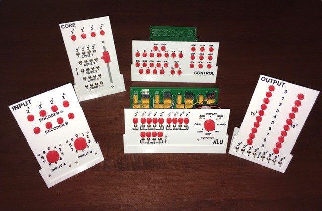
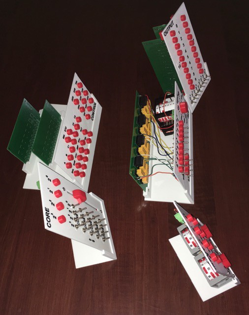
01/05/2020 at 15:20 • 0 commentsWith some of the components finished, I started thinking about what the final project would look like. My initial thought was to build a slanted console and arrange the panels on top much like the CT-650 pictured in the Description above or a Minivac 601. But when I started thinking about Max Maxfield and Joe Farr's talk about implementing their computer as a: "...a series of glass-fronted wooden cabinets" plus the very nature of the Working Digital Computer as a teaching tool I changed my mind. Instead I designed some simple stands to hold the panels upright at a small angle:
![]()
![]()
The components will be wired together with quick connects so they can be easily detached and examined. It's my convertible with the top down look.
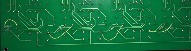
BTW here is a sneak peek at my Control Panel implementation with a clue to where I will be going with it.
-
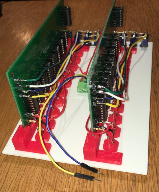
WDC-1 ALU Panel Done
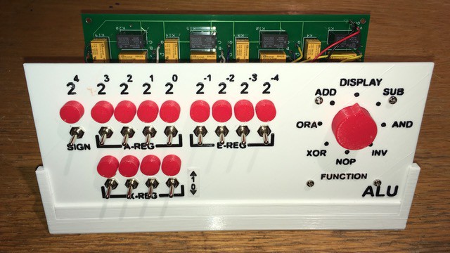
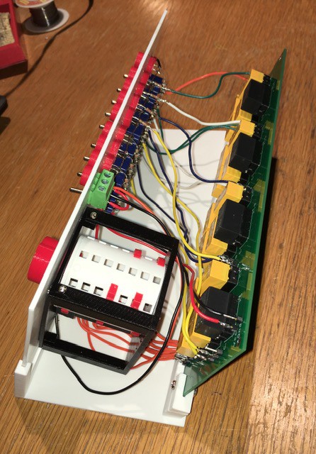
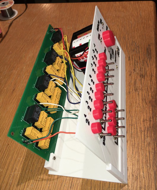
01/05/2020 at 14:41 • 0 commentsI got the ALU wired up and ready to go...
![]()
![]()
![]()
There were a few issues to be resolved that were discovered when "integration testing" the whole unit.
- The first was easy. XOR was not working as expected. It turned out I had messed up the Encoder Pegs for XOR. Rearranged pegs. Done.
- On a more serious note both ADD and SUB, the two operations that I actually need for a Working Digital Computer were not working either. Checked the Encoder Pegs but no joy I had installed them correctly. Turned out there were two distinct issues.
- For ADD, when creating the 4-Bit ALU PCB I had crossed the Q and Co pins. Needed a little surgery to fix.
![]() I have updated the PCB layout to reflect this.
I have updated the PCB layout to reflect this. The operation of SUB as defined isn't quite right. A + NOT B is not the whole story, there needs to be a +1 in there to get the two's complement. Fortunately I noticed that the GS2 control line was not being used by any of the operations I had defined. So I was able to tie that input on the PCB to ground and use the GS2 switch on the encoder to control the Ci input on the PCB. So now the SUB operation (only) has a Peg in the GS2 position which makes the Carry In bit high introducing the required +1.
All operations are now working as expected.
-
WDC-1 ALU Panel Implementation
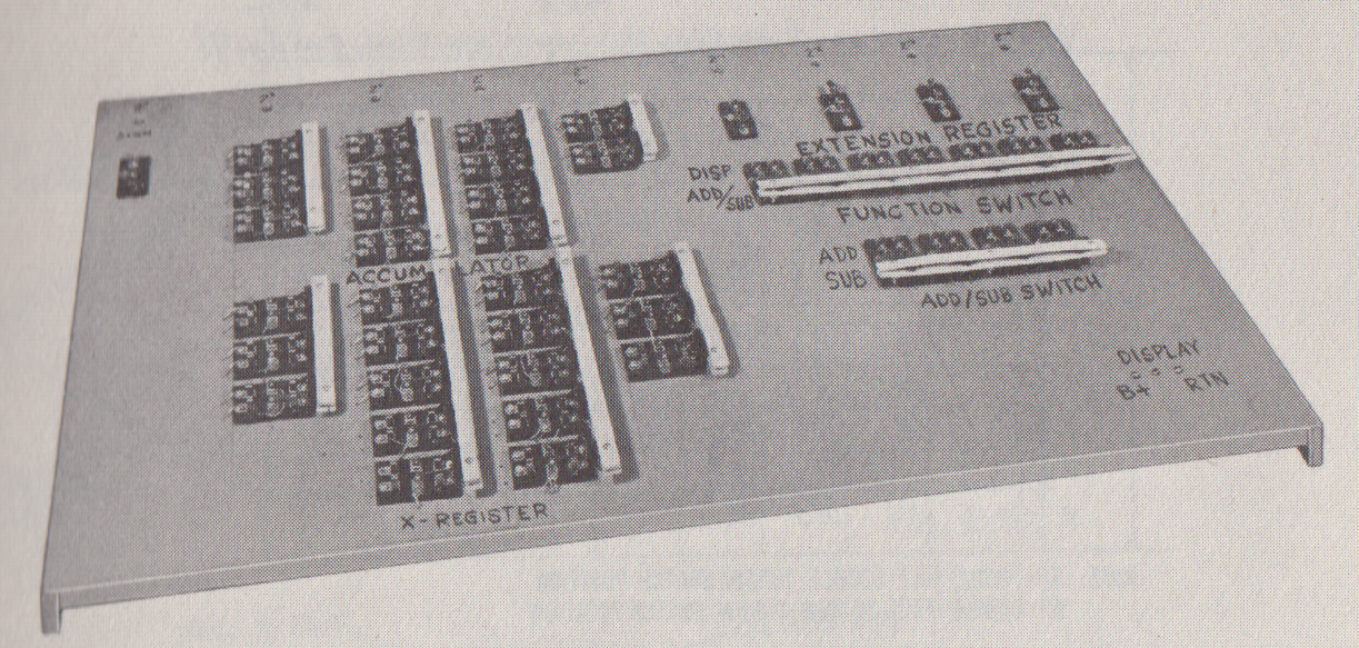
12/30/2019 at 00:41 • 0 commentsThe ALU presented in the book was even more massive than the Binary to Decimal Decoder consisting of 39 DPDT and 5 SPDT blade switches mounted of a 24 x 36 inch board. Like the Decoder the ALU switches were physically "ganged" together to perform the ADDition and SUBtraction operations.
![]()
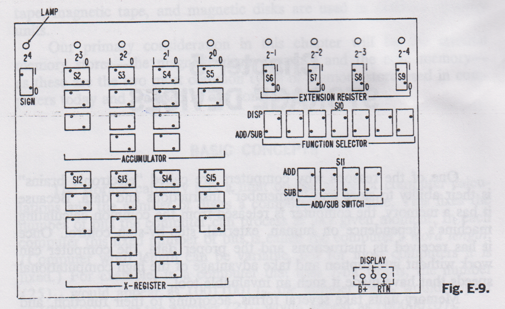
The panel was laid out like this:
![]()
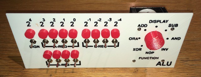
In addition to the "sets" of switches to enter the Sign, Accumulator, X-Register, and Extension Register binary values, there were switches to choose between Functions (Display or Add/Sub) and the Operations themselves (Add or Sub). Now with the new ALU functionality baked into the Relay Based ALU PCB, this layout can be simplified quite a bit. Here is my ALU Panel:
![]()
I've incorporated DISPLAY into my single FUNCTION selector switch and added 5 new operations: ORA, AND, XOR, INV, and NOP. As with the Binary to Decimal Decoder the PCB will be mounted behind the panel. Time to get wiring.
-
WDC-1 ALU Technology
12/27/2019 at 20:18 • 0 commentsWith the Input, Output, and Core Panels done it was time to tackle something a little more challenging, the ALU. Since I had a small stash of signal relays burning a hole in the bottom of my parts bin (graciously donated to my makerspace Kwartzlab Makerspace), that was the implementing technology of choice.
As an aside, about the time that "How to Build a Working Digital Computer" was published, I was making simple relay based "computers" (like a tic-tac-toe machine for example). We had a family friend that worked for Bell (the local telephone exchange not the Labs), and as a result I had access to literally miles of 22 AWG solid core copper wire (unlikely to happen today). I made my own hand wound relays with bolts, nuts, washers, L-brackets, and tin strips cut from cans for contacts (so many scapes and cuts). Fun times.
At any rate I don't think I had occasion to use relays again until I built my Minivac 601 Replica, and of course now. When I did a search for "Relay ALU" I was astonished how much work has been done in this area, hundreds if not thousands of man hours of effort. I looked at ideas from the pioneering work of Konrad Zuse to more recent contributions by roehl and others right here on Hackaday.io. At the end of the day I came to the same conclusion that Dylan Brophy did and chose this 1-bit Relay ALU designed by Dieter Mueller:
![]()
Such a cool design. It was a good fit for the DPDT and SPDT relays (with polarized coils) that I had on hand and provides a lot of functionality for the part count (overkill for this project actually). Truly standing on the shoulders of giants here folks.
So after a successful breadboard test:
![]()
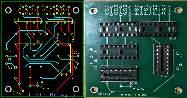
I designed and tested a 1-bit ALU PCB.
![]()
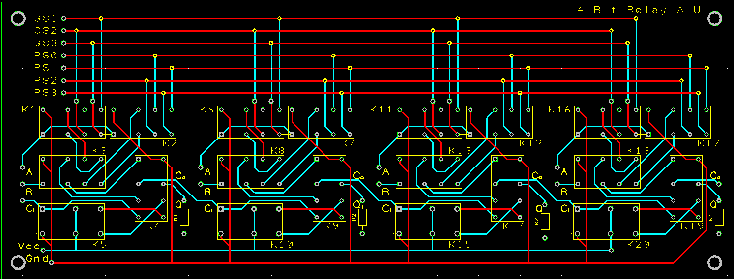
My initial thought was to stack 4 of these but at the end of the day I decided on a 4-bit ALU PCB to minimize the wiring:
![]()
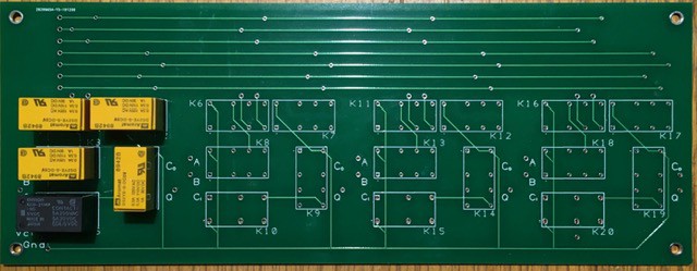
The actual board was from the same batch where Top Documentation text was not silkscreened on:
![]()
Also limiting resistors have been added to the design after this board was produced. As you can see, as of this writing, I've just started populating this board.
This ALU is of a multiplexer design with the operation to be performed controlled by the 7 inputs GS1-3 and PS0-3. So from Dieter's site here are some examples for configuring the multiplexers to work as Logic Units:
  GS   PS
 3210 3210
 ~~~~ ~~~~
 0000.1010 Q=A             DISPLAY A
 0000.0101 Q=/A            INVERT A
 0000.1110 Q=A|B           A OR  B
 0000.1000 Q=A&B           A AND B
 0000.0110 Q=A^B           A XOR B
 1000.0110 Q=A+B           A ADD B
 0010.1001 Q=A+/B=A-B      A SUB B
With that kind of capability I could not resist extending the ADD and SUB operations that the WDC-1 ALU needs to perform with the following optional operations:
- DISPLAY
- AND
- ORA
- XOR
- INV
- NOP
To select between these 8 options I'll need another Encoder. With a few tweaks to my Decimal to Binary Encoder design I created a 1 to 7 Encoder for the ALU:
![]()
Pretty much ready to assemble the ALU. -
Output Panel Done
12/26/2019 at 17:33 • 0 commentsI got the second Binary to Decimal Decoder wired and installed:
![]()
Testing:
![]()
With the Output Panel done moving on to the ALU.
-
The Output Panel
12/24/2019 at 20:54 • 0 commentsWhen I was thinking about and doing research for this project I happened upon the following article Building a 4-Bit Computer: Relay Based Hardware Accelerators by Max Maxfield. This and it's associated articles were very interesting and informative. At one point Max and his collaborator Joe Farr talk about implementing the computer: "...the idea is that we will have a series of glass-fronted wooden cabinets mounted on the wall. One will contain the Clock Generator, another will contain the CPU, and yet another will contain a Programmer’s Console...", much like the Working Digital Computer's design I thought. The part that really caught my interest was:
"The fun thing is that the contents of each cabinet will be realized using different implementation technologies, including relays, vacuum tubes, transistors, jelly bean 74-series logic chips, magnetic logic, pneumatic logic, fluidic logic… we are limited only by our imaginations."
That did sound like fun so I decided that this is what I would do as well.
Getting back to the Output Panel. While the Output Display part was relatively compact, the Decoder circuit to power it was enormous consisting of 12 DPDT and 2 SPDT blade switches mounted of a 15 x 15 inch board.
![]()
At first I thought that I might implement the Decoder with relays rather than hard wiring it since a bunch of 5V signal relays had just been donated to my makerspace (Kwartzlab Makerspace). I found the following circuit:
![]()
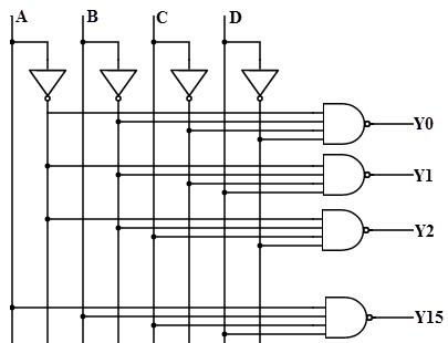
It would cost 7 DPDT and 1 SPST relays per decoder, and I would need at least two decoders. Not bad, but making even two decoders would eat up most of my stash of relays and I was pretty sure that I would need more than two decoders for the rest of the build. So I turned my attention to the 7400 series ICs. Since the 7400 series of TTL logic integrated circuits was introduced in October 1966 I felt they were mostly "on-side" for this project (remember my goal is "period technology" with modern fabrication). I had not actually ever implemented anything substantial with 7400 logic so I was intrigued. The following circuit seemed both simple and elegant:
![]()
This circuit would require 1 SN7404 (Inverter 6-Channel ) and 5 (since I would only implement for 0-9) SN7421 (Dual 4-Input AND Gate). At a cost of less than a dollar per chip pretty reasonable. Having decided on the technology the next step was implementation. Proto board and point-to-point wiring was certainly an option but at the end of the day I chose to design a PCB. I had not done any PCB layout for quite some time and I had forgotten how much I enjoyed doing this work, getting the parts into just the right orientation for a clean board. Mind you I have never done anything really sophisticated, just simple 2 layer work like this one:
![]()
Now the board is wired for the full 16-bits of output, but for the decoders only 10-bits will be used. And the board:
![]()
turned out pretty good. Some of the text was in Top Documentation not Top Silkscreen so didn't get printed, plus I have since added the limiting resistor for the LEDs to the board but it will do for my purposes.
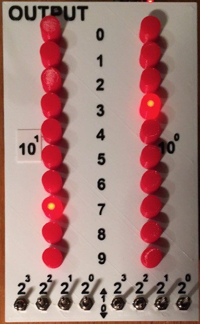
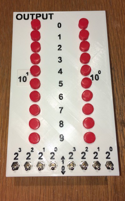
With the 7400 based Decoders, the 15 x 15 inch board from the book has been reduced to a single row of toggle switches and a couple of PCBs. Here is my Output Panel:
![]()
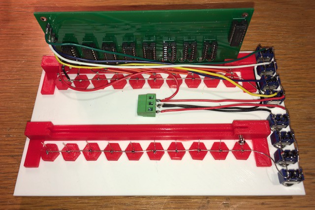
Here is the back:
![]()
I have designed and printed a couple of brackets to mount the PCBs. One Decoder is wired in and working with the second to follow shortly. Each of the four switches' common lead is connected to the corresponding Decoder input on the board (1, 2, 4, 8). When the switch is set to the down position (0) the input receives a LOW signal. When in the up position the switch signals HI. Works great.
-
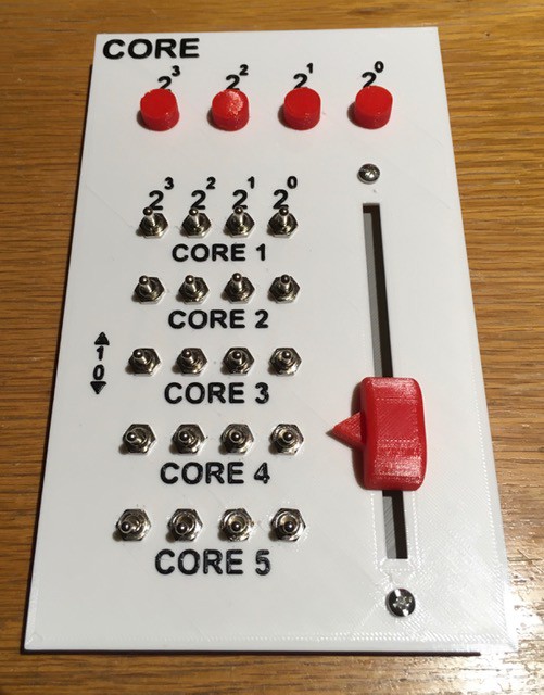
Core Panel Done
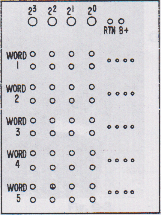
12/23/2019 at 21:50 • 0 commentsHere is the diagram from the book showing the "Core Memory" panel:
![]()
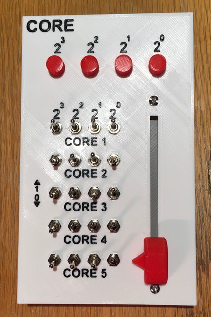
From my log post Switch for the Core Panel I have opted to implement a slider switch to select the Core "Words". Here is my finished panel:
![]()
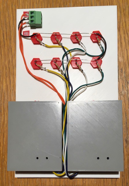
The switches are wired much like a keyboard, with a diode for each switch to prevent "ghosting".
![]()
The way it's wired it looks like core memory a bit don't you think?
![]()
Here it is in action...
-
A Switch for the Core Panel
12/19/2019 at 19:56 • 0 commentsMost sizeable projects involve a number of side trips, and this one is no exception. From the Core Memory section of the book: "To read [core] memory, use the clip lead to simultaneously connect all four exposed wires for the address desired. See Fig. F-9."
![]()
In adherence to my no paperclip policy for this project I had to come up with an alternate method of selecting one of the five core memory "words". Looking closely at the CT-650 image below it looks like they used a rotary selector switch.
![]()
Cool, I could use a variant of my Mostly 3D Printed Rotary Switch, but when I started laying out the Panel it felt more like a slider switch would be a better fit. So I took a little side trip and designed one (based on my rotary switch).
![]()
The STL files and and construction details can be found in my Instructable: Mostly 3D Printed Slider Switch.
Here is a sneak peek at the Core Panel with the switch installed and a "fancy" knob. The Panel still needs to be wired.
![]()
-
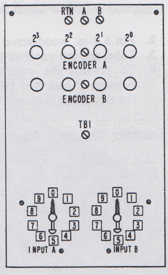
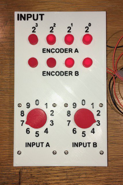
WDC-1 Input Panel Finished
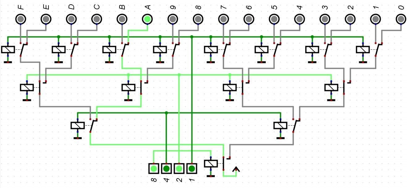
12/18/2019 at 20:35 • 0 commentsNot much to say here. The Input Panel has been implemented using two of my Binary Encoders. From the book, the diagram of the Binary Encoder Panel looked like this:
![]()
Here are some pictures of my implementation:
![]()
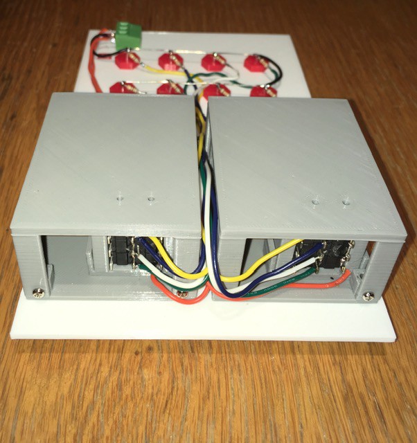
Wiring:
![]()
![]()
Pretty close I think. Ready to be wired into the rest of the panels.
-
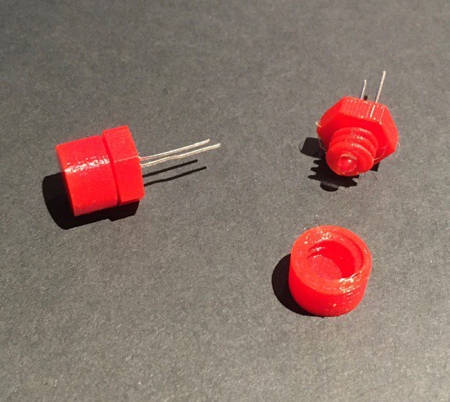
Panel Mount LED Socket
12/12/2019 at 16:30 • 6 commentsJust a small thing but I know I am going to need at least 40 console lights (try 86 when done) for this project. I'm also trying for a "vintage" look. So I come up with these based on the panel lights from the GENIAC computer:
![]()
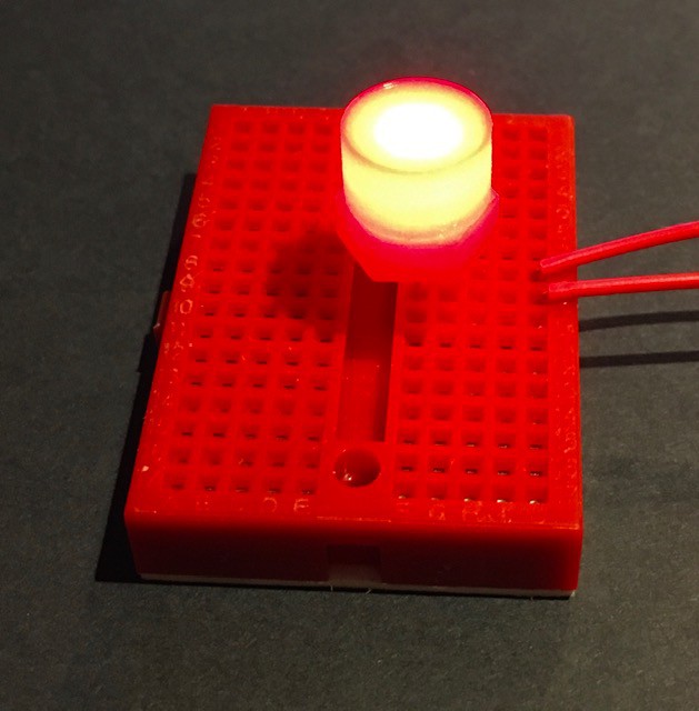
The picture below does not do justice to how nice these look when lit:
![]()
Bonus these are really inexpensive to make, a few cents each. The cheapest I could find on Digi-Key was about 50 cents. I have posted the STL files and printing instructions on Thingiverse: Panel Mount LED Socket.
WDC-1 a "Working Digital Computer"
Make a computer based on the book "How to Build a Working Digital Computer" by Edward Alcosser, James P. Phillips, and Allen M. Wolk
 I have updated the PCB layout to reflect this.