Close
0%
0%

Let me control you: Hitachi air conditioner

An attempt to wirelessly control an old Hitachi air conditioner

Similar projects worth following
My attempt to wirelessly control that old Hitachi air conditioner in my living room.
Not a classic one way communication system but one with feedback so I can detect any change done via the IR remote control but also know the unit status at any time.
The ultimate goal is to build a custom Zigbee controller for it so I can add it to my future home automation system.

I recently moved from the North of Tokyo to a new apartment situated 40km south but just 25min by train from my workplace. Bathroom and toilet separated, big kitchen, a proper living/dining room and an overall size of twice what I used to have.

There is 2 air conditioners to cool/warm up all that space:

  • one in the bedroom, quite recent and powerfull
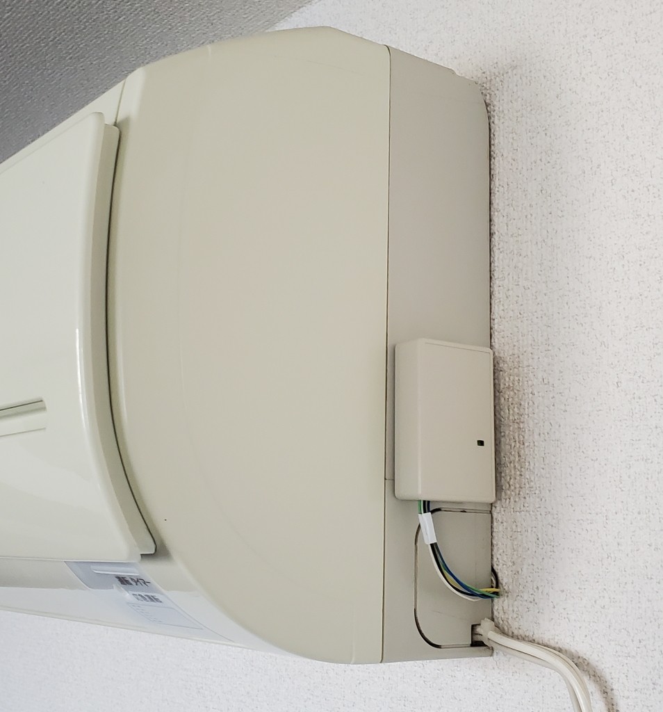
  • one in the living/dining room, fairly old and just powerful enough

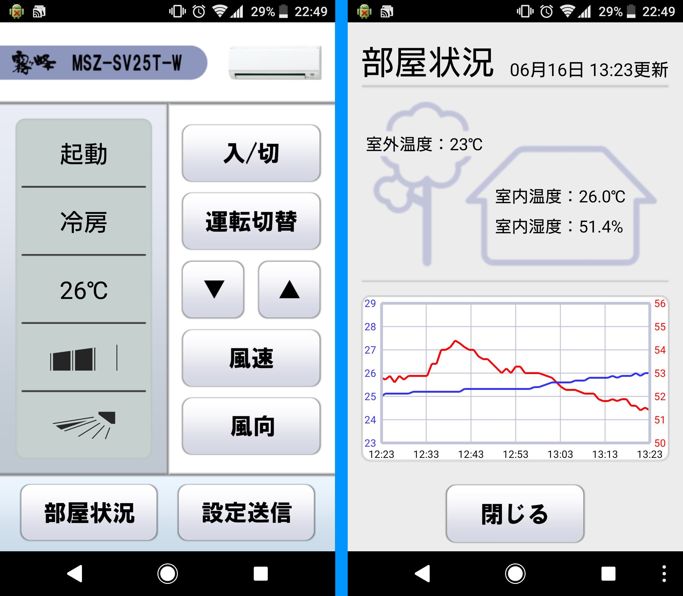
In my previous apartment, I had only one air conditioner that I controled with the dedicated remote control but also with my phone thanks to a WIFI enable IR remote control and Android app I made.

It was my first project since I moved to Japan 9 years ago and took me 7 months to complete.

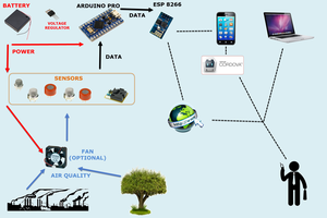
Arduino, ESP8266, FUSION360, MIT App Inventor, ThingSpeak... I learnt a lot and was able to brush up my skill in C/C++ a little bit.

Only downside of this solution was that I couldn't know if the air conditioner properly received the command sent and once I used the normal remote control my system would be completely desynchronized.

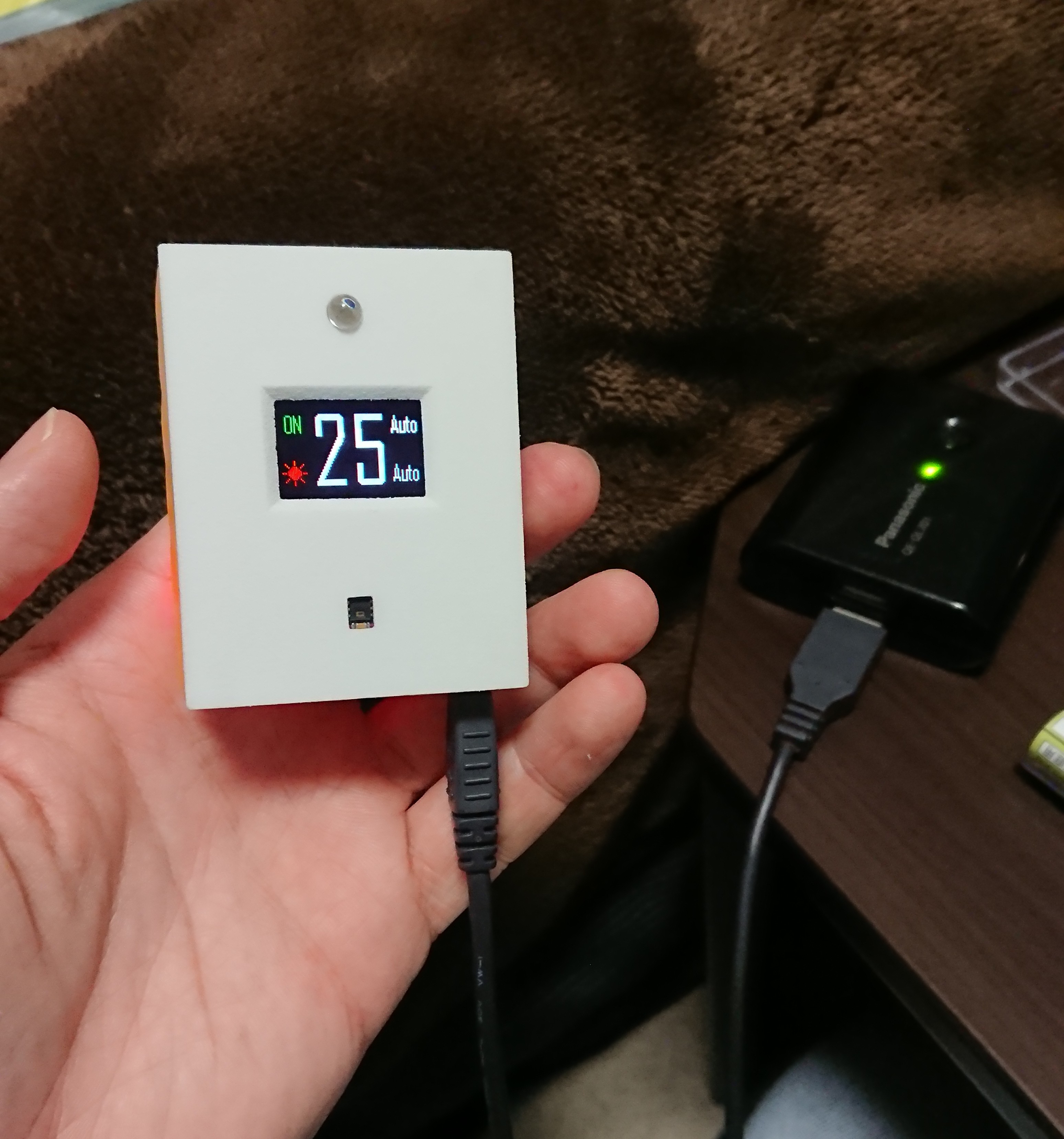
For this reason, this time I want to implement a kinda of feedback so I dont' have to worry about my system being synchronized or not. I don't plan to make another IR remote or repurpose the one I built before but rather investigate to see if there is a way to talk directly with the mainboard of the air conditioner.

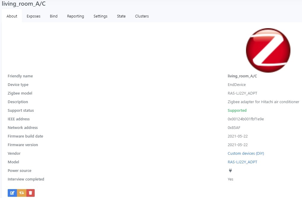
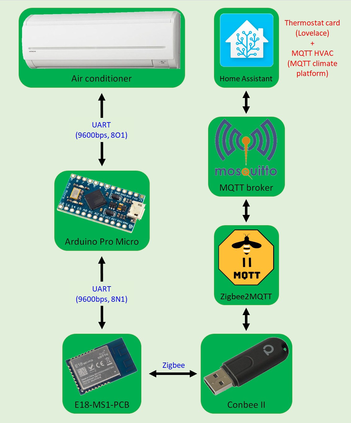
Moreover, I'm also digging in home automation and I plan to install a rather simple system based on Home Assistant and Xiaomi temperature sensor (Zigbee type).

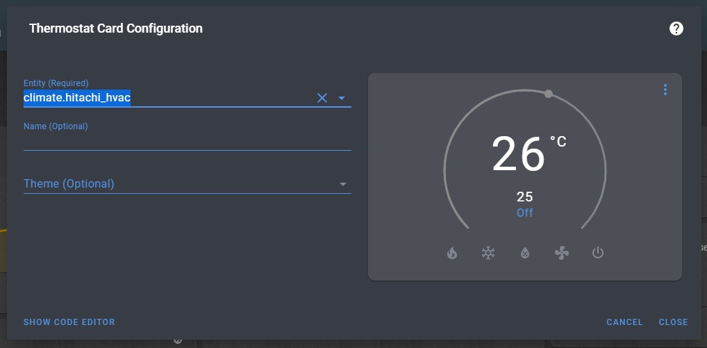
The ultimate goal here is to be able to control both air conditioners directly via Home Assistant so I don't have to fear a really cold room when coming home in the winter neither to deal with an overwhelming hot apartment in the middle of summer.

climate_platform.yaml

climate platform I added to the configuration.yaml of HA

yaml - 1.21 kB - 05/25/2021 at 13:37

Download

A-C_Hitachi_converter.js

external converter for Zigbee2MQTT

javascript - 1.05 kB - 05/25/2021 at 13:37

Download

my_puny_program.ino

small program that serves as an intermediary between the air conditioner and the Zigbee modul

ino - 8.29 kB - 05/25/2021 at 13:37

Download

CC2530ZNP-with-SBL (Z-Stack 3.0.2).hex

Z-Stack 3.0.2 ZNP with booloader firmware for CC2530 (power sleep disabled, alternative pinout option activated)

hex - 680.76 kB - 08/02/2020 at 06:53

Download

CC2530ZNP-with-SBL (Z-Stack 3.0.2).bin

Same Z-Stack 3.0.2 ZNP with bootloader firmware for CC2530 but in bin format (to be used when flashing using a LOLIN Wemos D1 mini and CC loader library)

octet-stream - 256.00 kB - 08/02/2020 at 06:53

Download

View all 10 files

  • 1 × Ebyte E18-MS1-PCB Zigbee module based on CC2530
  • 1 × XIAO Seeeduino SAMD21 based small microcontroller

  • Wiring diagram? Ok :)

    Florian01/02/2022 at 04:50 0 comments

    Some people commented asking if I could share a final schematic or wiring diagram, so here is a rather simple wiring diagram of my final board.

    Hope it helps some of you.

  • All done!

    Florian06/05/2021 at 06:05 0 comments

    The cheap plastic box I ordered on Amazon took quite some time to arrive... until I realized it was shipped from China.

    The size is just perfect. I cut a few holes, one for plugging in a USB-C cable (to allow direct reprogramming without having to take everything out of the box), one for the cable from the air conditioner, and I added a small light pipe so the microcontroller LEDs could be seen. Everything was secured using my best friend number 2, hot glue.

    The final result looks like this (the case held with Blu Tack):

    I may redo the cable that connects to the air conditioner motherboard, but for now, I'm happy with how it looks.

  • That looks far better

    Florian05/29/2021 at 00:37 0 comments

    Do you remember how my circuit looked before? It was basically just components on a breadboard, connections made with jumper wires, and a tiny power bank to supply power.

    Now it looks like this:

    I switched from an Arduino Pro Micro to a Seeeduino XIAO simply because I had a few on hand and wanted to make the final board as tiny as possible (it's only 40 x 60mm). The 7805 package size is definitely overkill for this circuit, but that was the only through-hole 5V regulator I had lying around.

    I also ordered a tiny plastic case on Amazon, which should be delivered next week. I’ll finish the project with a log of the complete product.

  • And that's how it's done

    Florian05/25/2021 at 12:51 3 comments

    I did it... I achieved my goal... I can now control my air conditioner from Home Assistant!
    I'm so happy and proud of myself!

    Everything happened so quickly in just one week that I can hardly believe it. Here's a brief summary of what I did and how:

       1. Using this GUI tool, I created a firmware with the following settings:

    • Board type = CC2530
    • Device type = End device without routing
    • Status LED = P22, Sending reports
    • Output 1 = P03, UART, Baud rate = 9600, Packet end = 0x0D
    • Model ID = RAS-LJ22Y_ADPT (for an unique name)
    • Set default reporting interval(s) = 60
    • Update firmware's timestamp

       2. Before closing the GUI tool, I used "Save custom converter for Z2M" to create the corresponding external converter for Zigbee2MQTT (see file A-C_Hitachi_converter.js).

       3. I flashed my Zigbee module, powered it up and then moved to Zigbee2MQTT dashboard in Home Assistant to add it. It appeared as an unsupported device with the name "RAS-LJ22Y_ADPT", so I followed the indication on this page and added it without any issues. 

       4. Then I moved the external converter I previously created to /config/zigbee2mqtt/.

       5. Back to Zigbee2MQTT dashboard, I went to Settings > External converters, entered the name of the converter, clicked "Submit" and restarted Zigbee2MQTT. The result is as follow.

       6. I added a climate platform to my configuration.yaml following this documentation (see file climate_platform.yaml for more details.) and restarted Home Assistant.

       7. In the meantime, I wrote a simple program that retrieves the air conditioner’s status every 2 seconds, compares it to the previously known status, and if different, sends the new status to Home Assistant in a JSON format. Additionally, this program sends setting commands to the air conditioner based on what it receives from Home Assistant (see file my_puny_program.ino for details).

       8. Finally I added a "Thermostat card" in Lovelace and set the "Entity" to the climate entity I created.

    I played a lot with this "Thermostat card", also played a lot with the infrared remote control and so far, everything works flawlessly, everything is in perfect sync. Only problem is how the material solution looks like for the moment...

  • It's... it's working... for real!

    Florian05/16/2021 at 08:28 0 comments

    I spent my Golden Week holidays diving deep in this GUI tool, and after a week of trial and error, I finally managed to send and receive data from Home Assistant!

    How do you ask?

    1. first, in Home Assistant, I switched from deCONZ to Zigbee2MQTT plus Mosquitto broker.
    2. using the GUI tool, I created a custom firmware with OUTPUT1 set to P0.2, configured to UART with a baud rate of 9600 and 0x0D as an end packet.
    3. I then flashed my Zigbee module with that custom firmware.
    4. in Home Assistant, from Zigbee2MQTT dashboard, I allowed devices detection by clicking "Permit join (all)".
    5. I then connected my Zigbee module to my FTDI USB to TTL Serial Adapter, powered it up and opened Termite on my computer.
    6. After about 20 seconds, a new device appeared in Zigbee2MQTT dashboard. I renamed it "Proto" and added it to Home Assistant.
    7. Then, I went to Configuration > Integrations > Mosquitto broker > Configure and in "Publish a packet", I wrote the payload "test" to the topic zigbee2mqtt/Proto/set/action.
    8. Like magic, the text "test" appeared in my Termite window.
    9. I returned to Home Assistant and this time, in "Listen to a topic", I entered zigbee2mqtt/Proto/action and clicked "START LISTENING".
    10. Back to my Termite window, I typed "test again" and... again like magic, the same text appeared in Home Assistant.

    Following this small success, I read here and there about how air conditioners are typically controlled via Home Assistant, and it's all about creating a "climate entity" and using the "thermostat" card in Lovelace.

    Thankfully, I found that there's a way to create such a climate entity when using MQTT: MQTT HVAC
    Perfect! This week, I'm going to search for more examples on how to create such an entity and try to build on. 

    Now that I’ve successfully transmitted data to Home Assistant, the overall connection diagram should look something like this:

  • Could that be the solution?!

    Florian05/03/2021 at 02:38 0 comments

    Today, I took a closer look at some sites introducing DIY Zigbee devices and noticed something right away: the author is using the same Zigbee module as I am (E18-MS1-PCB from Ebyte).
    In the past, I tried to look for projects or information about this CC2530-based module, but didn't find much. However, I thought it was worth another try since someone is actively building Zigbee devices with it.

    As usual, I used my best friend Google. Using the keyword "E18-MS1-PCB", I went right away to "Images" and after scrolling for a but, this caught my attention:

    I mean... the image title speaks for itself, right? With high hopes, I clicked on the image and was directed to Z1 Mini Development Board lets you build custom ZigBee end devices. Unfortunately, after reading the article, I didn't find anything new on the horizon. To be sure, I checked the linked Wiki page, and there I found this:

    Great firmwares? For the CC2530 chip... For a moment, I thought these might be the firmwares for the DIY Zigbee devices I mentioned earlier. Or maybe ready-to-flash firmwares to use a CC2530 as a ZNP device?

    Well, it turned out to be even BETTER than that: A GUI tool for creating your own alternative Zigbee device with a flexible configuration of inputs and outputs.

    This is incredibly promising and might be the solution I’ve been looking for to easily make a Zigbee device to enable connectivity for my air conditioner with Home Automation. I’ll be spending this Golden Week holiday diving into this!”

  • Long time no see ... (/ω\)

    Florian05/01/2021 at 02:22 0 comments

    A bit more than a year since my last project log entry... shame on me. COVID-19 pandemic got me stuck in an unpleasant and depressfull work - eat - sleep repeat cycle. My procrastination reached it's highest of all time level and even completing or starting a new DIY project didn't seem to motivate me enough.

    But I decided to put things in order and deal with my procrastination: completing this project while taking care of myself (personal training gym? skin care? improve my wardrobe?). Once this project is done, I will move to automate the other air conditioner I have and finally the small heater I bought last winter for my bathroom. From then I'm thinking to hack and improve the video intercom (bigger screen, adding a recording function, adding an auto-response function in case nobody is home, ultimately link it to HA?) but that's a story for another time.

    Okey now let's talk about what's new since ... well since last year: last time I successfully flashed a cheap CC2530 based module with Z-Stack 3.0.2 but not knowing a thing about Zigbee I didn't know what to do next. So I went on a frenetic search of information, hoping I would be able to gather enough material from articles/forum messages/videos or whatever to understand how to properly communicate with a Zigbee router and implement that in a structure I could program.

    Unfortunately the result was frugal:

    With that arduino program along with TI and NXP documents, I thought I could understand what should be done, in which order and manner but it turned to be far more difficult that I imagined and I gave up (at least for me it was too time consuming and fruitless). 

    So I turned my attention to public available litterature and bought the following book:

    which turned out to be a waste of time and money as it isn't a practical development handbook as stated in the front cover but rather a book that explains in depth Zigbee standard, its functionality and its radio signal implementation.

  • Successful flashing of Z-Stack 3.0.2

    Florian08/02/2020 at 06:34 0 comments

    I finally received my CC debugger (a cheap knockoff from AliExpress) and immediately set to work flashing my CC2530 module: success!

    For those interested in the process, I followed this documentation on using the TI SmartRFR software to flash the module. The firmware I used was based on Z-Stack 3.0.2, built following this tutorial I mentioned before (you can download the hex file from the Files section: CC2530ZNP-with-SBL (Z-Stack 3.0.2).hex).

    To check that the flash was successful, I used the TI Z-Tool software (don't forget to check "Scan all Enabled com ports (startup and manual scan)" in Tools > Settings > Serial Devices > Auto Scan). 

    While waiting for my CC Debugger to arrive, I looked around on the Internet for possible reasons why my previous attempts might have failed. Although I didn't find anything directly related, I decided to take a closer look at my components and found out the solder joint of D5 on my Wemos D1 mini was cracked... A quick rework and I successfully flashed the firmware using CC loader library (for those interested, I also uploaded the bin file in the Files section).

  • Zigbee, my future nemesis?

    Florian07/19/2020 at 06:09 0 comments

    Now that I've demystified the communication protocol of the Hitachi air conditioner, it's time to tackle what is gonna be the most difficult and time-consuming part of this project for me: building a Zigbee interface to enable remote control from Home Assistant.

    For the past month, I've been gathering information, learning the basics of Zigbee, searching for hardware solutions and trying to get a Zigbee module working. Here is a summary of my progress:

    1) I learned there is three different types of devices in a Zigbee network: router, coordinator and end device. Because I want to go for a simple solution, I will make an "end device".

    2) Searching for DIY Zigbee solutions led me to XBee modules and CC2530 based modules.

    3) After considering the XBee modules, I found them to be too large for my needs. I then researched the CC2530, a System-on-Chip (SoC) made by Texas Instruments. It can be programmed directly (Intel 8051) and used stand-alone or flashed with specific firmware to function as a ZigBee Network Processor (ZNP) with an external MCU (like controlling an ESP8266 with an Arduino via AT commands). Since my 8051 programming skills were rusty and I wasn't interested in learning the SDK, I decided to go with the ZNP solution.

    4) I searched for a CC2530-based modules on AliExpress and found a cheap and small transmitter/receiver module. Here is a link to the actual product: https://www.aliexpress.com/item/32803052003.html?spm=a2g0s.9042311.0.0.40bc4c4dzhaeel

    5) I received the modules in about 2 weeks. I made a simple breakout board for one and tried to flash Z-Stack 3.0.2 following this excellent tutorial. Since I didn't have a CC debugger, I used an alternative flashing method with a Wemos D1 and CClib (source: Zigbee CCLib Flashing). The flashing was successful but the module UART didn't seem to work. I checked that P2_0 (CFG1) was tied to GND and I carefully followed the CC2530-ZNP power-up procedure described in Z-Stack ZNP Interface Specification, but I never got the SYS_RESET_IND from the module.

    6) I tried reflashing the module using another programming method with CCLoader (tutorial: flashing CCLoader), but despite a successful flashing it still didn't work.

    7) I tried flashing various firmwares (router, coordinator, stock) that I found on forums and GitHub using both flashing methods. I also tried flashing the second module I received, but none of the attempts got the UART working.

    8) I've now ordered a CC debugger from China in the hope that the problem lies with the flashing method... Until I receive it, I plan to continue researching information about end device firmware, the Zigbee communication work-flow and Home Assistant integration.

  • Well... that was fairly easy

    Florian06/14/2020 at 03:10 1 comment

    Yesterday, I hooked up the "central station" and recorded a bunch of data. I tried as many settings as I could, focusing on identifying how commands are sent to the air conditioner and how status are retrieved.

    And after just two hours of opening PulseView files, extracting data and compiling everything in Excel here are the result.

    • status inquiry

          - RAC adapter message: MT P="address" C="checksum"[CR]

          - air conditioner response: OK P="value" C="checksum"[CR]

    • value setting

          - RAC adapter message: ST P="address","value" C="checksum"[CR]

          - air conditioner response: OK[CR]

    That's all there is to it! The checksum calculation is straight forward, so I won't go into details here.
    For a list of available addresses and possible values, check out the file "Analysis result (2020_06_14).xlsx".

    As a confirmation, I connected my FTDI USB to TTL serial adapter directly to the air conditioner, grounded the H-LINK pin and sent a few commands to the air conditioner: everything worked fine.

    So the next step will be to learn about Zigbee communication system and explore how I can implement a wireless remote functionality in Home Assistant.

View all 19 project logs

Enjoy this project?

Share

Discussions

Matthew wrote 12/29/2023 at 09:00 point

I found this project while looking for IR codes for a Hitachi aircon however this is way more intriguing. I have a more modern (2018 model) Hitachi RAS-EL56G2. Because of the slow speed of change for industrial manufacturers, I have a feeling it might still be possible to adapt this to current models.

Did you figure out the name of the type of connector for CN7? It looks a lot like a Molex 51103-0600 but it's slightly different. A little digging in the web archive to a hackaday project you linked, showed that it's likely a PAP-05V-S (or PAP-05V-R) connector. Was that the case for you?

  Are you sure? yes | no

Florian wrote 12/29/2023 at 09:28 point

Thanks for your comment Matthew. I invite you to check the log titled "The light at the end of the tunnel?" where you will see that CN7 is a PA-6P-TOP from JST. In the same log, you will find a link to the connector datasheet.

  Are you sure? yes | no

Matthew wrote 12/29/2023 at 09:36 point

Thank you Florian! I should have read the description in the images. I am facepalming as it is obvious now.


This is a JST PA connector, 6 pin. Thankfully can be found at my local electronics shop for ¥15 each, with the pin contacts for ¥50 for 10.

Cheers! Thank you for the hint!

  Are you sure? yes | no

Konsts wrote 08/08/2021 at 19:18 point

Wow! cool! Can you attach a wiring diagram?
I have a modern air conditioner Hitachi (RAK18RPD), but the connection is similar to yours, I wanted to try to repeat your project for integration into HA
Thanks!

  Are you sure? yes | no

Vince wrote 07/05/2021 at 10:15 point

Hello Florian

Congratulation !

What a good ... and quick.... job !

2 additional questions :

Could you confim the voltage used for serial com ? 5V ? 

Would it be possible to share the final schematic ?

Many thks

  Are you sure? yes | no

Florian wrote 07/05/2021 at 22:22 point

Thanks. 

I was highly motivated to finish this project and I managed to do so faster than I expected (•‿•)

The serial communication with the air conditioner is 5V while the one with the Zigbee module is 3.3V.

I didn't draw any schematic because there is only a very few parts but if I found timw this week I may upload a simple one.

  Are you sure? yes | no

Vince wrote 05/26/2021 at 11:58 point

Thanks for sharing your progress !

Whats are finaly the commands that you implemented ?

  Are you sure? yes | no

Florian wrote 05/26/2021 at 12:30 point

I went for something simple:

- power (ON, OFF) with address 0x0000

- operation mode (heat, dry, cool, fan only) with address 0x0001

- fan speed (auto, high, medium, low) with address 0x0002

- temperature setting (16 to 32 degrees) with address 0x0003

- room temperature with address 0x0100

  Are you sure? yes | no

Vince wrote 05/26/2021 at 13:42 point

This will cover a lot of use cases.
May be I would add some combined functions like :

1. Leave home function (some sort of eco mode) with less agressive desired temp and less fan spped)

2. a scheduler like the integration available in HA : "Scheduler integration". 

That would alow to manage overnight periodic operating

3. A/C technical alerts : but I still have no idea how it works....

  Are you sure? yes | no

Florian wrote 05/01/2021 at 01:32 point

Thanks for your comment.

First... so sorry for this late reply. 

Following your question I did a few tests and here is the result: even if pin 6 isn't tied to GND, the air conditioner will respond to MT commands. However, it would not respond to any ST commands.

  Are you sure? yes | no

Caleb Bramwell wrote 10/12/2020 at 20:23 point

Fascinating read, great work! Did you find you needed to control the H-Link pin6 line in the end?

  Are you sure? yes | no

Similar Projects

Does this project spark your interest?

Become a member to follow this project and never miss any updates