Chris Combs
-
Finishing touches: 2019-12
12/31/2019 at 22:40 • 0 commentsThe prototype software worked fairly well. I tuned it further to eke a few more frames per second (examples: skipping displays if their contents hadn't changed, using i2c block transfers, rewriting some pixel effects in scipy), and ended up around 27fps for most of the renderers.
Fast forward a year! I got distracted with some other projects.
I showed the prototype in another art show at VAE Raleigh in the fall of 2019.

(did I mention it has some text based easter eggs?)
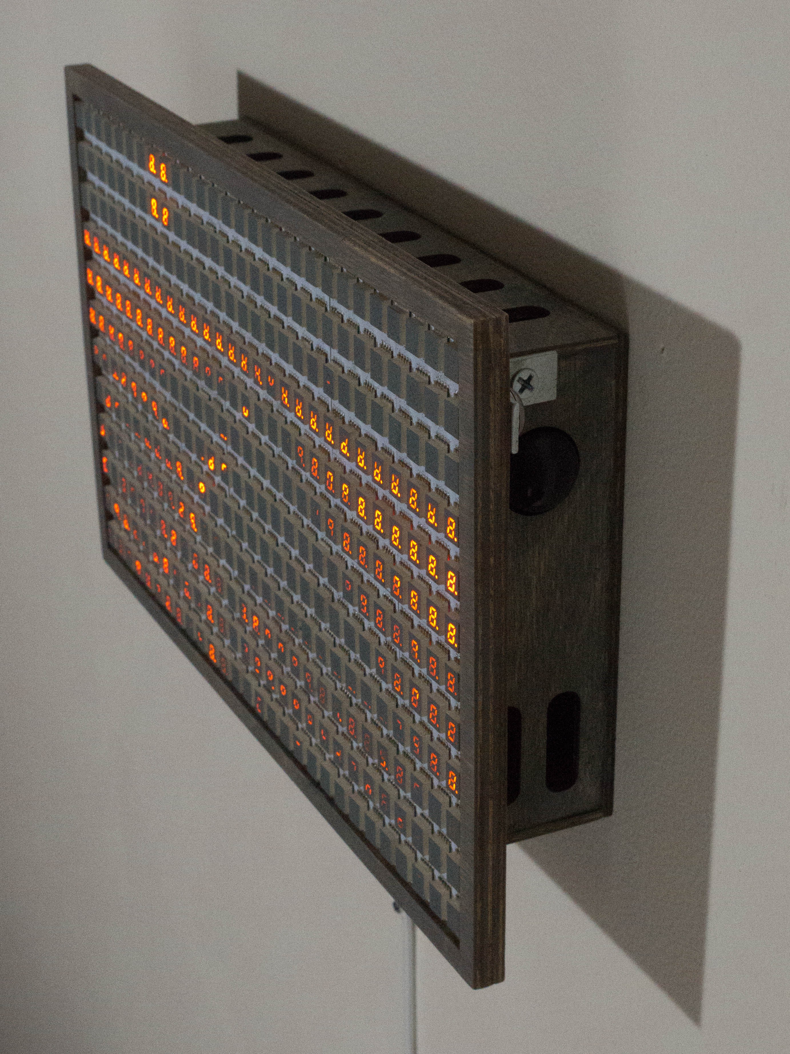
The prototype was fine but I felt that its enclosure was a little too nice and approachable. I felt that something about cold, hard numbers should probably feel like a cold, hard machine--ideally an ominous mainframe. So I revisited my favorite computing history reads, got some inspo from a few enclosure catalogs, and slowly pieced together a way of fitting it into a powder-coated steel frame.
I should mention at this point--I live in a 1-bedroom condo with my extremely patient s.o. and don't really have a garage-type space for doing big fun machining tasks or extra-stanky painting methods. So that takes out a lot of my enclosure-related options.
Luckily for me, Hammond's product line includes a 12x8x3" black powder-coated steel case that seemed extremely promising. I ordered one, along with its perfectly-fitting front panel, with the idea of machining either the case or the panel with cut-outs for the sensors and screen.
The opening on the front of the case ended up being an EXACT fit--down to the MILLIMETER--for the assembled panel. I mean this in a bad way--I could barely fit it inside! Don't skip your tolerances when reading those fancy diagrams, folks, lest you repeat this artist's near-mistake.
I ended up cajoling the panels to fit. I used a center punch and drill press (ok I do have one of those in the basement, heh heh) to get nice clean starts for each of the 12-24mm round cutouts required. Then I inished them with a step bit in a handheld drill. That plus some filing/reaming/judicious X-actoing let me clean up the holes well enough. Just one last piece of the puzzle--how to trim everything up?
Acrylic! I ordered three different degrees of smoked acrylic from good ol' Inventables and headed down to the (now back in commission) laser cutter at the DC Public Library. I cut a front panel, tapped the screw holes provided by Hammond, and cut out a few extra trim pieces from black acrylic. A small army of 50mm standoffs plus these acrylic trim pieces let me frame the display neatly inside the front of the enclosure, leaving plenty of room for the sensors and Pi, which I neatly adhered into the enclosure. The front smoked acrylic panel worked out very well. I didn't end up using the Hammond steel panel at all--guess it'll find its way into another project.
before:
after:
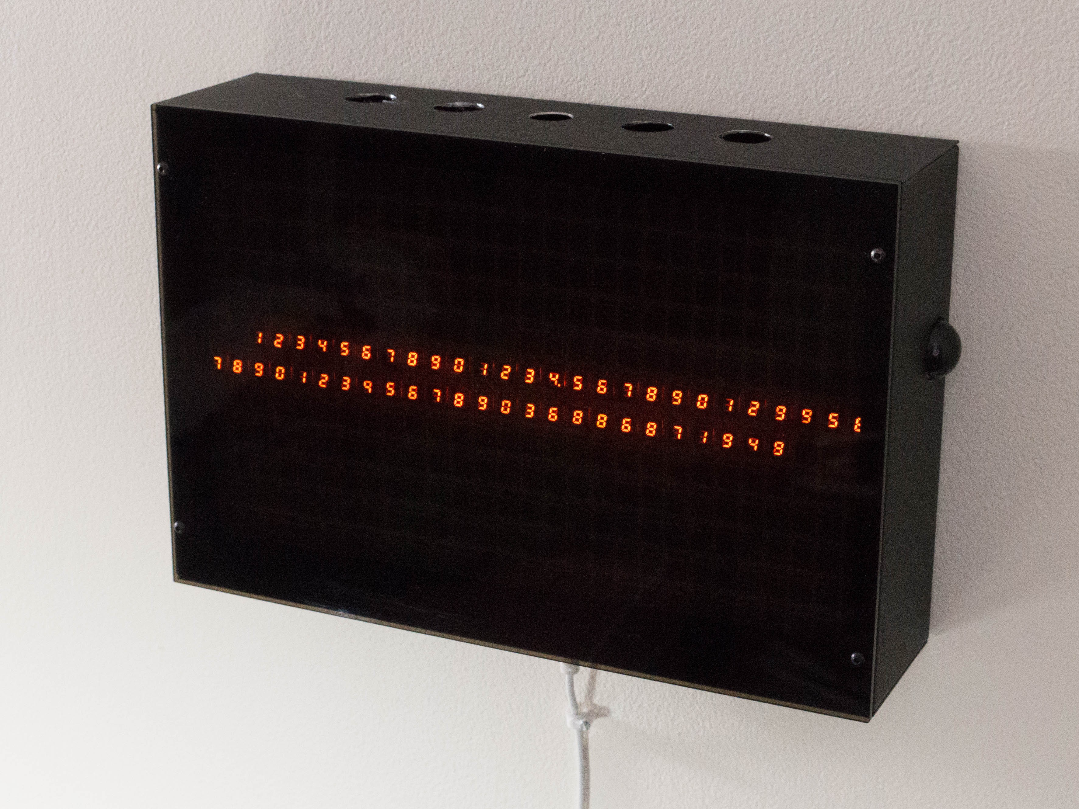
The only remaining wrinkle was figuring out how to photograph the piece with an extremely glossy front panel. Taking over the condo for a few hours, killing all the lights, and setting up at an oblique angle, I was able to get a few frames and videos.
And that's how this project ended up. Let me know if you have any questions or ideas. More of my work is at chriscombs.net, instagram, facebook. Thank you for checking out this build log!
-
Software and prototype: 2018-06
12/31/2019 at 22:18 • 0 commentsI had been working on the artwork behavior, assets, and software in parallel with the hardware. The overall architecture that I ended up with is this:
- Cython language--it's Python with a little extra static typing that is compiled as C, for dramatically faster performance in many cases
- Multiprocess architecture. By splitting blocking tasks into different processes I could arrange for much higher overall framerate
- The Python-IS31FL3733 driver (GitHub) is fairly primitive and performs best updating an entire display at once.
- Key processes:
- Launcher that monitors individual processes and restarts them if they die. It handles logging, pyximport (Cython magic), provides a message bus via Multiprocessing Queue and Pipe interfaces, and handles overall process control for graceful shutdowns
- Main application process, RoadAhead.
- Children: Renderers. At any given moment there are two renderers active out of an overall selection of 6 or so. They each render into a Pygame surface. The application process switches renderers, and alpha-blends the two active renderers together based on an overall "temperature" variable
- Pipe in: Render request
- Queue in/out: System bus
- SurfaceToRad renderer. Turns Pygame surfaces into the raw byte list (16x12 8-bit) required by Python-IS31FL3733.
- Pipe out: RadDisplay
- RadDisplay process. Initializes Python-IS31FL3733 i2c drivers for each display, restarts each if connection is lost. Emits "Render" requests as each frame is rendered. Maintains a 10-frame buffer (yes this is long, the artwork's responses to sensors are not intended to be that fast/readily triggerable. Think of it as a skittish cat. It will do what it wants on its own time and you are not intended to be able to directly control it)
- Pipe in: SurfaceToRad
- Pipe out: Render request
- Queue out/out: System bus
- RadGpio. Monitor select pins for GPIO events triggered by PIR and RCWL-0516 microwave sensors. Emit system bus events when they occur.
- Queue out/out: System bus
- Not a process exactly, but I needed to develop each of these components before the hardware was ready, so there is also a Pygame "simulator" environment that runs on my banged-up Ubuntu-powered Dell Latitude. (Best $150 I ever spent.) It deteects
One interesting problem was transforming these 7-segment displays into a general purpose pixel display. Under the hood the artwork considers itself to have a full pixel surface available at its disposal. It samples select pixels, calculated to match the physical position of each LED segment, and averages 2x2 pixel bins to get the desired grayscale value for each LED segment. This is somewhat computationally expensive, which is part of why I derived some benefit from pushing that into its own process (SurfaceToRad) on the multi-core Pi 3.
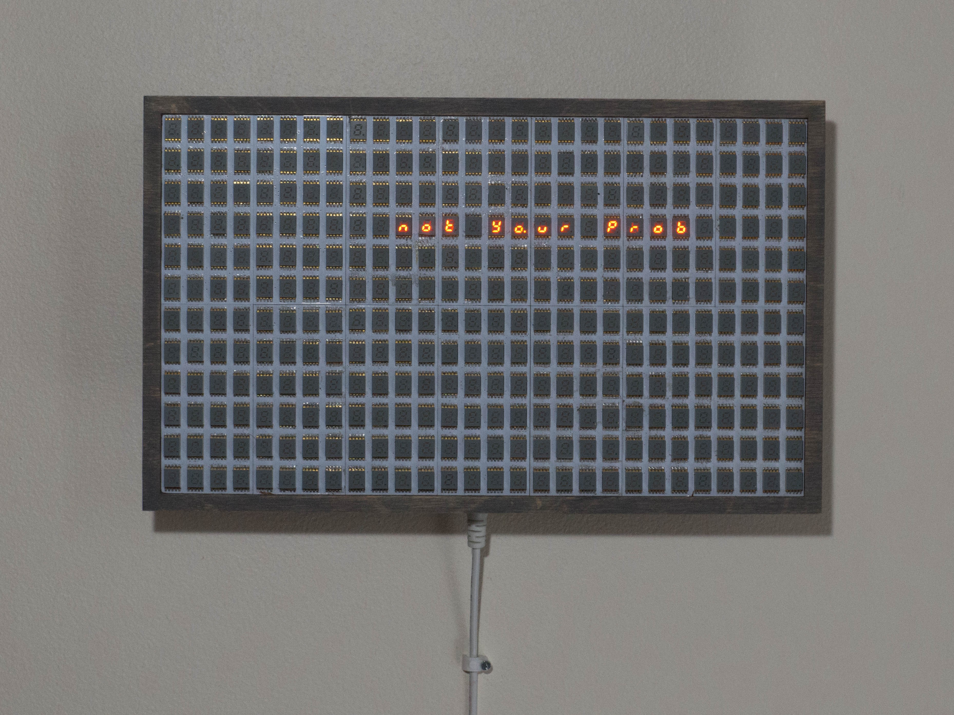
So once I went to all that effort to make a 7-segment display into a graphic display... then I wanted to show numeric digits back on the display. That's part of the fun to me, to have these numbers suddenly morph into a graphic display after you've been watching the numbers for a few moments--ideally in a mini galaxy brain moment (hey, gotta aim big). I ended up just working backwards from the SurfaceToRad logic: identify the pixels that will be used later as "ingredients" for each segment's brightness, then set each of those pixels to the desired brightness.
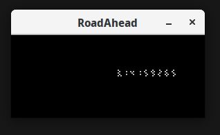
Here's what that looks like in the simulator.
You might be wondering by now: what exactly does this artwork do and why does it do it? It's risky to go too far down the road of explaining your own art--risky because you run the risk of constraining how your viewers will perceive and interact with the work. So bear with me for a moment if this explanation doesn't line up with your take:
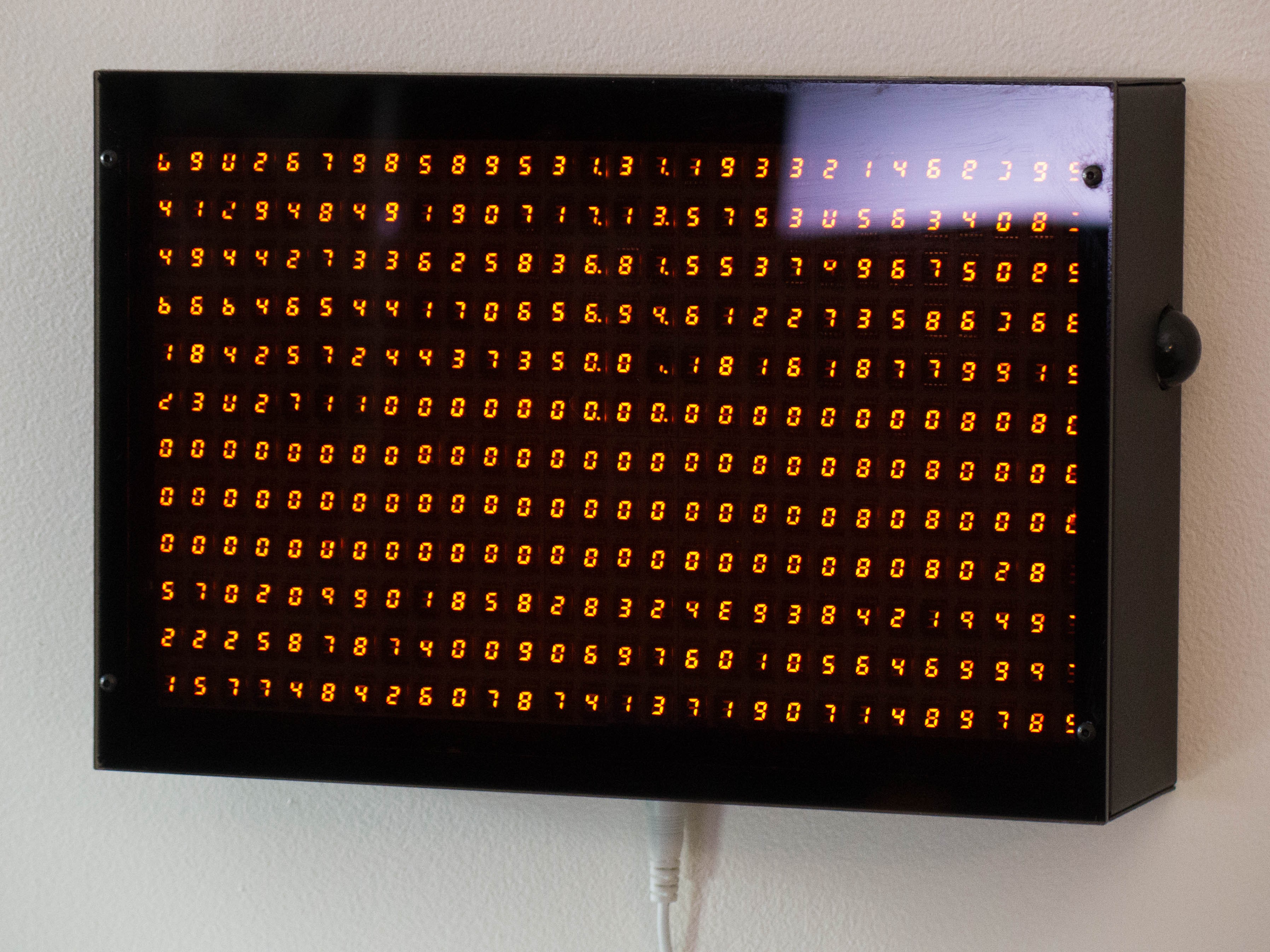
I am interested in how huge numbers of people are reduced to abstract numbers, often for the purpose of communicating about them in detached, alienating ways.
I thought it would be interesting to flip that dynamic--personal becoming impersonal through numbers--and use numbers as ingredients in a more personal or evocative visual display.
First, it starts by just showing you numbers, some meaningful, some meaningless. They are shown in a variety of ways, including some that appear like sums or subtraction, some reports, some dramatic single figures, some streams of endless digits.
Then the scene that you see once the artwork decides you're ready (by sensing enough motion) is an endless road (my homage to a certain bus-themed video game). As it senses movement to either side of the piece, hitchhikers appear in this landscape, but you never stop to pick them up. It will eventually fade back to the number-based displays.
Direct? no. controllable, puppet-style? no. but hey, that's what makes art fun to think about--making it chewy by layering all this extra stuff into it. imho, of course :)
Once I had the panels together I was really itching to get a prototype version of it out where I could gauge how people were interacting with it.
The artwork has several motion sensors in it, which guide the overall "temperature" variable, used to determine which view is shown. I felt that I couldn't really tune the sensor/temperature response until I could better see how patient casual viewers would be.
So speaking of galaxy brain, I had my own such moment when I realized that I had designed a 5v i2c system and utterly failed to account for how a 3v3 Raspberry Pi would communicate with it.
I had about two days before this totally great open-hang art gallery event--"1460 Wall Mountables" at the DC Art Center (you show up with $20 or so and can literally hang anything you want--one year I hung a horseshoe crab shell and sold it for $40). I was dyyyying to hang this artwork in the show. And of course my available inventory of level converters was 0 units. So, here's the dumb fix I came up with:
Use an XL6009 to bring the panel supply voltage of 5v down to 4v. Then it'll detect the ~3v signals from the Pi as high!
Added advantage of reducing system heat emission, and because the is31fl3733 is current-controlled, I don't think I lost any brightness from doing this.
I needed an enclosure. The DC Public Library has a laser cutter available, but it wasn't available right then because the library was being renovated. So I hit up (now sadly defunct) makerspace Catylator in Silver Spring and lasered me some 3mm plywood.
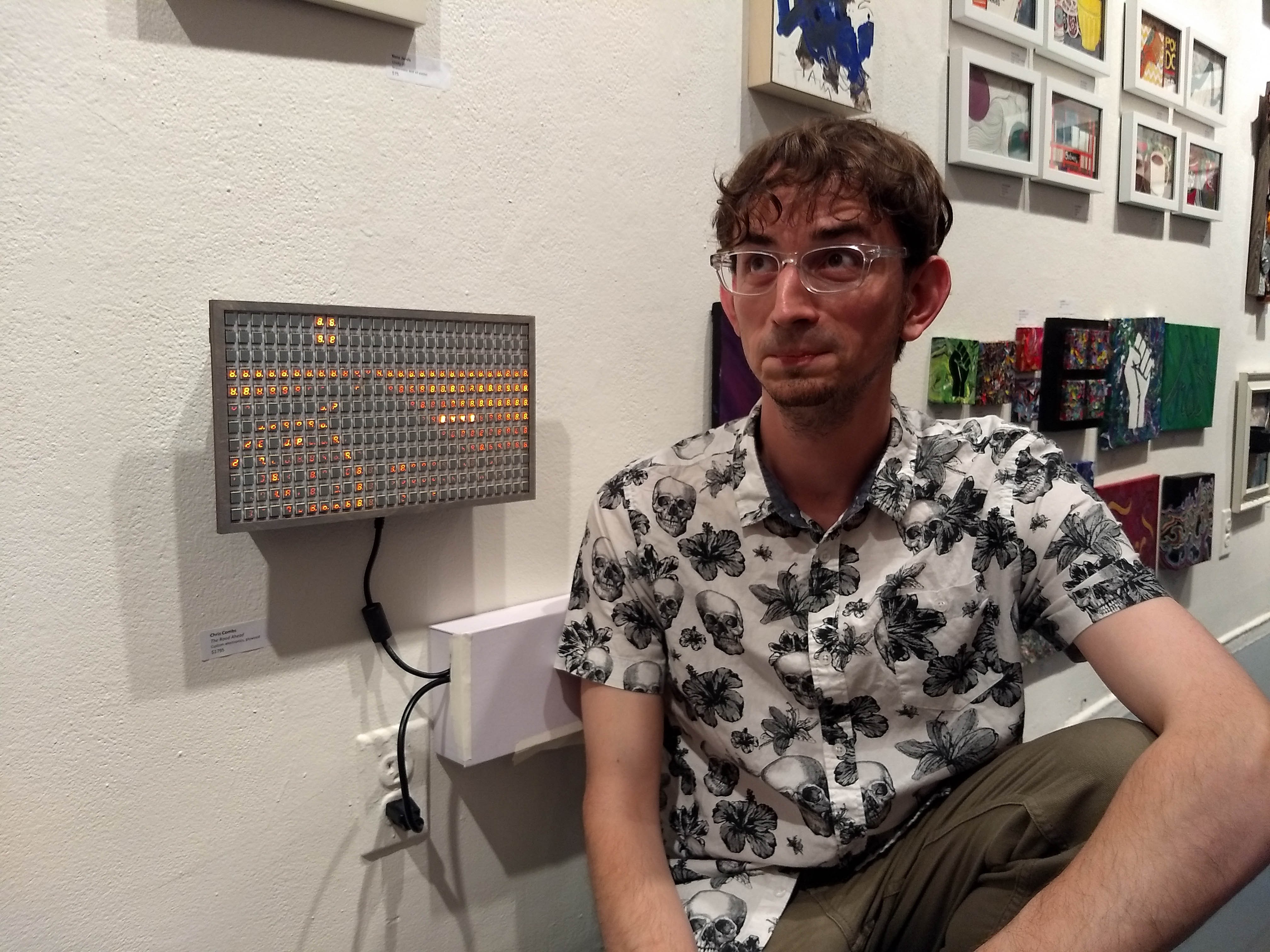
A bit of gray stain later, some bibs and bobs, and voila, prototype version (pardon my ridiculous face, someday I'll learn):
-
Building the panels: 2018-06
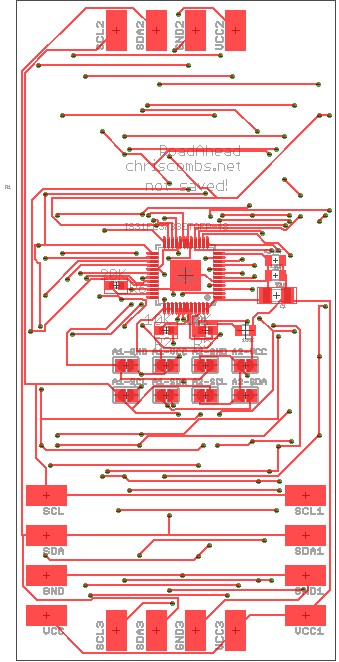
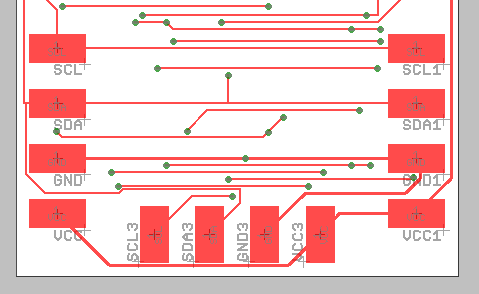
12/31/2019 at 21:36 • 0 commentsOnce I got the early 4-display test PCBs from OSH Park, the pieces started falling into place.
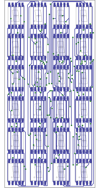
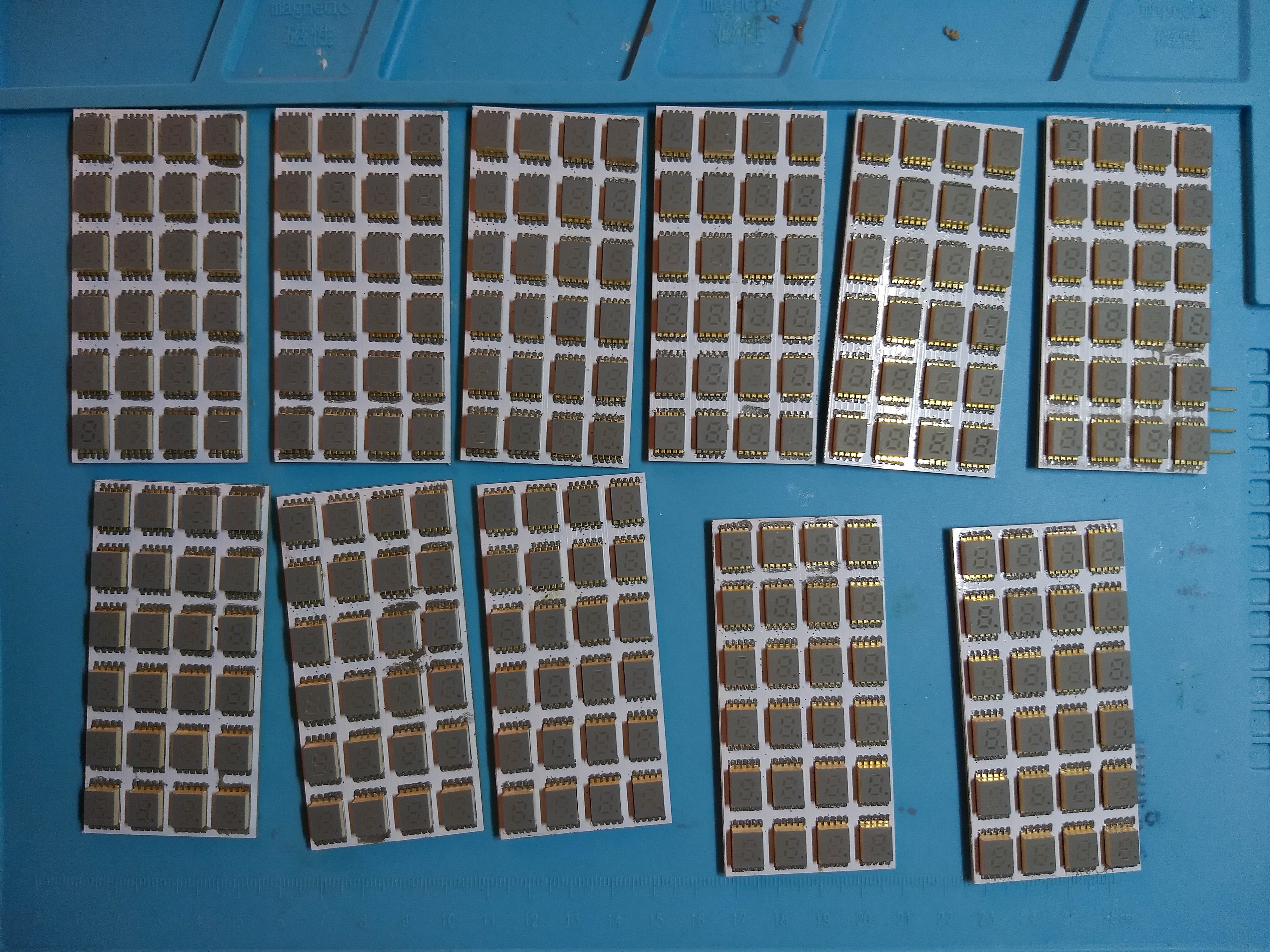
I was able to buy about 380 display modules. Each display controller could handle 16x12 segments, which I could arrange into 6x4 7-segment (really 8 w/ the dot) panels. 14 of these was 336 modules, leaving me room to spare for failures. And thanks to the chip's versatile use of address pins, I could easily fit them all on to the same bus.
I put together a full 6x4 module PCB, sent it off, and almost immediately realized that I had made a crucial mistake. (Insert forehead slap emoji here.) In the process of renaming some pins I had forgotten to hook up one of the address lines! I ordered some more from Elecrow via DHL and began bodge-wiring up a few boards.
(Yes, I use autorouters. As an artist, I like the strange, synthetic appearance, and it lets me work much more quickly. I do hand-route differential pairs.)
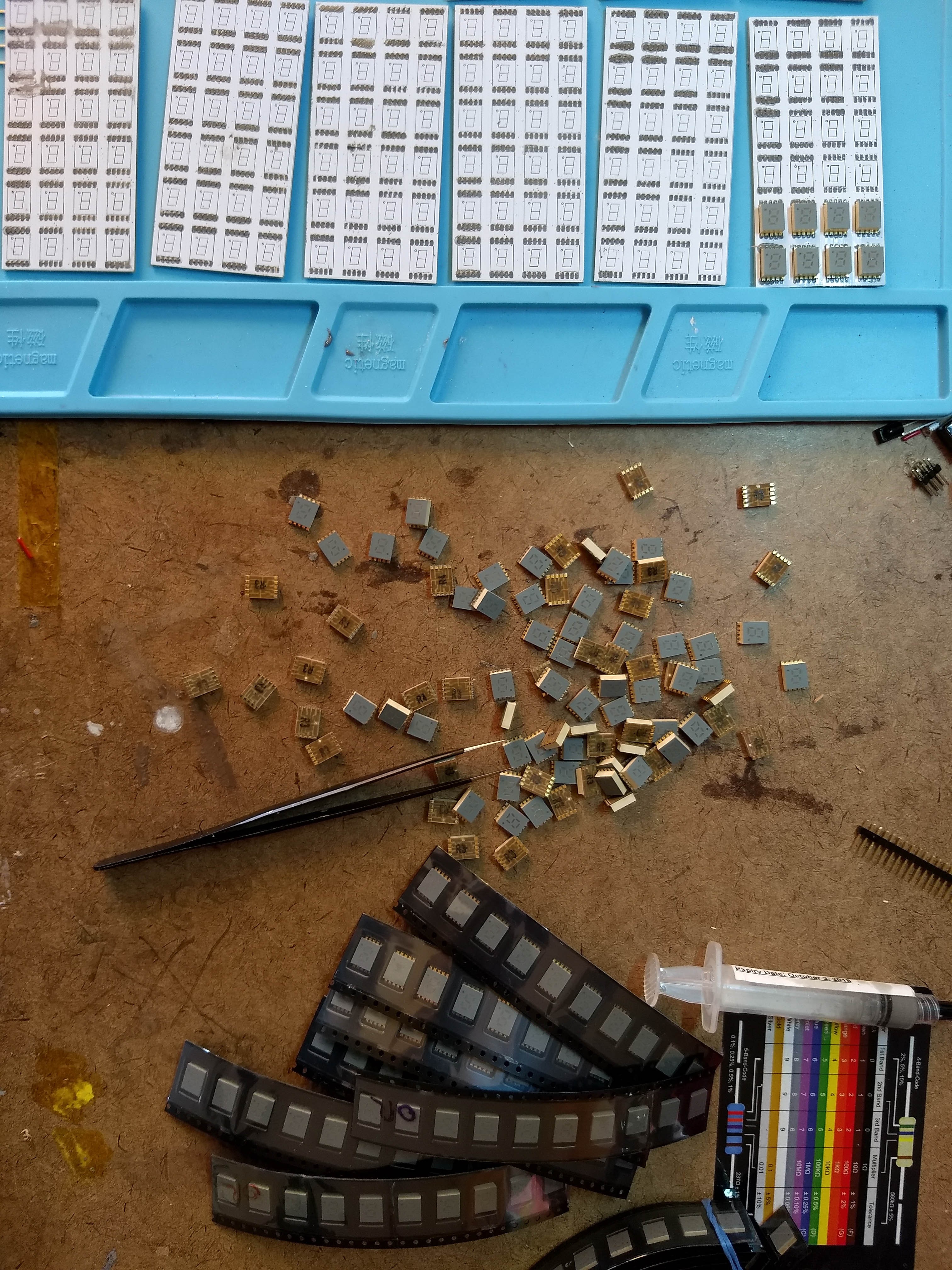
Just as well, ordering another round of boards gave me time to get a stencil and learn how to properly paste my boards (bad examples visible below).
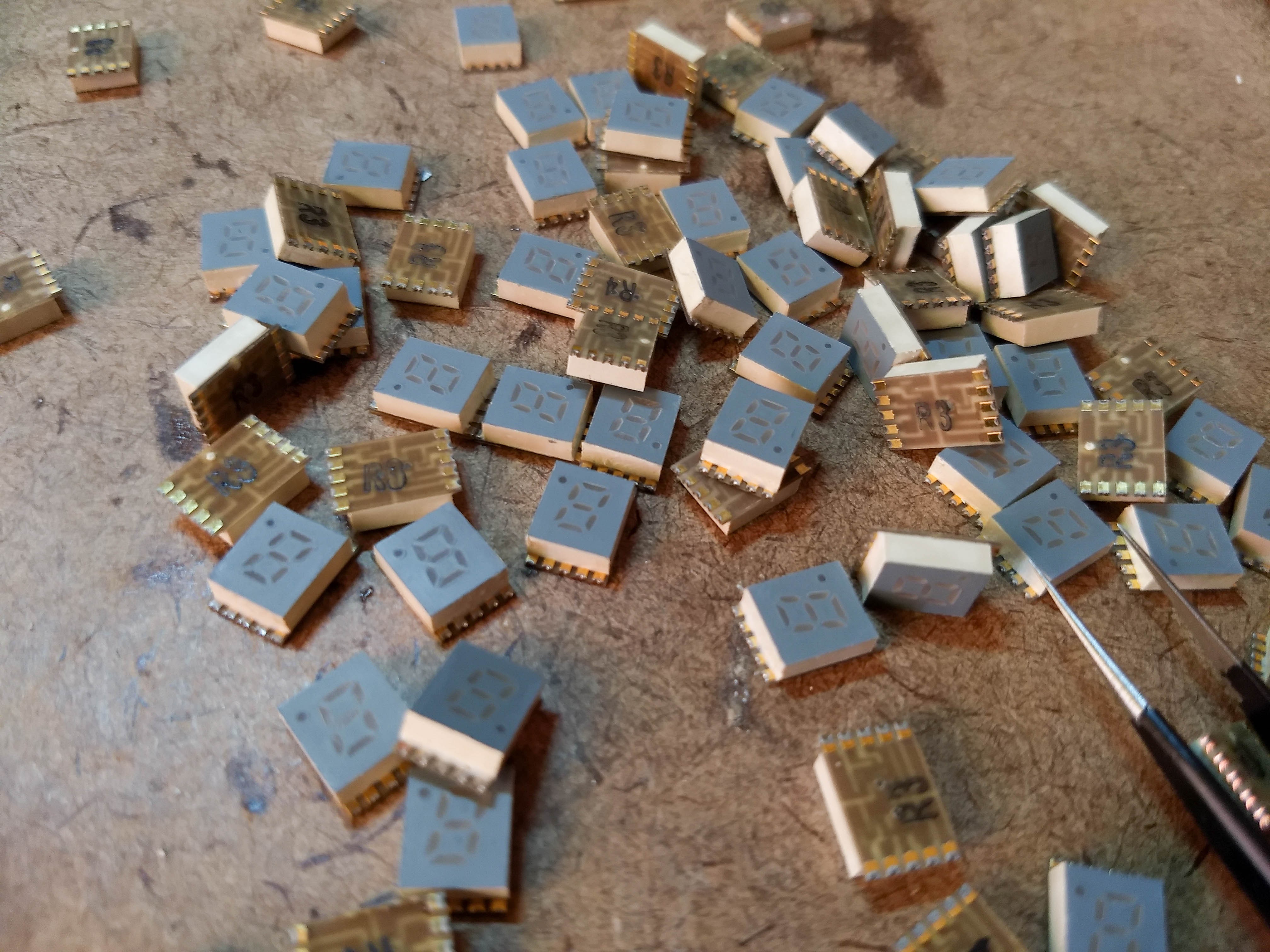
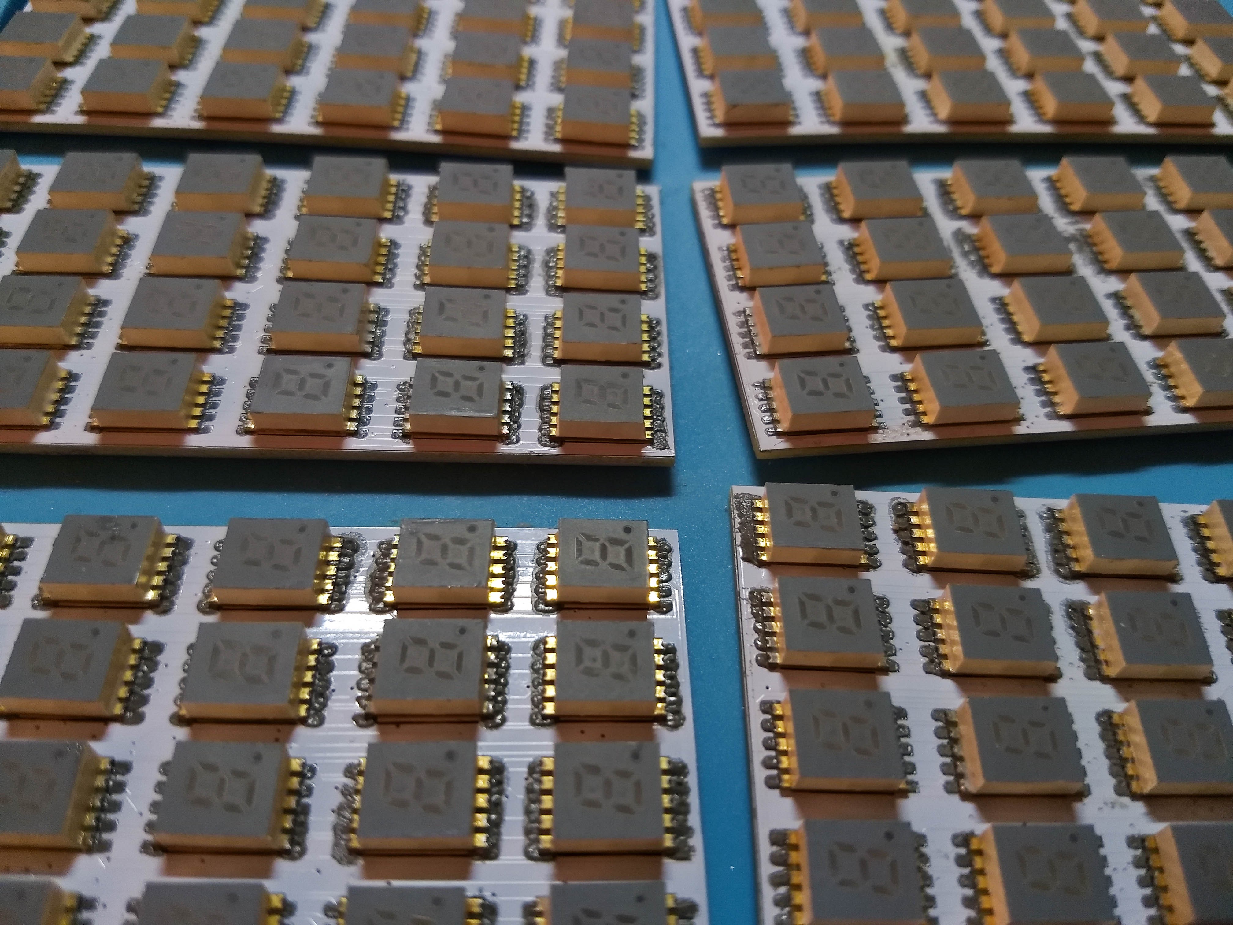
Here are some views of the assembly process:
Attaching the panels together turned out to be a bit of a challenge. I had in mind that I would solve the mechanical attachment stuff with some magic powder later in the process. Lesson learned, always make sure you have some kind of mounting points, even teensy... and don't half-butt your connectors.
I ended up taking pins from 0.1" header, finding the most flat surface in our condo, and laying them flat across the board-edge connector pads to connect the boards together:
(I'll grab a picture of the final connected versions next time I have it open.)
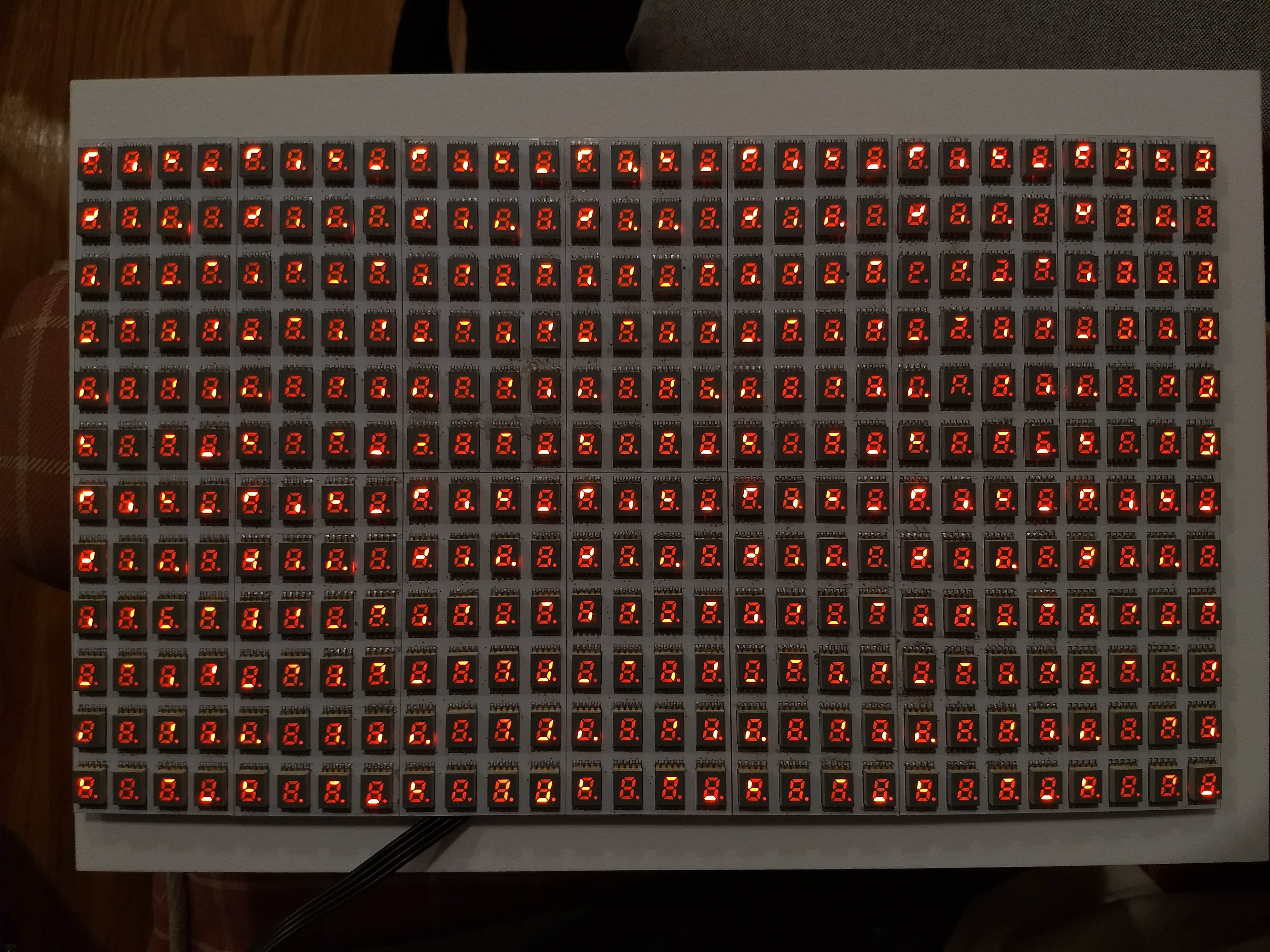
and before I knew it... first light!
-
Early days... 2017-06 to 2018-05
12/31/2019 at 18:58 • 0 commentsHow I got started on this project:
After finding a few 0.2" SMD LED 7-segment displays on Sites of Dubious Provenance, I got excited about using many of them to build a pixel display (given enough squinting).
There were a bunch available in blue for a fairly steep price. I ordered a few of these and fell in love with their appearance, and set up an eBay saved search to see if others would become available.
I cast about for a way to make a huge array of them. At first I started speccing out a solution with lots and lots of shift registers... That was not particularly appealing to me, especially given that the boards would probably be double-sided, so there'd be all this silicon on one side and all the displays on the other? I was doing all of my surface-mount soldering on a rework station, so double-sided stuff was tricky/bad. (Or if I kept everything on one side, I'd need to space out the LEDs to fit in all the chips, which would make it harder to perceive the "pixel" displays and make the boards larger, driving up costs.)
So I somewhat reluctantly decided to seek out more integrated controllers.
I looked at some existing commercial LED matrix modules available for sale on the finer maker-type webstores. I noticed that one was using IS31FL3731 in a "Charlieplexing" arrangement. That got me excited, since it would accept data over i2c and only require connecting the LEDs properly. Big drawback, though, Charlieplexing makes my brain hurt.
This might be a sort of noobish way to find parts, but I started googling for the same part number, wiggled by one. IS31FL3732 was much better, an 8x8 matrix array without any Charlieplexing required. (Take that, Chaz.)
But I felt that I really hit the jackpot with IS31FL3733. This is a 12x16 matrix array, no Chaz, I2C, with full 8-bit pwm per pixel.
I read through the datasheet, thinking about how it could work. Earlier I had looked into software, came up pretty dry. I poked around at aforementioned Maker Webstore's offerings and it seemed fairly straightforward to write an i2c driver in userspace Python. Was it possible for me to come up with some kind of driver on my end?
Spoiler alert, YES, and I was able to whip together a simple Python library that updated the entire display memory of the device. Some back-of-the-envelope math suggested I could hit my targets of 20fps for all of the panels on one 2MHz i2c bus.
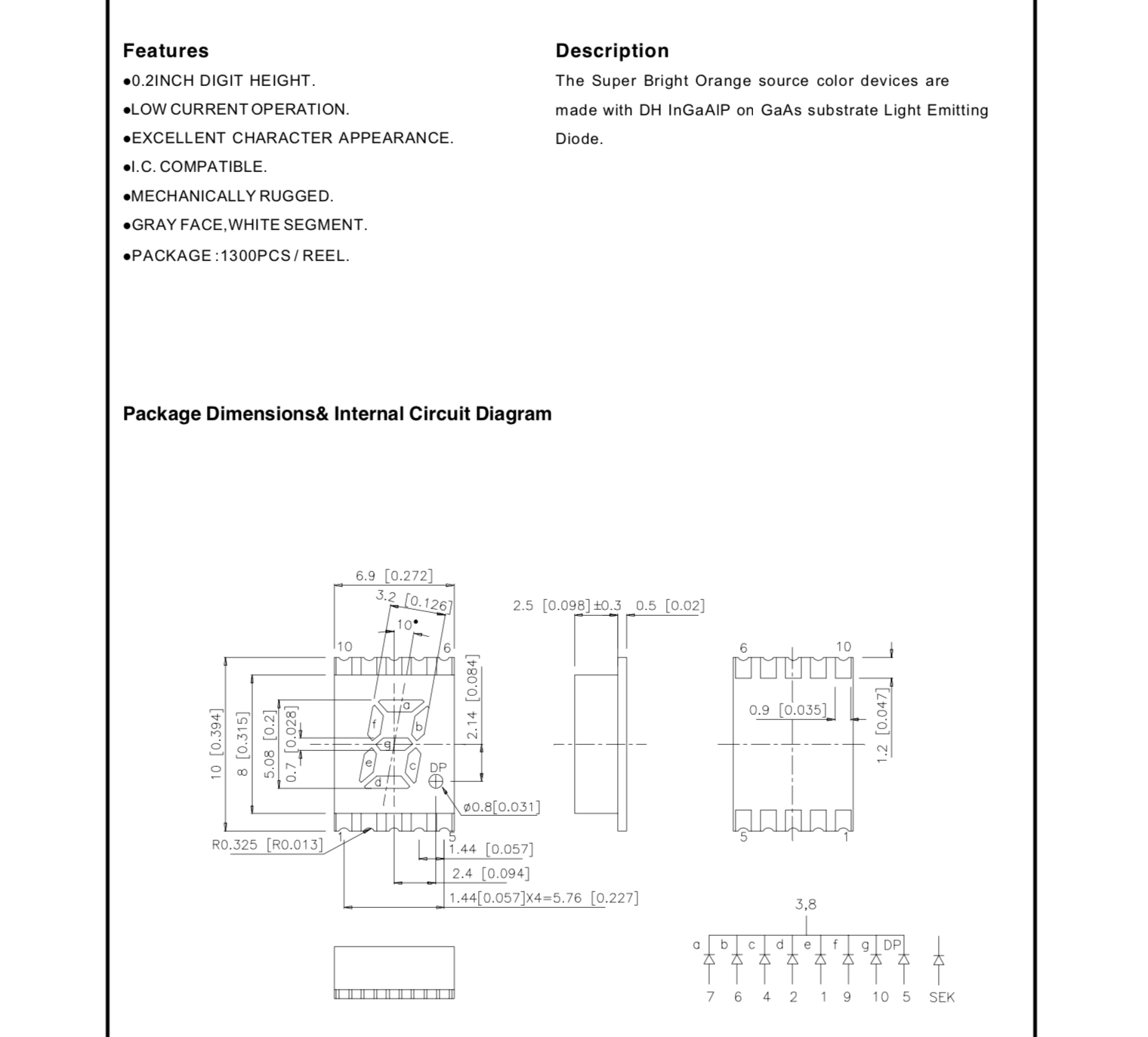
Around this time, a massive lot of amber/orange 0.2" Kingbright 7-segment SMD displays (APSC02-41SEKWA) showed up on eBay. I negotiated with the seller and landed a huge lot for a little more than I meant to spend (oops).
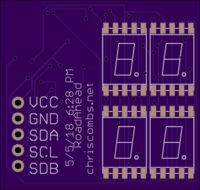
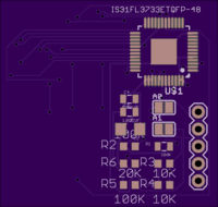
I worked up a crappy little 4-display board to try out the IS31FL3733 (forgive my terrible component placement, routing, silkscreen, etc.), signing myself up to write some kind of driver--that'd be a problem for Future Chris.
The TQFP version of this part is only available to my U.S. location via Mouser, so I placed an order, hit up OSH Park, and crossed my fingers.
336-digit 7-segment display with per-segment PWM
Using 14 panels with ISSI IS31FL3733 I2C matrix controllers, this artwork can show 8-bit grayscale on 2,688 individual LED segments.