John Anderson
-
Check out the new digital dice tower project
08/19/2022 at 04:47 • 0 commentsI am closing this project and have already created a new one capturing all of my dice tower designs. The new project also has a series of detailed blog posts describing step by step how to build the most recent dice tower design based on the very attainable Bell & Howell IMD202 digital multimeter. It also includes the project/source files and binary images for the firmware. So I encourage you to check it out and "follow". You can see the new project here: Resto-Mod Audible Digital Dice Towers
BTW, the new project is a finalist for the Supplyframe DesignLab: 2022 Hackaday Prize.
-
More HD-16 based Digital Dice Towers
06/28/2022 at 08:19 • 0 commentsHere's a few more Digital Dice Towers based on the Heathkit HD-16 case and original speaker. These demonstrate a variety of display options.
-
Digital dice tower in a new form factor
06/28/2022 at 07:49 • 0 commentsUsing the decoder/drivers and nixies from one of the Bell & Howell digital multi-meters, the same micro-controller with software, and a cheap 170v dc to dc power supply kit from Ebay, I built a yet another dice tower in a new form factor. This one is based on an old Heathkit HD-16. The HD-16 was a kit available in the late 60's and early 70's. It was used by HAM radio operators to practice morse code.
-
Yet another revision...
02/10/2021 at 10:04 • 0 comments -
New features in the new project...
02/10/2020 at 19:33 • 0 commentsI've posted an updated video of the new features in the latest Digital Dice Tower I built. It's based on the same Bell & Howell Digital Multi-meter.
You can learn more about these features in the new project; 1979 Heathkit D&D Digital Dice Tower
-
That's a wrap
01/23/2020 at 22:17 • 0 commentsThis project has been completed. If you are interested to read about additional features I am adding with subsequent builds of this concept, like and follow the latest project: 1979 "Heathkit" D&D Digital Dice Tower
-
The final details...
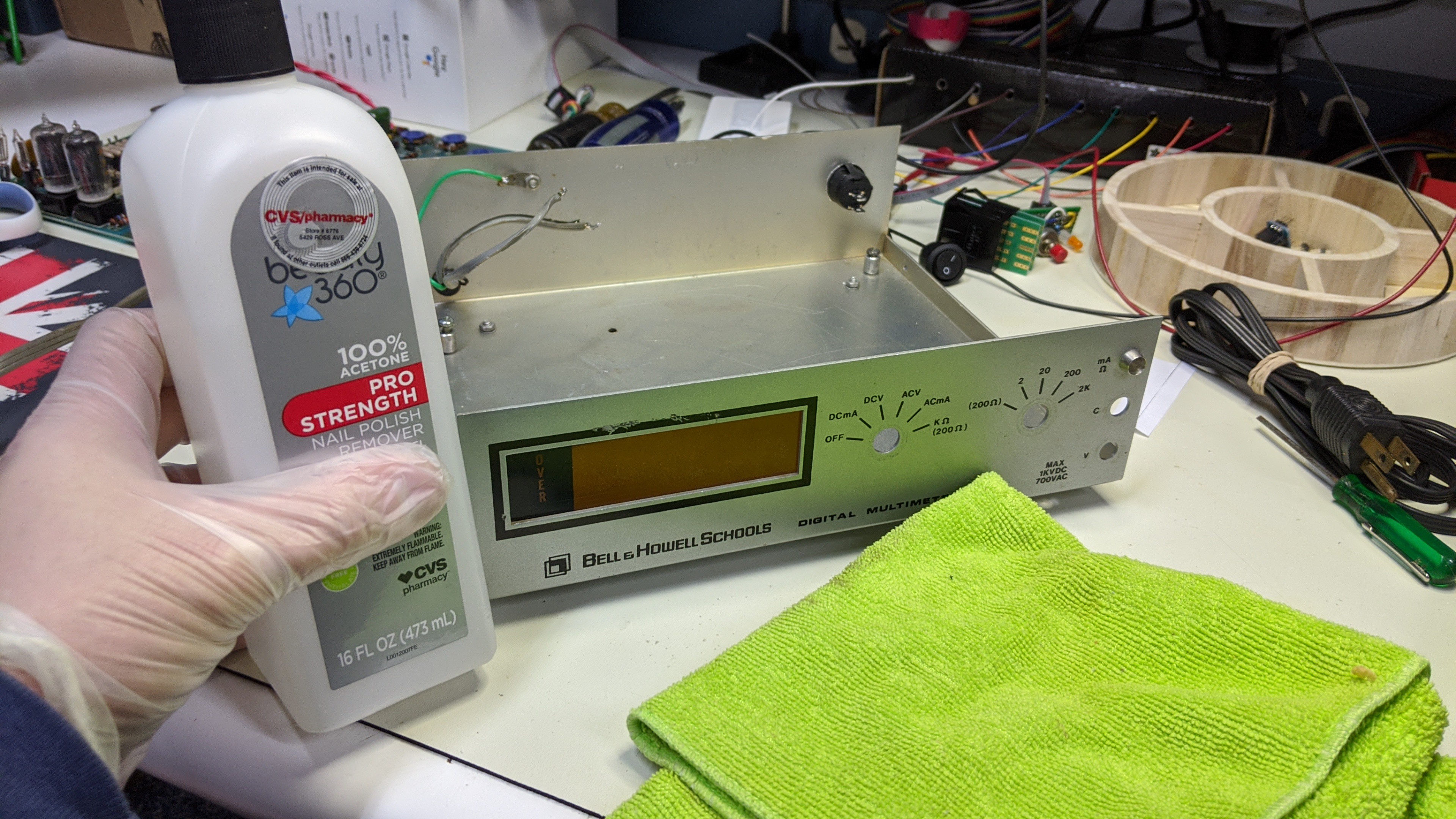
01/23/2020 at 07:22 • 0 commentsNow that the case has been modified, a controller board has been wired up and connected to the power supply / nixies, new switches installed, and code loaded and debugged. The only thing remaining is to update the graphics on the faceplate to match the functions of the new switches and button.
This starts with removing the old graphics. 100% acetone and a rag is all you need to do that. Simply soak some acetone into the rag and rub the graphics you wish to remove. It takes a few minutes of wiping to get each section clean. Avoid getting acetone on any graphics you wish to keep. In my case, I left the graphic "bezel" around the nixie display window.
![]()
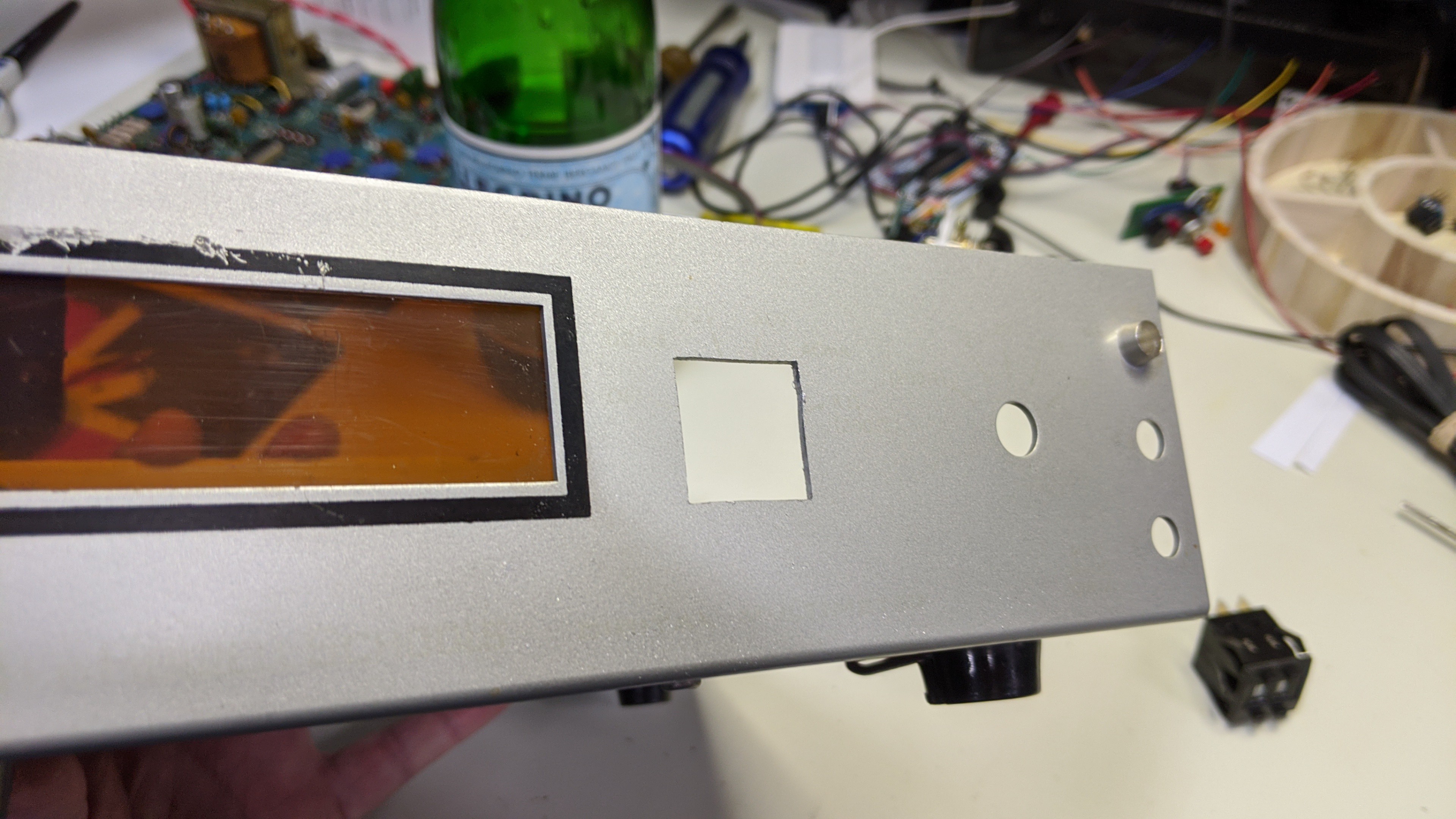
When you're done the base silver paint will still be there but the black lettering will come off completely.
![]()
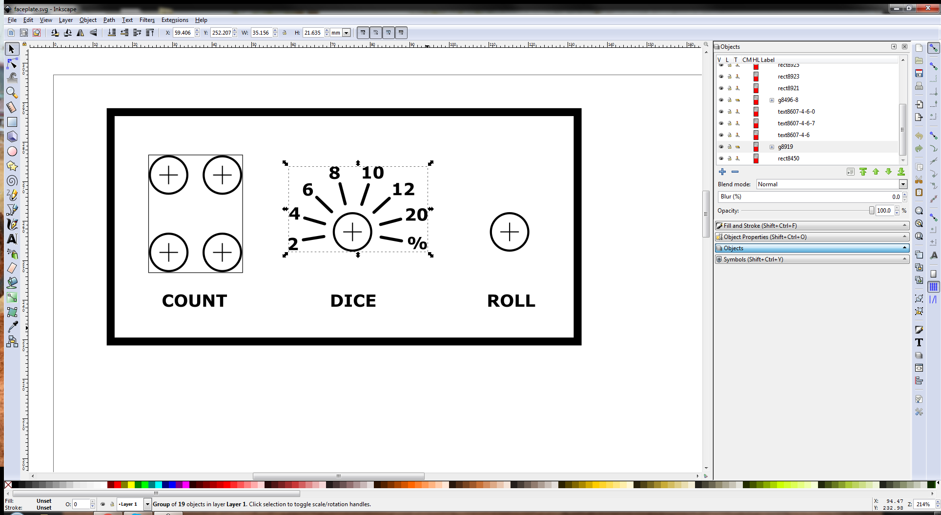
As shown in a previous log, I laid out a new set of graphics to scale using Inkscape in my PC.
![]()
I printed this to a water slide decal paper and transferred it to the faceplate before installing the switches.
![]()
The water slide decals were very easy to apply and look pretty good in the pics I've posted. But in person you can make out the outer edges of the transparent backing. So if you use it, trim it very close to the graphics and/or trim to align the edges of the decal with the edges of the faceplate. For my next revision of this hardware, I'll try some old school embossed labels for a 70's home-built look.
Speaking of the next revision of this hardware, I'll be wrapping up this project and marking it completed. I'll create a new project, "1979 Heathkit D&D Digital Dice Tower", to cover the next iteration. It'll be based on a the same Bell & Howell multi-meter, but it will have some new features, components, and software. So look for it and "follow" if you want to checkout some of the new features like sound/voice.
-
Just a Matter Of Software (JMOS technology)
01/22/2020 at 01:58 • 2 commentsThe last piece required to make all this old and new hardware useful is the software. The software for this application simply collects the input from the switches/buttons, determines the user's intent, and displays appropriate values on the nixie displays. The source for this application can be found in the main.c file attached to this project.
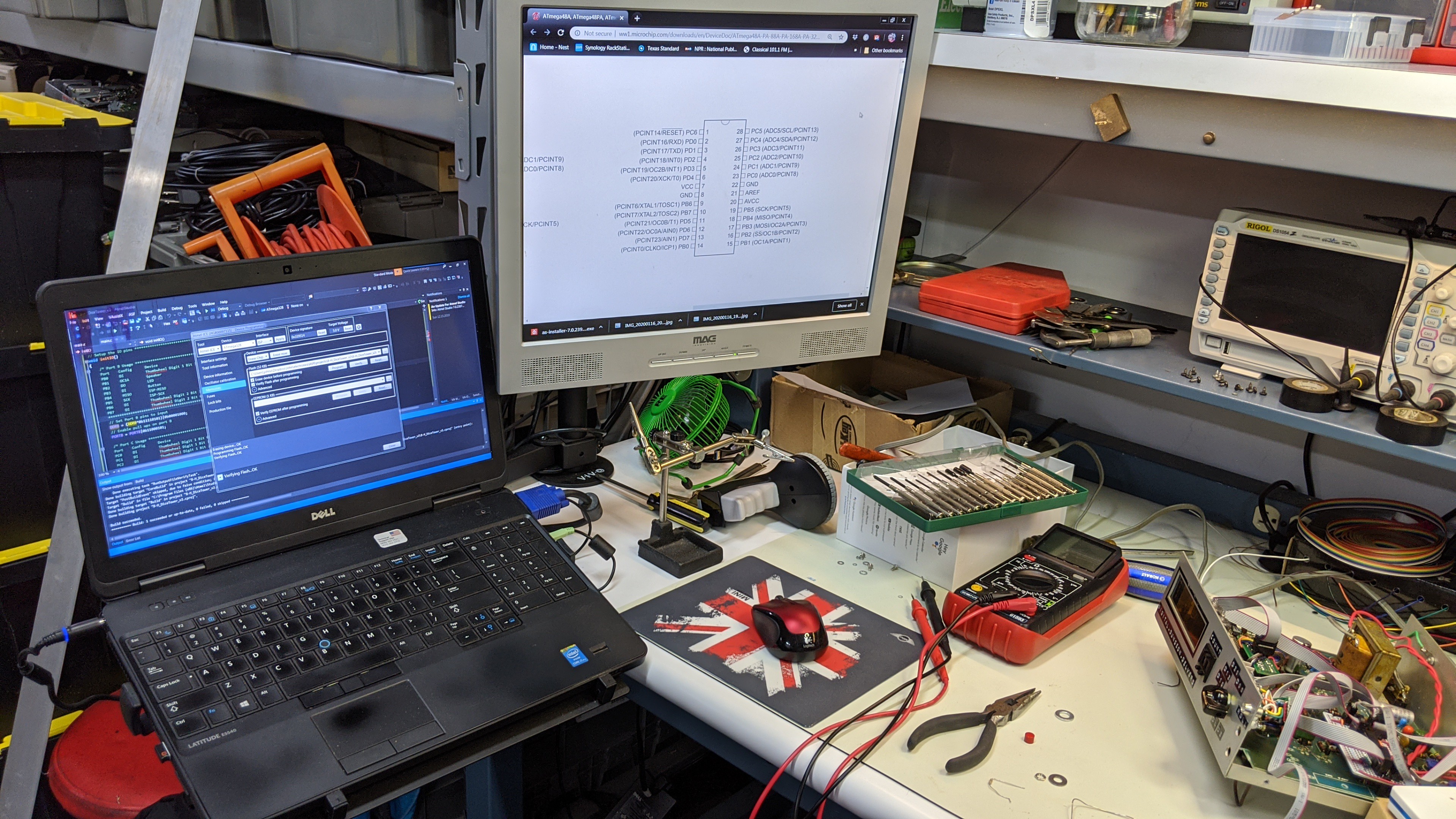
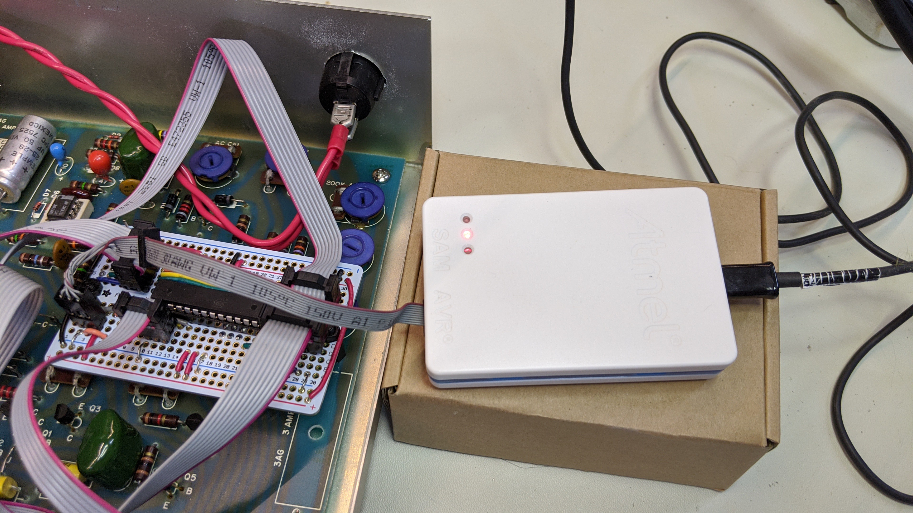
For code development, image loads, and debugging, I use Atmel Studio 7.0 running on an old Windows 7 laptop connected to an Atmel ICE via USB. I am very impressed with Atmel Studio's IDE, project management, editor, and JTAG interface. I haven't written code in 15-20 years and I learned how to use it to create projects, edit code, manage files in a project, load images to microcontroller flash, and debug (breakpoints, single step, set watch tables, etc) in no time flat without reading through loads of documentation. This is by far the best free software that I have ever used. My one ding on it is the lack of Linux support. But, I can live without that.
![]()
I'm also very impressed with the Atmel-ICE. I paid $90 for the basic kit and I got a full featured JTAG programmer/debugger that integrates with completely with Atmel Studio. It supports both AVR (ATtiny, ATmega, and ATxmega) and SAM ARM microcontrollers. And, it supports ISP, AVR JTAG, DebugWire, PDI, and SAM ARM JTAG. That's enough for years of projects I have in my queue. BTW, I have used a couple of the cheap AVR/Auduino USB ISP and JTAG programmers and they range from ok to non-functional. None of them provide the wealth of device/interface support the Atmel-ICE does. Or at least, I can't figure out if they do or not. Documentation is always sketchy at best.
![]()
The application program can be broken down into 3 parts; hardware initialization, hardware interface, and application state machine.
First is the hardware initialization. This is a single function that is called once in main() at start up. It sets up the I/O pins for the functions used by this application. In this case, port B pins 0-7 are connected to the 2 digit thumbwheel input, port C pins 0-2 are connected to the three outputs from the 74HC148 encoding the rotary switch setting, Port C pin 7 is connected to the momentary contact button, and Port D pins 0-7 are connected to the two 7441's driving the nixie displays. So the data direction registers and pull ups (enabled on all digital inputs) are configured as necessary.
// Setup the IO pins **********************************************************
void initIO()
{
    // Set Port B pins to input
    DDRB = 0b00000000;
    // Enable pull ups on port B
    PORTB = 0b11111111;

    // Set Port C pins to input
    DDRC = 0b00000000;
    // Enable pull ups on Port C
    PORTC = 0b11111111;

    // Set Port D pins to output
    DDRD = 0xff;
    PCICR = 0x00;
    PCMSK2 = 0x00;
    EIMSK = 0x00;

}
Note, there is some extra setup of the PCICR, PCMSK2, and EIMSK config registers. These represent the alternative functions for the port D pins. The code is setting them to their default cold boot values. So, they aren't necessary. They were added while debugging what turned out to be an unrelated problem. I never bothered to take them out.
The next part is the hardware interface functions. These functions read the status of the switches/button and output values to the nixie tubes.
The first function outputs the provided integer value to the two digit nixie display connected to Port D.
// Output a two digit decimal number on the Nixie Tube display ****************
void output(int out)
{
    int outputByte = out%10;
    out /= 10;
    outputByte |= (out%10)<<4;

    PORTD = outputByte;
}
The next function returns the current setting of the thumbwheel switch as an integer value.
// Get the dice count from the thumbwheel input *******************************
int getCount()
{
    uint8_t rawCount = ~PINB;

    // Bad wiring on both the thumbwheel and the board
    int count = (rawCount&0b00000011) | ((rawCount&0b00010000)>>2) | ((rawCount&0b00000100)<<1);
    count += (((rawCount&0b00100000)>>5) | ((rawCount&0b00001000)>>2) | ((rawCount&0b11000000)>>4)) * 10;

    return(count);
}
Note: There is a lot of bit twiddling going on here. I managed to accidentally flip two wires soldered to the thumbwheel switch and when I tried to "un-flip" them when I soldered the connector on the controller board I messed it up even more. So I fixed the hardware problem in code. Because that's yet another thing embedded software programmers do. They fix hardware problems :-)
Also, the value read from the port register is bit inverted. That's because the switch is wired with a common ground and each pin has a pull up enabled. The BCD encoding in the switch shorts the associated pins to common. So, for example, the values 1 and 2 on the thumbwheel switch will look like 0xec at the PINB register. Bit inverted that becomes 0x12.
The next function returns the selected dice type as an integer value representing the number of sides.
// Get the dice type **********************************************************
int getDice()
{
    uint8_t rawDice = (~PINC)&0x07;
    int     dice;

    switch(rawDice)
    {
        case 1:
            dice = 20;
            break;
        case 2:
            dice = 12;
            break;
        case 3:
            dice = 10;
            break;
        case 4:
            dice = 8;
            break;
        case 5:
            dice = 6;
            break;
        case 6:
            dice = 4;
            break;
        case 7:
            dice = 2;
            break;
        case 8:
            dice = 99;
            break;
        default:
            dice = 100;
    }
    return(dice);
}
The last hardware interface function returns the status of the push button. The status is returned as an integer that is 1 if the button is pressed and 0 if the button is not currently pressed.
// Get the status of the roll button ******************************************
uint8_t getButton()
{
    uint8_t ret = ((~PINC)&0b10000000)>>7;
    return(ret);
}
With these hardware functions in place, it's just a matter of creating a simple state machine that updates the nixie displays relative to the inputs from the user. That code resides completely in the main() function. The state machine implemented as in a switch statement with each case representing a state. It's simple and relatively easy to read for the a state machine this small.
// Program entry point ********************************************************
int main(void)
{
    unsigned int seed = 0, seeded = 0;
    int          i, count = 0, dice = 0, result = 0, timer = 0;
    State        state = State_Init;

    initIO();

    // Forever
    while (1)
    {
    // Increment the seend counter
    ++seed;

    // Implement the states of the application
    switch(state)
    {
        // Initialization
        case State_Init:
                count = getCount();
            dice = getDice();
            result = 0;
            timer = 0;
            state = State_Idle;
            break;
        // Idle
        case State_Idle:
            output(result);
            if(getDice() != dice)
            {
                timer = DISPLAY_BLANK_TIME;
            state = State_Update_Dice;
            }
            else if(getCount() != count)
            {
            timer = DISPLAY_BLANK_TIME;
            state = State_Update_Count;
            }
            else if(getButton())
            {
            timer = 10;
            state = State_Roll;
            }
            break;
        // Set the dice type to be rolled
        case State_Update_Dice:
            output(BLANK_OUTPUT);
            if(!--timer)
            {
            dice = getDice();
            timer = DISPLAY_CONFIG_TIME;
            result = 0;
            state = State_Display_Dice;
            }
            break;
        // Momentarily display the dice type
        case State_Display_Dice:
            if(dice == 100)
            output(99);
            else
            output(dice);
            if(getDice() != dice)
            {
            timer = DISPLAY_BLANK_TIME;
            state = State_Update_Dice;
            }
            else if(!--timer)
            state = State_Idle;
            break;
        // Set the number of dice to be rolled
        case State_Update_Count:
            output(BLANK_OUTPUT);
            if(!--timer)
            {
            count = getCount();
            timer = DISPLAY_CONFIG_TIME;
            result = 0;
            state = State_Display_Count;
            }
            break;
        // Momentarily display the dice count
        case State_Display_Count:
            output(count);
            if(getCount() != count)
            {
            timer = DISPLAY_BLANK_TIME;
            state = State_Update_Count;
            }
            else if(!--timer)
            state = State_Idle;
            break;
        // Simulate a roll by flashing random values of the dice type on the display
        case State_Roll:
            output((rand()%dice)+1);
            if(!--timer)
            state = State_Roll_Result;
            break;
        // Calculate and display the roll result
        case State_Roll_Result:
            // If not seeded...
            if(!seeded)
            {
            // Seed the rand() function with the seed counter
            // that has been incrementing since startup
            srand(seed);
            seeded = 1;
            }
            result = 0;
            for(i=0;i<count;++i)
            result+=(rand()%dice)+1;
            state = State_Idle;
            break;
        }
        // Insert delay based on the current state
        // Note: if init or idle state, no delay inserted and
        // The seed counter increments as fast as this loop spins.
        if(state==State_Roll)
            delay_ms(100);
        else if(state>State_Idle)
            delay_ms(1);
    }
}
I don't have a state diagram to share. But it's simple enough to read through in source code.
Basically this state machine sits in the idle state displaying the last result value on the nixie tubes. If it detects a new value on the thumbwheel or rotary switch it sets a timer count and goes to the appropriate "update" state for a 100 milliseconds, displays 00, updates the value, and then goes to the "display" state. In the "display" state it displays the recently selected value (count or type) on the nixies for 500 milliseconds, and returns to idle. Back in idle, if it detects the roll button pressed it will set the timer counter and go to the roll state. In the roll state, it flashes 10 values calculated using the rand() function and the type of dice selected. Each of these values are displayed for 100 milliseconds. After 10 values are flashed, it goes to the roll result state. In the result state it checks if the rand() function has been seeded. If not, it seeds the rand() function using the seed counter that has been incrementing since start up. The rand() function is only seeded once. After that, the result state calculates the die roll result using the dice type and count to calculate the result. The result is stored and the system returns to the idle state where the result value is displayed until the next user input.
-
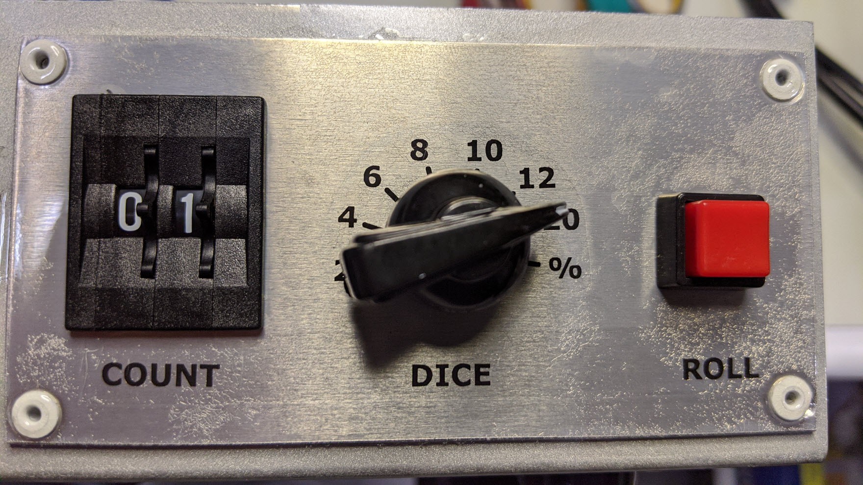
User Interface Circa 1978
01/21/2020 at 00:11 • 0 commentsTo keep this project looking the part, I selected input hardware technology that dates back to the period. This includes a panel mount momentary push button to roll the dice, a 8 way rotary switch to select the die type, and a 2 digit 10 position decimal thumbwheel switch to select the number of dice. I covered how these were physically installed into the case in a previous log. In this log, I'll describe how they were wired up to the AVR microcontroller.
![]()
The button is a simple connection to one of the AVR pins configured as an digital input with the pull up enabled. The other side of the switch is connected to a common ground with the AVR. It connects to the controller board via a keyed 2 pin single row IDC connector.
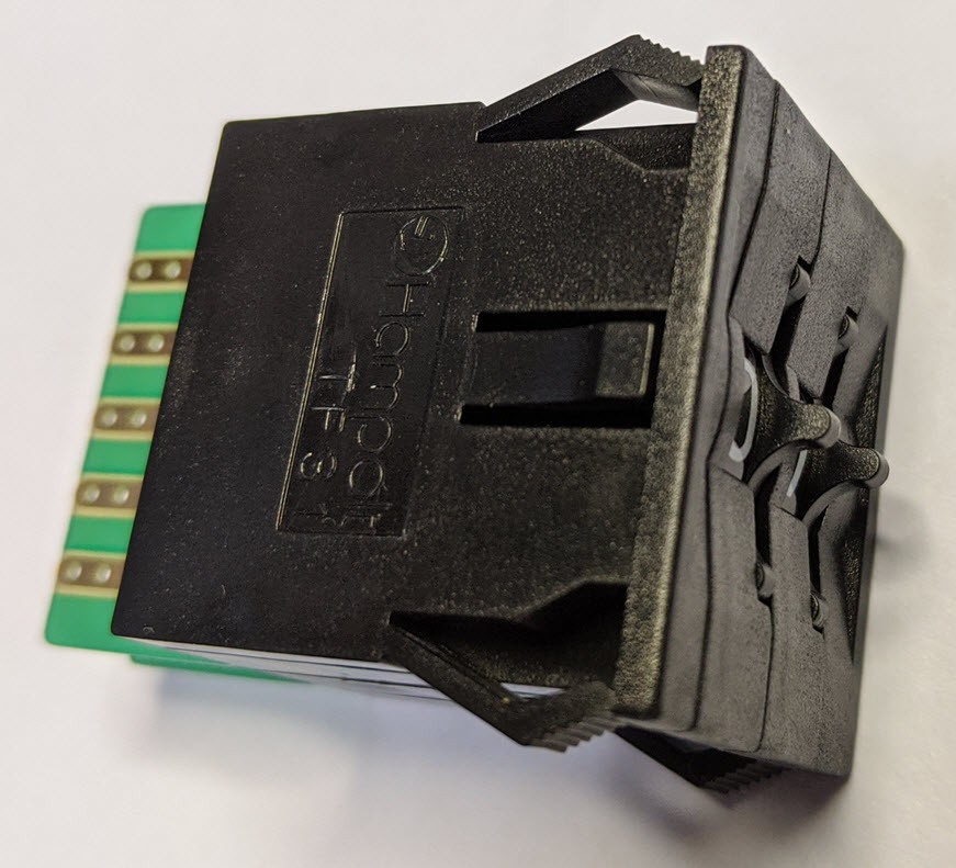
The 2 digit decimal thumbwheel switch is a Hampolt TF31 2-Digit Thumbwheel Switch (BCD encoded). These can be found on E-bay for a reasonable price. They ship from Taiwan so plan for a lead time of a week or two. If you substitute another thumbwheel switch, be sure to get a BCD encoded style switch to minimize the number of processor inputs or external logic IC's required. I soldered a short piece of multi-color 10 conductor flat ribbon cable directly to the pads and crimped on a 10 pin dual row female IDC connector on the other end to connect to the controller board. Like the button, the 8 AVR pins are configured as digital inputs with the pull-ups enabled. The cable to the switch includes ground which is connected to the common pad on both digits.
![]()
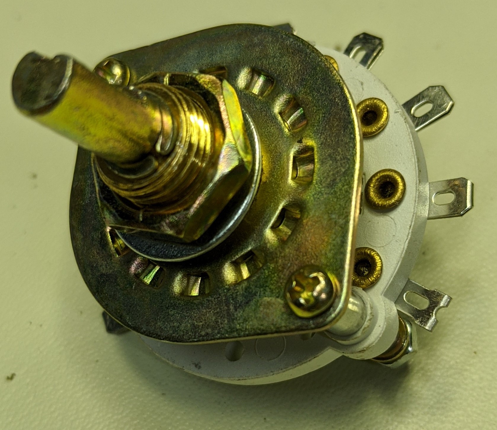
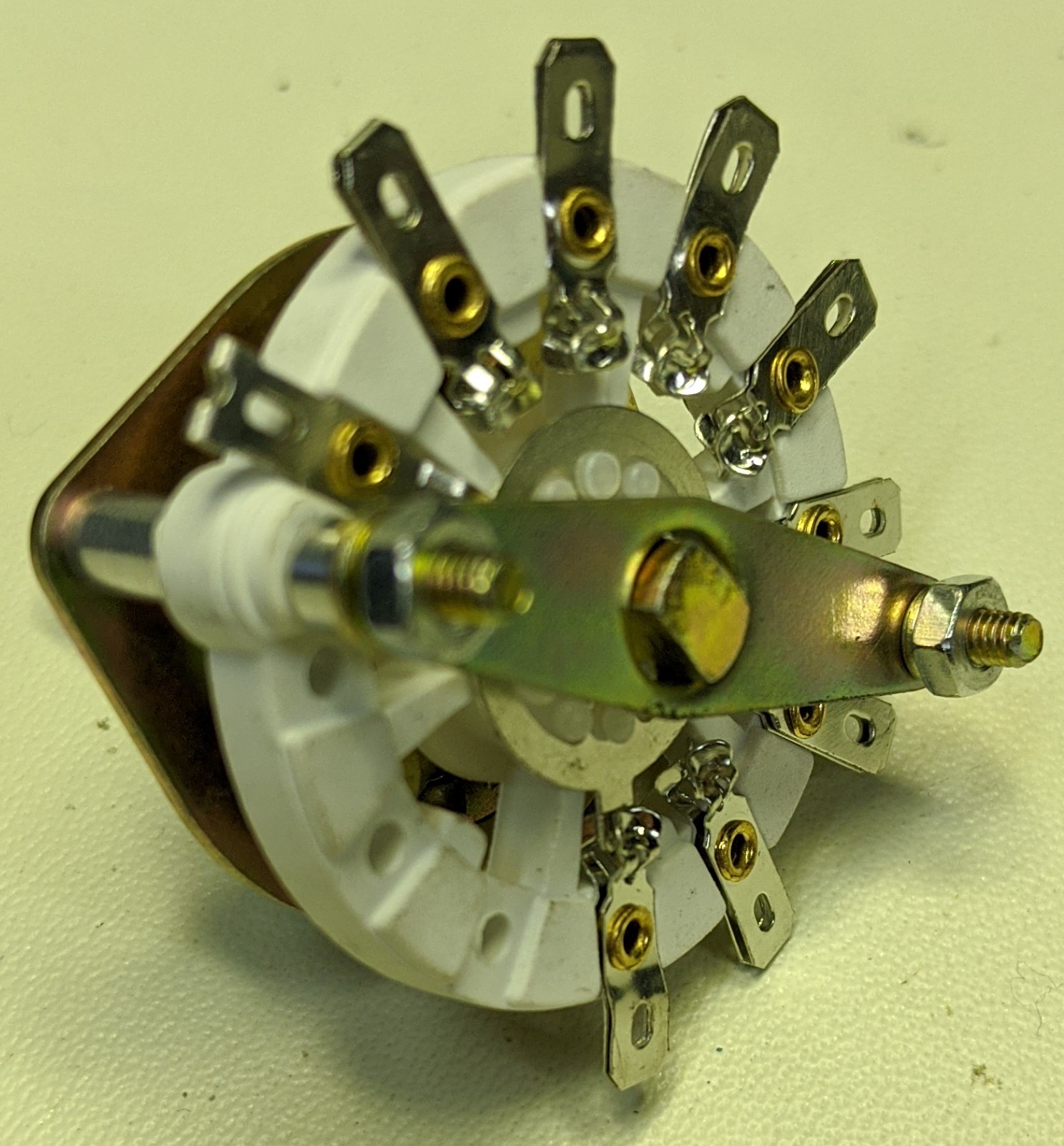
The rotary switch is an 8 position single deck unit.
![]()
![]()
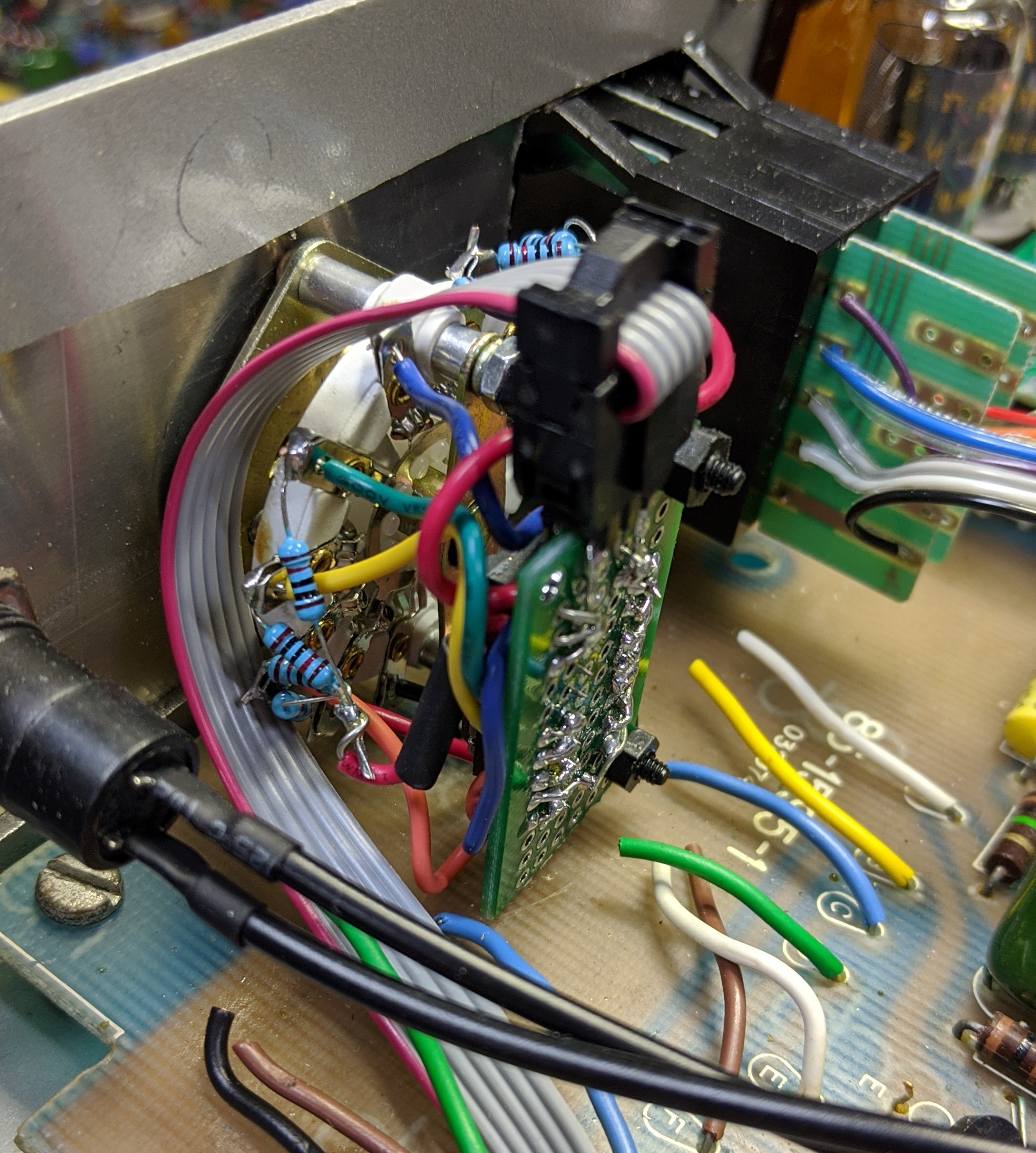
To reduce the conductors required for the internal connector cable and the input pins on AVR controller, I soldered up a small piece of proto-board with a 74HC148 8 Line to 3 Line Priority Encoder IC and 10K pull-up resistors on the inputs. Like the BCD encoded thumbwheel switch, this reduced the AVR input pins from 8 to 3. The little board screwed to the back of the switch and provided the 6 pin dual row IDC header for the cable connection to the controller board. The cable provides +5v, gnd, and the three conductors for the BCD encoded selected value.
![]()
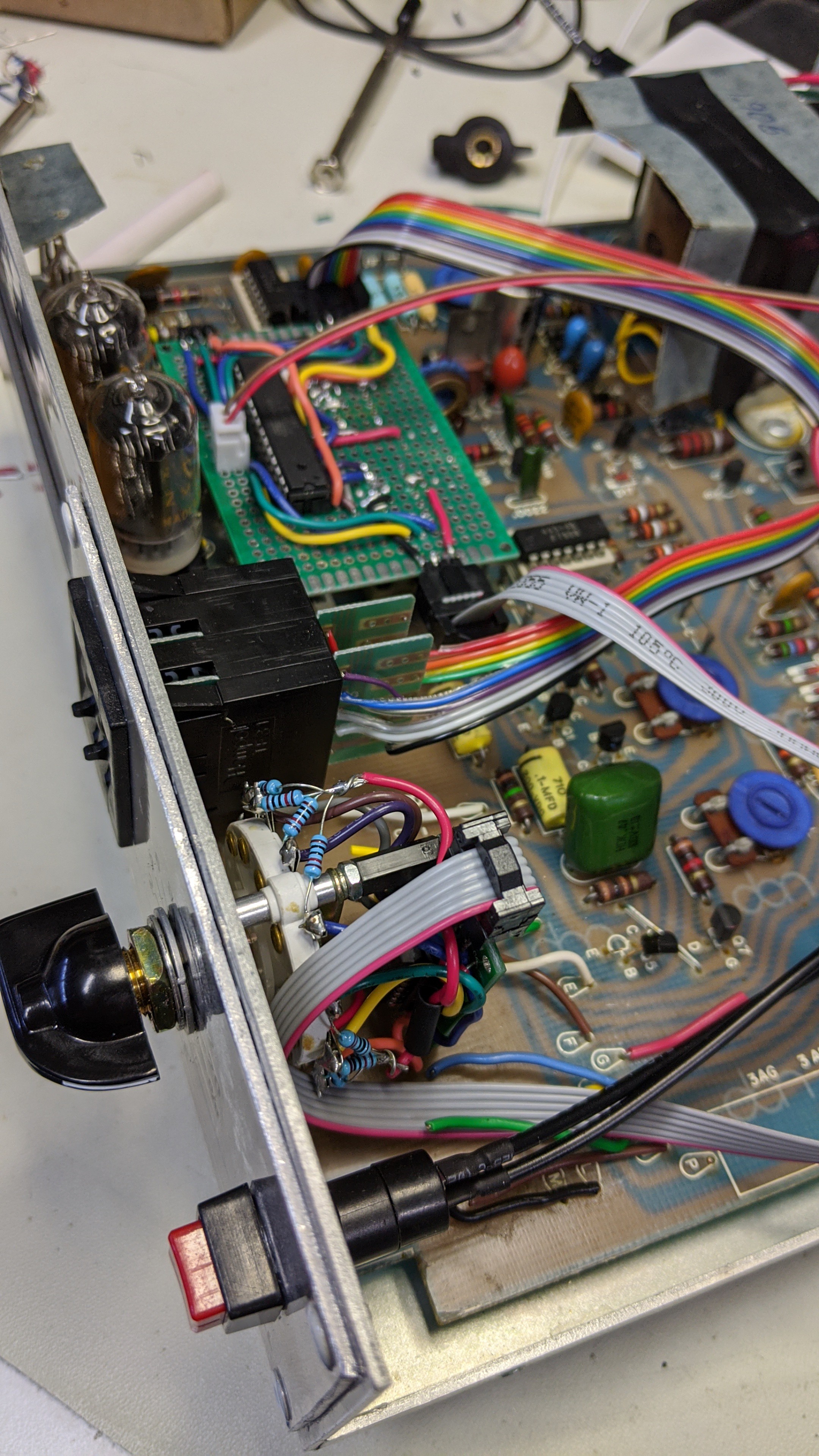
The three cables routed back to the controller board like so.
![]()
-
Let there be light...
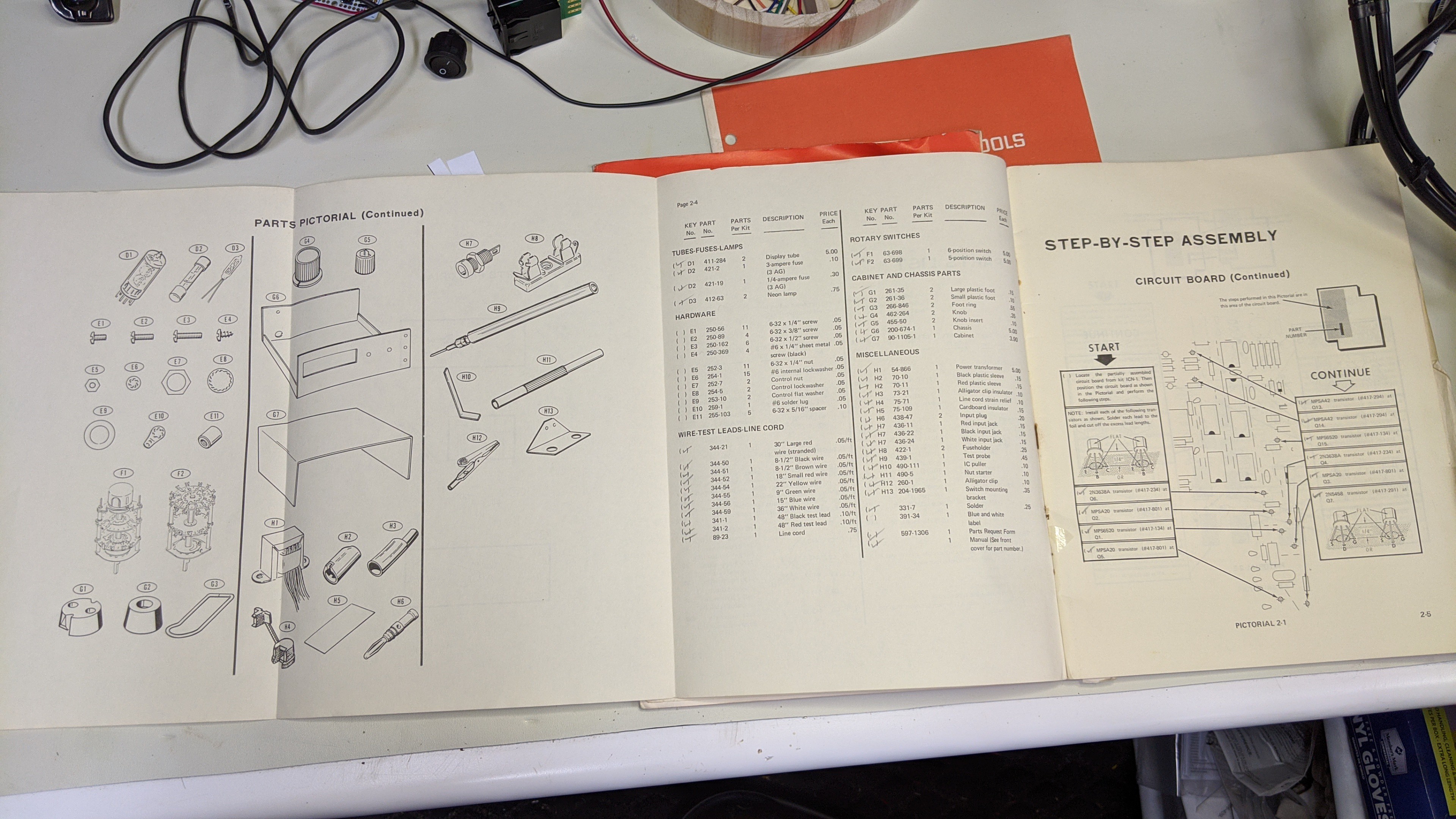
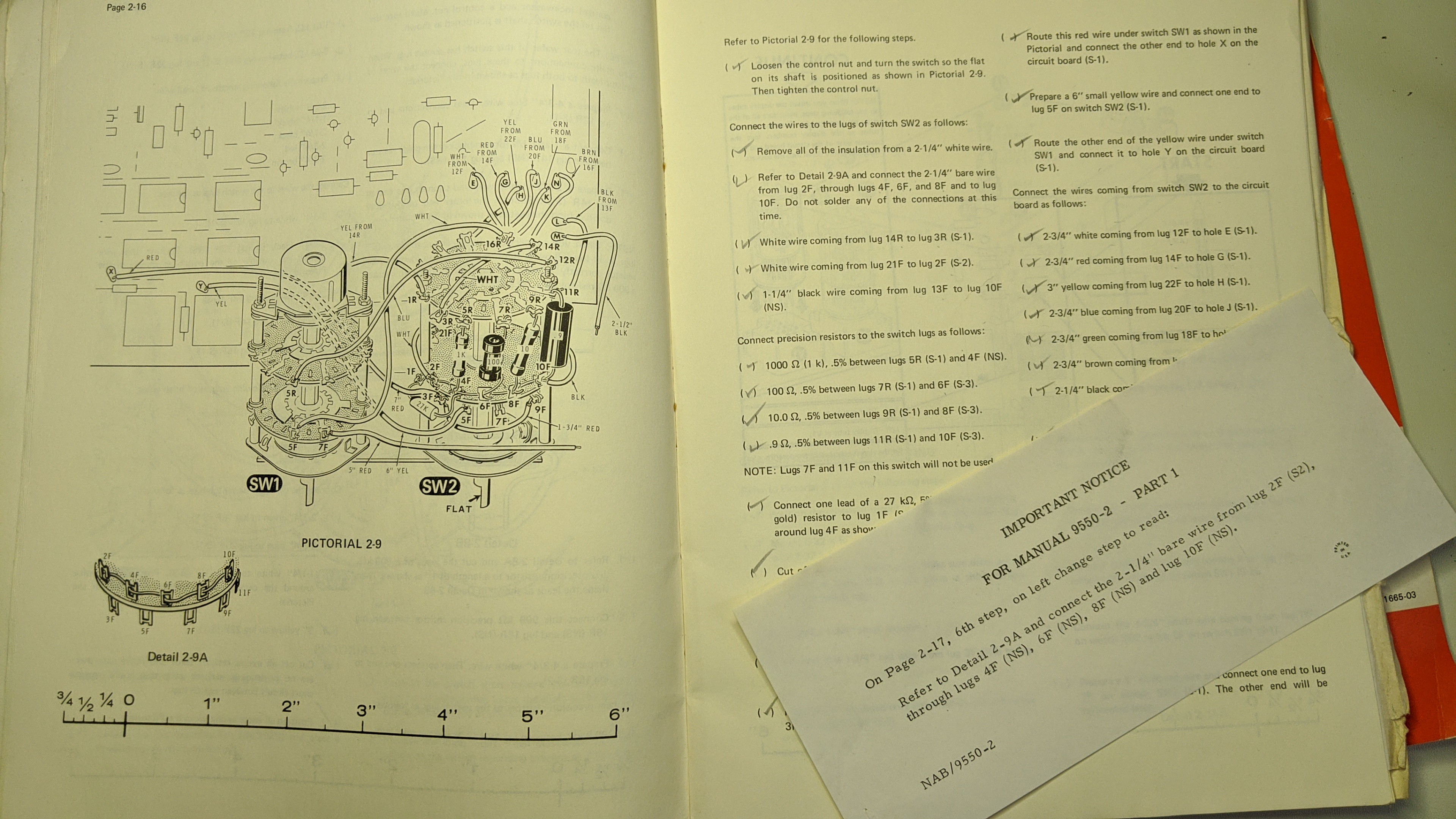
01/17/2020 at 03:28 • 0 commentsSince demonstrating the first version of this project, a couple of my friends have requested that I build one for them. So I've been scanning my usual sources for one or two more of these old meters at the right price. I found and purchased one just last week that happened to include the original assembly manuals. I'm a tinkerer and not much of a collector. So, I'm not looking for complete sets of anything or factory originals. And, as I posted in a previous log, I already have enough information to tinker at will with these meters. But once it arrived with manuals included, I couldn't help but dig through them.
![]()
I'm impressed with the detailed BOM, instructions, drawings, diagrams, waveforms, specifications, and troubleshooting steps provided.
![]()
Some of the drawings are beautiful and there's even errata included.
![]()
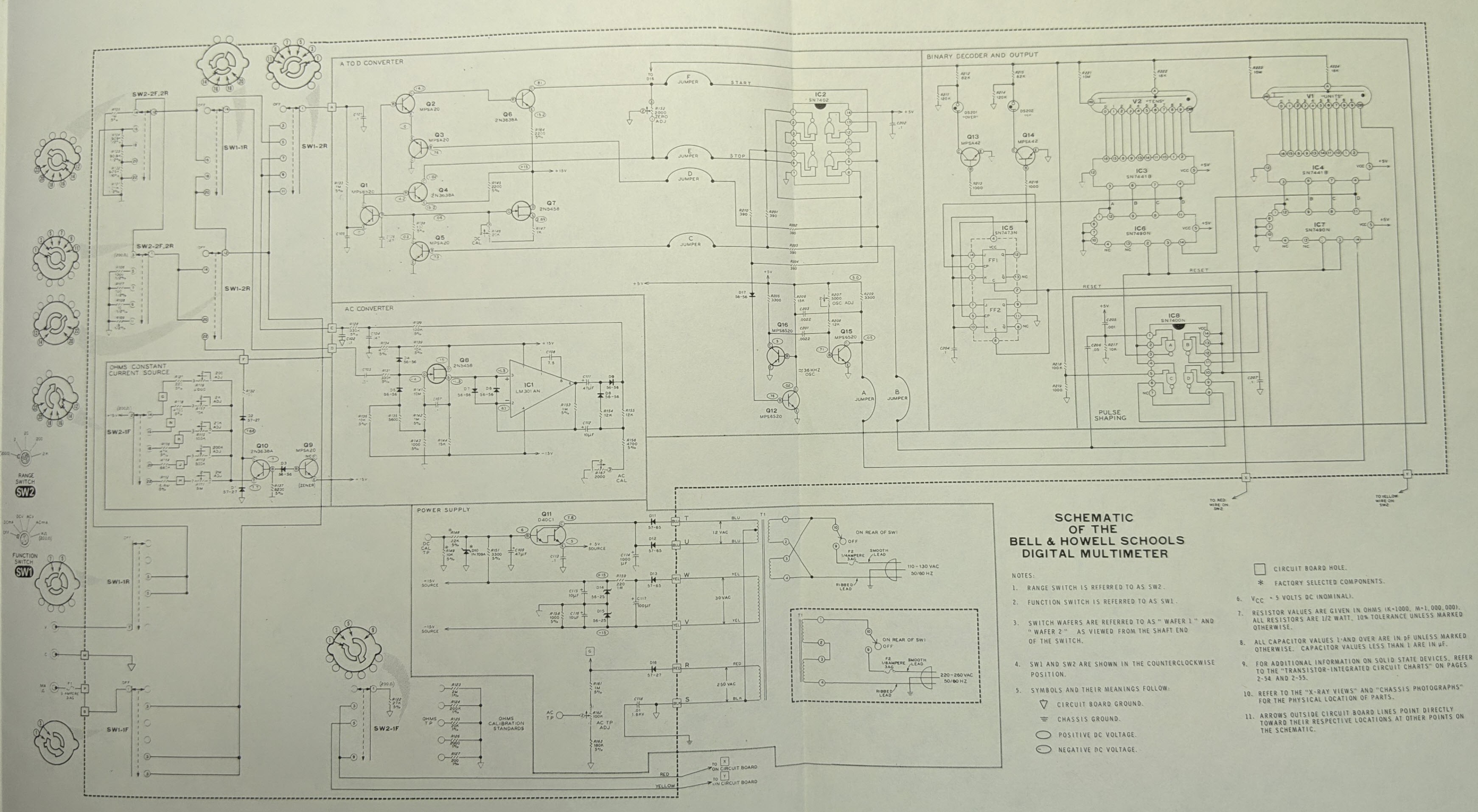
Here's the full system schematic from the manual.
![]()
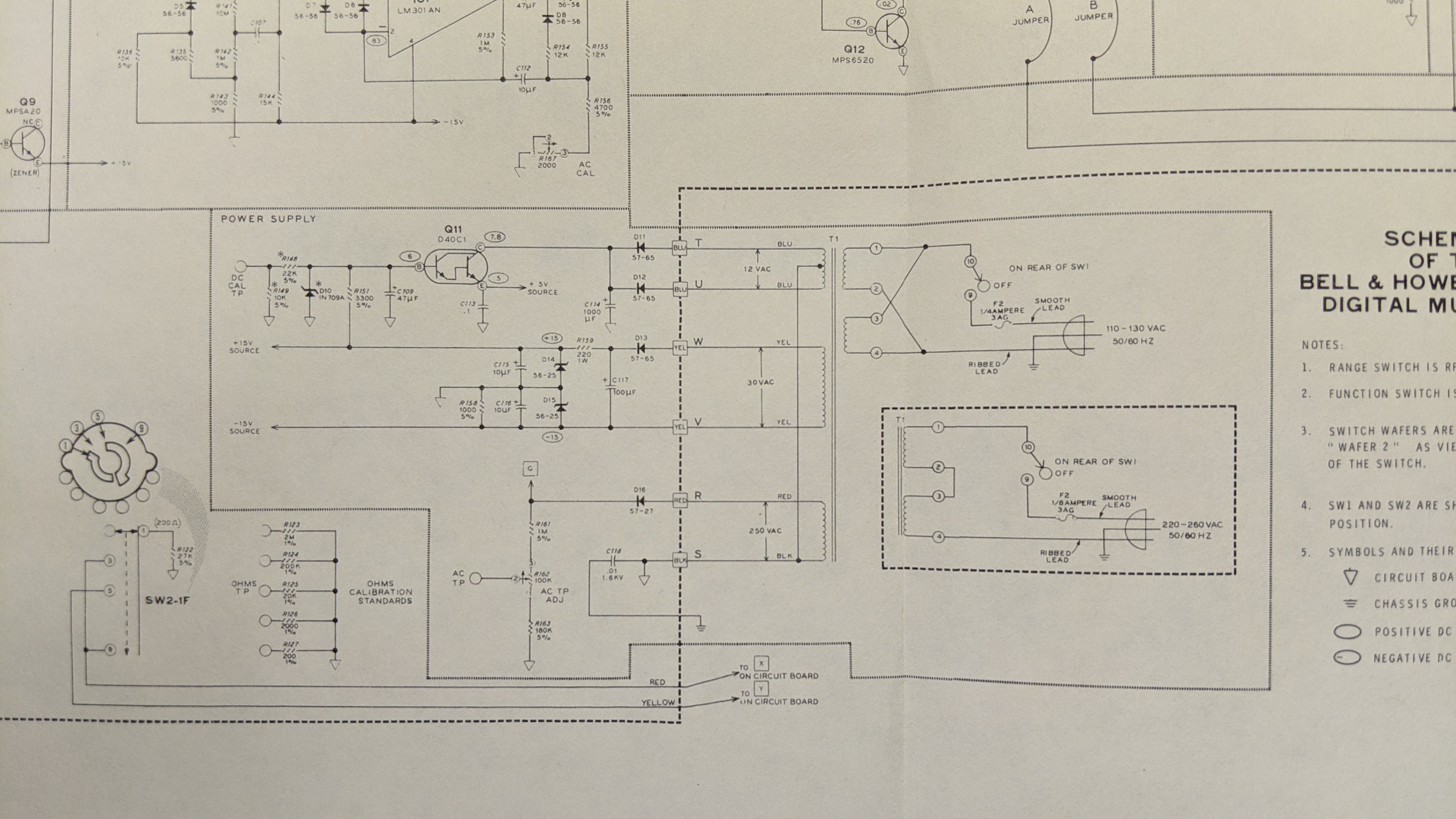
Here's the Power Supply section in more detail.
![]()
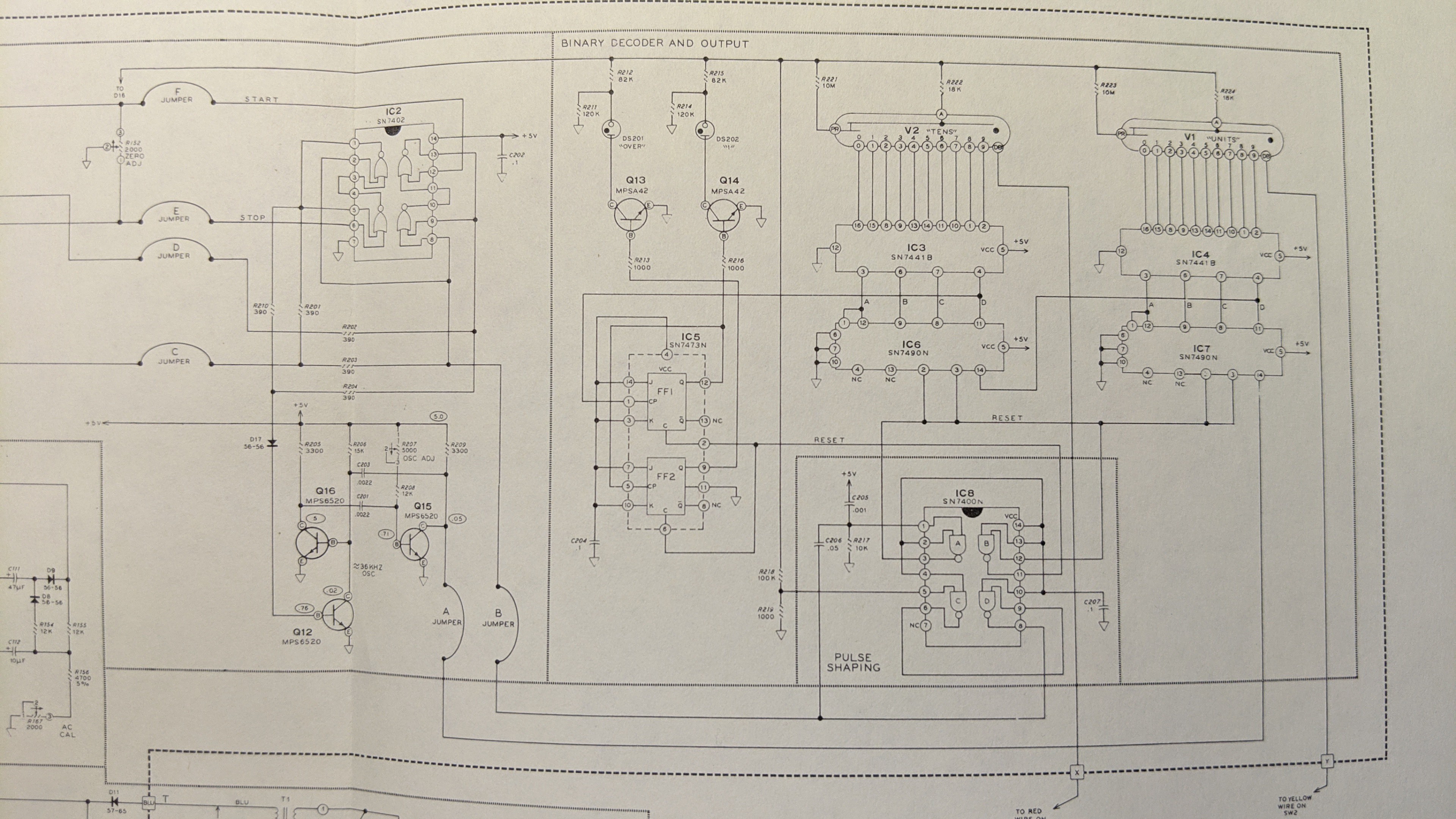
And lastly here's the Binary Decoder and Output section in detail.
![]()
Quickly scanning these, I don't see any changes from the IM-1212 schematics I shared in a previous post. But, I thought I would include these here for completeness sake. If you are playing with one of the meters and have a request for a specific diagram, waveform, or x-ray view, post a comment to the project and I can post something here. Don't get greedy though. I'm not going to scan major sections of the document :-)
1978 "Heathkit" D&D Digital Dice Tower
Resto-Mod Dungeons and Dragons Digital Dice Tower based on a 1975 Bell & Howell IMD-202 Digital Multimeter