Project done. Thesis handed. A literally colossal amount of stress later. In the end I managed to get the motor manufactured by utilizing a couple of third party companies. Though I had to increase my budget in order to do so.
Due to the lockdown I had to make everything at home DIY-style.
I think my favorite, and most successful, DIY endeavor was probably making the stators. Armed with the steel cut outs it was actually quite satisfying to make the laminated stators, using masking tape to both bond the sections together and provide a lamination between the layers. Subsequently setting them on fire was probably superfluous, but did help to spread the adhesive throughout the layers.
Unfortunately the motor didn't turn. I strongly suspect that this was partially because I didn't put enough windings onto the stator (the coil I bought was quite inflexible), but mostly because there wasn't enough power. It seemed that it wasn't possible for me to draw anywhere close to the 4 Amps that I had initially predicted would be possible.
I suspect that this was due to the power supply used. The original plan was try the device with 8 AA batteries but then if that didn't work, as I suspected it might not, I was going to use a purpose built three phase power supply unit at the university. Unfortunately though I did not get this chance.
Regardless though I measured the flux magnetic flux produced by the stator coils. As I suspected I found the flux density to be significantly lower than what would be necessary for motor actuation.
After much journeying through the murky world of commercial laser cutting and 3D Printing I have been forced to abandon my BLDC Spherical motor as it would cost far too much. As it stands I have already managed to spend my budget twice over by cannibalising the budgets of other students who have been forced to abandon their manufacture.
But at least the one of my designs can still get made :).
Progress
Turns out that, thanks to covid-19, and with little else to do but go for runs and watch films on Netflix with my housemates, lots of progress has been made. Weird that.
Power Supply
Done! Finally and after such a very long long time. This aspect of the project I started working in October!
What I now have is a fully functional bit-bashing 3 Phase AC Current generator powered from batteries. Although in practice I am limited to 12V and 4A by my choice of Arduino motor shields, it would not take too much more work to use my motor shields as relays for a much potent supply of power.
Though I have yet to conduct a formal test of its capabilities, by looking at the LEDs on the circuit the system appears to be capable of supplying power at anywhere from between 1Hz to 40Hz. However I may be able to widen this range by changing the prescaler value on the system clocks.
Hopefully I will post a video tutorial on how to do this soon if anyone is interested :)
Manufacture
After spending a significant amount of time over the last week trying to contact and then, in one instance, haggle with various metal cutting, laser cutting and 3D-printers I have managed to arrange for the majority of my components to be manufactured external.
So that's good, all that's left now is to assemble my pieces together. Though that could be easier said than done considering that I really do not have access to many tools in my student house. Perhaps I'll go home to do that stuff.
Numerical Simulation
As I mentioned in my last log I have moved to put the burners back onto this aspect of the design. After some tinkering I finally overcame a small issue which had been stopping any of my previous simulations running, a consequence of my version of the software being more recent than that of the youtuber I was learning from.
Not that it matters anyway as my last simulations were done in January and my design has changed significantly since that point in time.
My current plan is create 3 or maybe 4 simulations:
Three Phase Induction Replica
A replica of the three-phase induction motor I saved from the scrap-heap so I can validate my power supply against what its supposed to do.
Linear Induction Machine
A representative linear-induction machine. In order to prove the concept behind my method of operation.
Circular Linear Induction Machine
Using the same parameters as the linear induction machine to describe a linear induction machine in the shape of semi-circle. Through this exercise I should be able to show that the assumptions about applying linear induction logic to a rotating machine are justified.
BONUS ANALYSIS: My Model
Strictly speaking not necessary as the points I am trying to prove should be proved in the previous simulations. Additionally because my model was designed with ease of manufacturing and assembling in mind the design parameters, such as slot design and stator thicknesses, are not consistent with the other designs.
Additionally I do not believe it is possible to create spherical geometry in Ansys Maxwell (Though I could be wrong).
Could still be quite cool though.
^^So far all simulations are being run in 2D as the simulation time is much, much, much faster and time is pressing. If I am confident in the validity of my 2D sims I may run some in 3D in order to see what impact this has (end-effects etc.),
Testing Rig
Some very unexpected and accidental success here. Upon realising that my super - cheapskates hall effect sensors weren't giving results that made any sense (like at all, they would go haywire as soon as magnets went near them, though they would then remain haywire after that regardless of magnet presence).
To remedy this I purchased, for six quid, a board intended for use on a drone. It contained an IMU, Gyroscope and also a magnetometer. Ostensibly this was only supposed to be for reading the Earth's magnetic field and should have been too sensitive to accurately record the magnetic flux that my neodymium magnets were producing.
Fortunately they worked just fine and had the added bonus of being able to give the exact global co-ordinates of the IMU at the time of the magnetic reading!
I then realised, as may seem obvious to the reader, that this would allow me to essentially paint a map of the flux densities around my stator in both time as well as space. Fantastic!
Also the board has a temperature sensor. Not useful for my project though it was quite useful for checking for fevers. #2020 problems.
Since my last log the university has shut-down almost entirely (extending and then moving forward the Easter holidays) and the chances of actually manufacturing my design look increasingly slim ... Not least because I'm already at my budget limit .... lol.
There are still ways in which I can manufacture my project (and the DXFs and STLs are ready to go) but if it does happen then it will be considerably later than I had anticipated.
The Path Forward
Need to have a little google hangout with my supervisor on Monday, but the avenues I could put more time into are as follows:
1. Get as much to the ready-to-manufacture stage as possible.
To compensate for the lack of manufacture this could be expanded to include a camera rig for detecting the speed of the motor or developing additional performance tests and the C code to allow them.
2. Make an educational video detailing the project, how it works and how to go about making it.
- This is quite appealing to me as I've got a fair amount of experience with Blender, SolidWorks Visualize and Adobe Creative Cloud. Also love making videos :)
3. Double down on the Numerical Analysis with Ansys Maxwell.
Something I've not talked about too much recently as it really went on the back burner in order to get this thing made but there was always a plan to do a full numerical analysis of the system using ANSYS Maxwell. I ended up running into a few issues with it so I focused on the analytical model but I should probably start to re-focus on that.
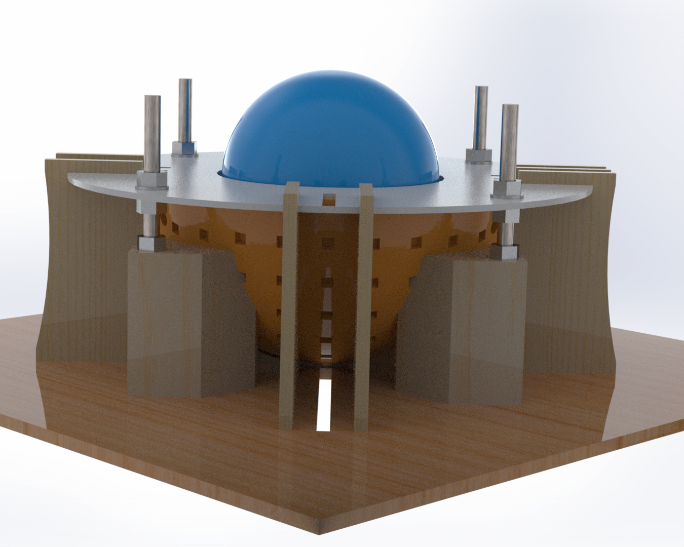
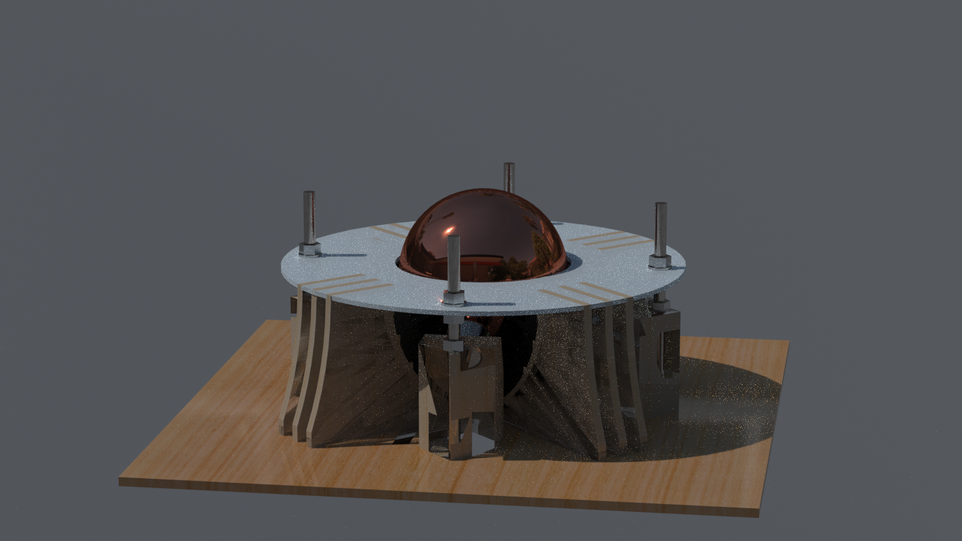
- These are just a couple of preliminary mock-up renders to give the basic idea of what each set-up will look like. The glaring issue here is that the winding and consequent wiring set-ups are not included. That is certainly the next and most immediate step, not least because the design will probably have to change a little (particularly for the BLDC version) to accommodate this.
Owing to the outbreak of Covid-19 the University has, unsurprisingly, shut down the student Maker space, which was where I had intended to produce the majority of my components... Starting today.
Though I have the option of moving to a more design and analysis based project I'd really prefer not to because I really want to make that ball spin (dammit!).
I have contacted the Makerspaces in and around Sheffield and there seem to be two (AccessSpace and Sheffield Makerspace) that seem like busy hubs of innovation. Perfect!
I have also contacted a laser cutting company such that I can produce some of my parts. Unfortunately they do seem to want to charge about £100 for the work, which is quite a lot all things considering that my budget is supposed to be £200 (And i think i've already gone over (lol) ). Could be worse I suppose.
We'll see what the Maker spaces have access to in terms of facilities etc. and go from there.
Design has been finalised, with changes only to be made for tweaks in manufacture.
The plan is to produce 3 separate devices that can all be assembled on the same rig. i.e. they are all modular devices.
Device #1: AC Induction Sphere:
Stators: 4 Perpendicular Stators
Rotor/Sphere: Hollow steel sphere with copper shell
Coil Excitation: 3 Phase AC
Rotation Mechanism: Stator magnetic field interaction with eddy currents in rotor shell.
Device #2: BLDC Sphere
Stators: 4 Perpendicular Stators
Rotor/Sphere: ABS Sphere with 187 Neodymium magnet [N52] studs
Coil Excitation: Pulsed DC
Rotation Mechanism: Stator magnetic field interaction with Neodymium magnet studs.
Device #3: Flux Measurement Device
Stators: 1 Stator
Measurement Device: 10 Hall Effect Sensors on a breadboard
Coil Excitation: 3 Phase AC
Measurement Mechanism: Position Hall Effect Sensors around rig and measure the flux the magnetic flux strength.
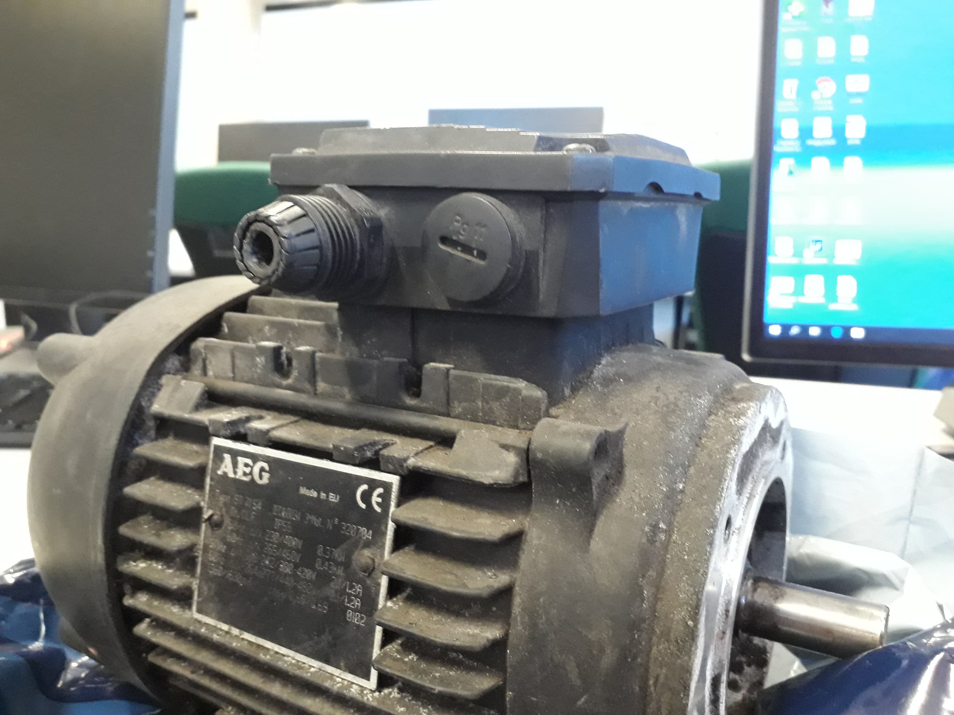
-BONUS DEVICE: Old AC Induction Motor -
Went looking around for coils and stators at a motor repair shop in Sheffield and came across this beauty.
Took the seized bearing out and will connect up my power supply soon. This should determine if my power supply is suitable in its current form.
Power Supply
Basically *fingers crossed* fixed! By using the Arduino Mega and 3 Motor boards being controlled separately I was (after sometime) able to produce 3 phase AC current. The big issue was powering all 3 motor shield processors from one Mega, the problem was compounded when one of my solutions caused a motor board to start smoking. I figured the cause of this may have been that I was still missing a pin in my wiring set up (Shields are supposed to be connected to all pins on an Arduino Uno). To remedy this I placed the shield on an Uno but connected the relevant pins to the Mega. This appeared to work as intended :D.
The Steel Solution
I have accepted that with my budget the only way to progress is to just use regular mild steel sheet for my stators (and steel sphere sections). Hopefully this could still give me relative permeability values of around 1000 (which is pretty good), but I am prepared that I may get much lower values. The lack of knowledge as to what values I would get has lead me to propose the flux measurement device so that I can lump all parameters into a single parameter. i.e. how strong is the magnetic field that actually gets produced.
Dilemmas
- Steel is expensive!
I have been forced to reduce the wall thickness of my sphere so that i can fit my sections within other sections. Turns out Halos do not make the most efficient use of space and I really don't have an awful lot of budget left.
- Forced Dimensions Changes -
After finding a pre-built copper shell (from a 4.5" float valve), which was always going to be the hardest thing to manufacture myself, I needed to scale up all of my designs to accommodate a 115mm rotor rather than a 100mm rotor. This is very doable though it means that my previous work in the IForge goes to waste :/
- Coil Windings -
I have definitely not given this as much thought as I should have. My current plan is to use a dLRK winding scheme ( as is currently used by hobbyist aircraft enthusiasts, and the connect the wires together using a star/delta arrangement. I'm going to talk to the uni electronics guy tomorrow so hopefully he'll say what I should do.
- Sensors -
With the various arduino power supply concerns I have not really spent enough time setting up my sensing rig.
The sensors to be used will consist of
- On-board Current Sensing from the Motor Shields. As these are already connected to the Arduino UNOs, I should be able to access the current data very easily indeed. The Arduino "Serial.print" function does not have the ability to print to file. However I can include the relevant clock cycle of any reading, making provisions for the delay between the printing of the clock cycle and the printing of the data, and copy/paste the data from Serial.monitor.... Though currently CNTL C/V isn't working too well. - May be able to use a third party software such as Putty or Hyperterm.
- Hall effect Sensors to sense the Magnetic Field Strength, same method as before in terms of copy/pasting off of the Serial monitor with the relevant clock cycle/ time stamp. Need to work on calibrating those sensor readings. - I might be able to do this by using the neodymium magnets which supposedly have a rated magnetic field strength (~1T).
- Speed Measurement - This is going to be harder. For the BLDC sphere I may be able to use a hall effect sensor to detect the passing magnetic studs. For the Induction sphere I'm going to struggle. One possible solution would be to paint two circle loops in different colours around the azimuth and elevation axes and just count their passing over a period of time. If I had two sets of power supplies I would be able to prove that the angular velocity would be a superposition of the angular speeds around each axis. Sadly that would be too expensive :/
Next log should pretty much just be manufacture and me being my told by the university that my electronics are not safe enough in their current form. :P
It's been a while, but quite a bit of progress has been made.
Research
Nothing really on the research front, the focus has been more on getting models built and stuff made :)
Rigs
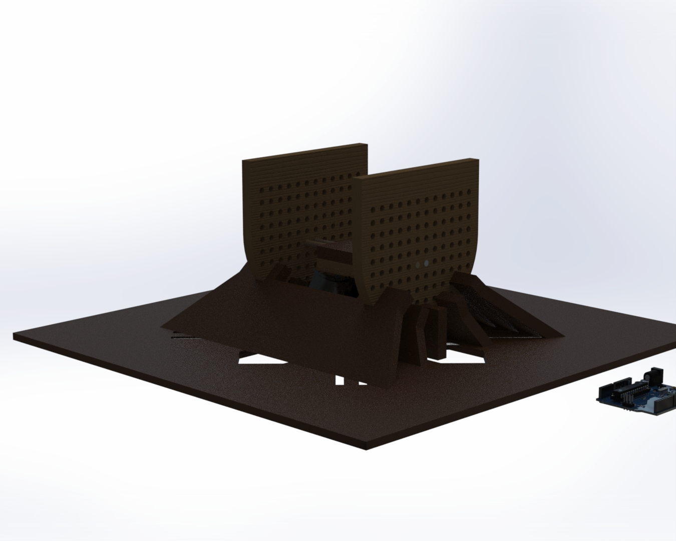
An additional rig has been designed. This will allow for the measurement of magnetic field strength (flux density) from my device. Hopefully this means that in the event that my device doesn't turn I can at least show I am on the right track.
Also I have started to produce parts of my Rig using the IForge makerspace at Sheffield Uni. Pretty great place not going to lie.
^Lots of holes
^Oooo what lovely blond hair that experimental rig has!
Analytical Calculations
In the last log I claimed that this would only take a number of days to complete.......
Almost two months later I now have a pretty robust analytical model for predicting the performance of the spherical drive system. Here's a graph!
-The attentive amongst you may realise that the Torque value is not especially high. In fact it is concerning low, hence my back up plan of a magnetic field measurement device to prove that my plan (sort of) had potential.
Electromagnetic Simulation
Did give this another crack but my model is throwing up a lot of errors that seems tricky to fix with only the guy on YouTube to look at for help. I think I might endeavour to find someone at the university who knows how to use this software.
Power Supply
My solution to this problem, which I had encountered just before the last log entry, is to use an Arduino Mega instead of an Arduino Uno to generate the power.
This should be possible on account of the additional timers that the Mega has when compared to the Uno. 4 available timers versus 1 timer. (There are more timers on both boards but they are required by other functions).
The Mega will then act to control 3 Arduino motor shields, offsetting the phases by 120 degrees each. Each board being powered by 3 independent 12V Voltage sources (i.e. 8 AA batteries in series).
Upcoming Dilemmas
Dilemma #1
- The time is fast approaching to start building the stator. This will require me to go to some effort and expense purchasing steel sheet and using the water jet cutter to cut it out. The problem is that the relative permeability of the steel is the key parameter, the values of which vary wildly depending on the grade of steel in question and it is a property which is rarely considered by most suppliers of regular (i.e. cheap) steels. Therefore I have no real guarantee as to what the relative permeability of whatever steel I purchase is. This is something I need to fix, perhaps there is a supplier of stator-grade steels at the university?
Dilemma #2
- I really have no idea if my Mega powered 3-phase solution will actually work, or if my code is any good.
Dilemma #3
- Time! this thing has to finished by like April! :O! Crikey!
As this is my first log in the Hackaday context I thought I'd share where I'm up to at the start of this new decade (and approx. halfway through my project).
Research
and boy has there been a lot of this.
Dare I say that by the current stage of the project this section is complete?
Probably not, but if I have to come back up from the little research hole where I've burrowed into then it means something has gone horribly, horribly wrong.
Rigs
So far a rig has been developed in CAD. This rig will house a singular stator, a cylindrical rotor and the whole collection of Arduino, batteries and electronic circuits that go along with it. The foundations of the rig can also be used to support the spherical rig once that has been designed.
Analytical Calculations
Rough pen and paper calculations so far, but looking to generate some more concrete figures in MATLAB over the coming days.
Electromagnetic Simulation
By using the Ansys Maxwell software provided free by my university (and after watching some number of youtube videos by a bloke called Kamyar K.) I will be able to more accurately simulate the performance of my drive system, hopefully informing my design such that the final iteration will at least turn. Even just a little bit :P
Progress here has been hampered partially by Ansys' immensely unfriendly user interface, but mostly because most of my time in the recent month or so has been spent trying to solve the problem in the next section...
Power Supply
The real crux of the problem. Once this has been solved then this whole project will become a good deal more straightforward.
Essentially, I know that I need to generate at least two (preferably 3) phases of AC current from a DC power supply. In the previous term I attempted to do this almost solely within the context of Arduino, as I was quite inexperienced with conventional electronics and eager to learn more about programming in the process.
To this end I combined an Arduino UNO with a few Arduino Motor-shield Rev 3.'s and developed some code to output a PWM signal that mimicked a sinusoidal AC waveform, using the motor shield's L298 H-Bridge to invert the signal every half period. This gave me control over the frequency of the signal as well as giving me the option to easily use sensor feedback to adjust the performance of the device.
Before Christmas I thought I had managed to achieve this, as indicated by the attached image. However upon trying to combine the two half signals into one or apply a low-pass filter circuit the waveforms generated did not look at all correct. (These circuits were very basic however, only featuring a sparse collection of resistors and capacitors).
So to all those who have struggled to the end of this post -
Anybody got any advice when it comes to generating 3 Phase AC power from an Arduino-based system for an electronics newbie? Any tips would be appreciated :D
-Also if the advice could focus on the Arduino + Motor shield Combination then that would be ideal, as I have already put a reasonably large amount of my project budget into those components. (Not the end of the world though).
By using our website and services, you expressly agree to the placement of our performance, functionality, and advertising cookies.
Learn More
 Alex Dunnett