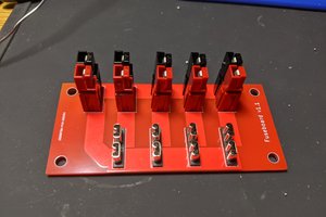
The project is divided into three main steps. The socket / driver board, the power / logic board, and the enclosure.
I built the socket / driver board first then busted open an older Nixie tube clock project to get a 170 volt power supply and Particle Photon to test the socket / driver board:
Once the socket / driver board was completed, I moved on to designing and building the power / logic board. I used an off-the-shelf Nixie power supply to generate the 170 volts needed by the tube anode. I used a Particle Photon to control the clock. The socket / driver board is really just a 5 volt power supply, some level translators, and some wiring to connect everything together. The heavy lifting is performed by the power supply and Particle Photon boards.
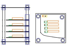
Once I verified the socket / driver board and the power / logic board worked together, I designed an enclosure in Fusion 360. Here's a screenshot of a cutaway view of the enclosure showing how the two boards, enclosure, and mechanical parts fit together.
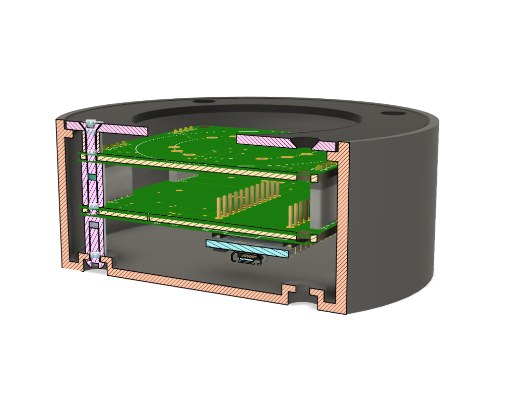
The enclosure is 3D printed using HP's MultiJet Fusion (MJF) 3D printing process. After printing, the enclosure is dyed black. The lid of the enclosure is cut from a piece of anodized black aluminum. The final step was to finish the software for the Particle Photon. Because the enclosure is plastic and does not block RF, I could assemble everything then use the over-the-air update feature of the Particle Photon to finish the software.
Complete details are on my blog:
https://bikerglen.com/blog/dalibor-farny-rz568m-nixie-tube-socket/
https://bikerglen.com/blog/dalibor-farny-rz568m-nixie-tube-controller/
https://bikerglen.com/blog/dalibor-farny-rz568m-nixie-tube-enclosure/

 Adam Demuri
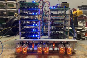
 Sean B
 cyplesma
When you want a Dalibor Farny clock but can't afford six tubes...
Honestly, I like the one-digit-at-a-time thing - it's got a simplicity to it. Nice job.