A dial indicator is used to accurately measure linear displacement. A typical indicator can measure up to 1 inch of movement with a resolution of 1/1000 of an inch (for those of us using antiquated imperial measuring units.) Usually, the large needle rotates once around the dial face to indicate 0.100 inches of travel and a smaller needle counts (2x) 5 or 10 rotations.
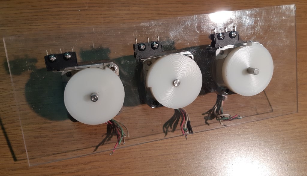
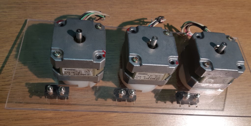
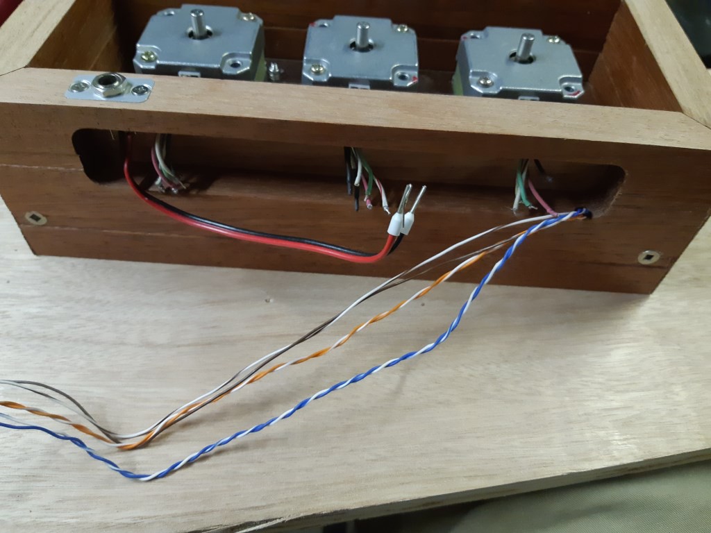
Thus was born the idea to carefully displace the measuring tips of a trio of dial indicators, allowing hours, minutes and seconds to be indicated. Hobby servos could provide the required displacements but would probably suffer from poor resolution and position control. So I chose some stepper motors from the junk bin. One hundred thou displacement is controlled with a spiral cam pressed onto each stepper motor shaft.
In order to give the MCU some position feedback, I added a microswitch to each cam. The switch releases at the end of the 0.100" travel and closes again somewhere (sometime?) before full travel is reached again. The actuating lever on the microswitch serves a subtle second purpose too. A typical indicator measuring tip is rounded or partially spherical shaped. This would not snap cleanly back to the start of travel as the cam (slowly) rotated past the tip. By placing the indicator tip on the actuating lever, the lever acts as a sharp edged follower which drops immediately as the cam rotates past the highest spot. Software could compensate and rotate the cam quickly through the transition spot but instead a simple mechanical arrangement solves two issues in one go.


 Quinn
Quinn
 charliex
 dekutree64
What a cool project. Do you have a link to the Displacement Cam that I can download and print?