Close
0%
0%

Dial Indicator Clock

Dial indicators are common measuring instruments in the machine shop and are often referred to as clocks. Can they tell time too?

Similar projects worth following
Using dial indicators to tell time when not busy indicating eccentricity.

A dial indicator is used to accurately measure linear displacement. A typical indicator can measure up to 1 inch of movement with a resolution of 1/1000 of an inch (for those of us using antiquated imperial measuring units.) Usually, the large needle rotates once around the dial face to indicate 0.100 inches of travel and a smaller needle counts (2x) 5 or 10 rotations.

Thus was born the idea to carefully displace the measuring tips of a trio of dial indicators, allowing hours, minutes and seconds to be indicated. Hobby servos could provide the required displacements but would probably suffer from poor resolution and position control. So I chose some stepper motors from the junk bin. One hundred thou displacement is controlled with a spiral cam pressed onto each stepper motor shaft.

In order to give the MCU some position feedback, I added a microswitch to each cam. The switch releases at the end of the 0.100" travel and closes again somewhere (sometime?) before full travel is reached again. The actuating lever on the microswitch serves a subtle second purpose too. A typical indicator measuring tip is rounded or partially spherical shaped. This would not snap cleanly back to the start of travel as the cam (slowly) rotated past the tip. By placing the indicator tip on the actuating lever, the lever acts as a sharp edged follower which drops immediately as the cam rotates past the highest spot. Software could compensate and rotate the cam quickly through the transition spot but instead a simple mechanical arrangement solves two issues in one go.
  • 3 × Dial Indicator
  • 3 × Stepper Motor
  • 3 × Displacement Cam A spiral cam with a single 0.100 inch tooth
  • 1 × Frame Whatever you have that looks nice. Ideally thick enough to carve a cavity in the bottom to fit the electronics.
  • 1 × Support Window Clear Plexiglass, 1/8" thick, roughly 4 x 9 inches. Supports the stepper motors and the microswitches.

View all 10 components

  • Construction Details

    vegipete02/04/2020 at 19:28 0 comments

    Here are some more photos of construction details of the Indicator Clock.

    The material I had lying around included solid oak plank flooring, about 0.7 inch thick and 1/8 inch thick Plexiglas sheet. So that's what I used.

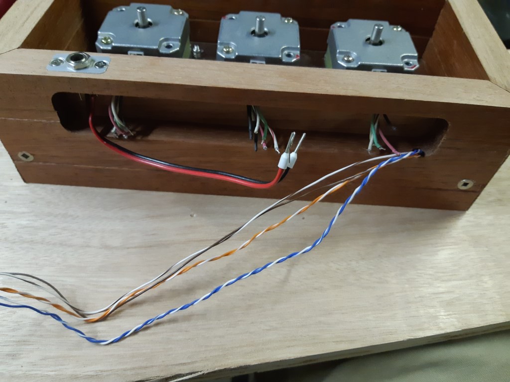
    Threading wires through the frame

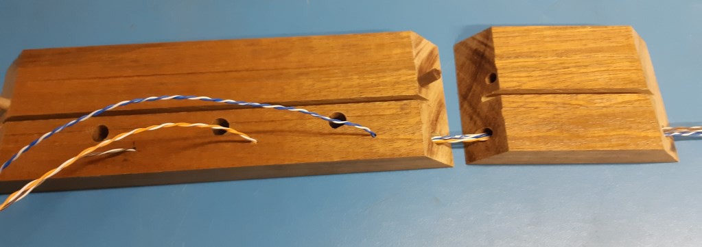
    In order to neatly route the limit switch wires, I chose to thread them through holes drilled in the frame. Cat 5 twisted pairs were stiff enough to push through. A dowel pin increases joint sturdiness. The kerf from the saw 'nicely' matches the Plexiglas thickness.

    ========================================================

    Gluing the frame together

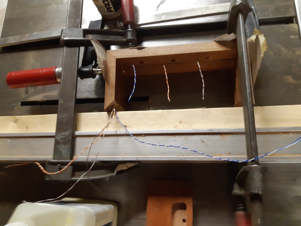
    With the wires in, I glued the top and sides together. Servicing those wires in the future will be ... not an option. No room for mistakes or trimming too much wire.

    ========================================================

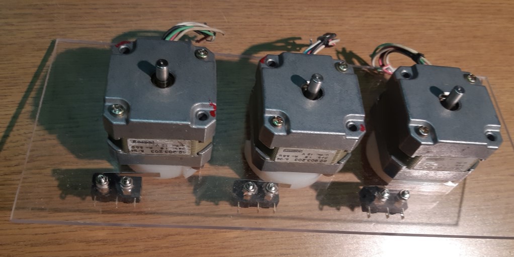
    Front view of the motor assembly

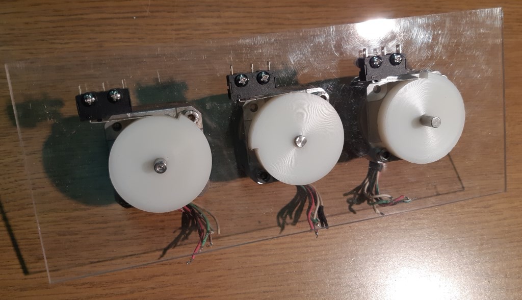
    Rear view of the motor assembly

    A piece of Plexiglas sheet serves as a nice mount for the three stepper motors, as well as the cam sensing limit switches. Stand-offs hold the limit switches out from the sheet a bit so they line up with the cams, which are just pressed onto the motor shafts. Time will tell if the cams will stay in place. Curiously, my collection of 1/8" thick Plexiglas sheet was not exactly all the same thickness so I tested a few different pieces to find the best fit in the kerf. Most of it was slightly thinner.

    ========================================================

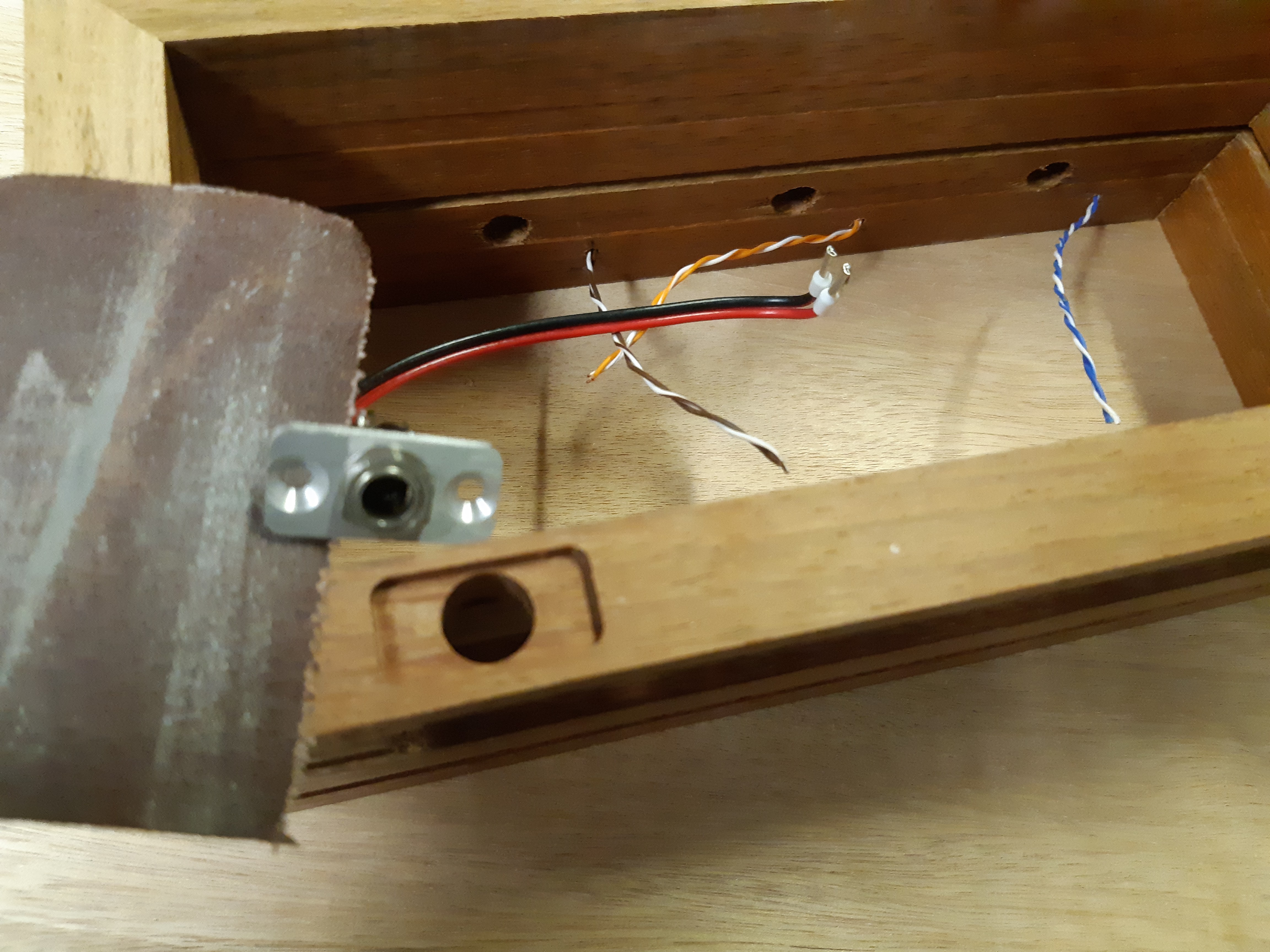
    Fitting the power jack

    The wood frame is too thick to directly screw the power jack I had in place. The solution? A small aluminum plate. A matching pocket in the wood, two little screws and some time carefully sanding and in goes the power jack.

    ========================================================

    The control pocket

    A pocket milled into the base allows the electronics to be neatly tucked away. If it ain't neat and tidy, [SWMBO] will not tolerate this clock in the living room. Then again, she doesn't tolerate the rest of the machine tools in the living room so the point is perhaps moot. The base is held on with two screws (Robertson, can you tell I'm Canadian?) so there is a chance of some disassembly, providing I leave enough surplus limit switch wire to pull it apart.

View project log

Enjoy this project?

Share

Discussions

shepler007 wrote 01/05/2021 at 00:10 point

What a cool project.  Do you have a link to the Displacement Cam that I can download and print?

  Are you sure? yes | no

Dr. Cockroach wrote 02/06/2020 at 22:02 point

In years past I have had to scrap indicators such as those..... Damn, wish I held some back from those days. Cool project and use of those dials :-D

  Are you sure? yes | no

ekaggrat singh kalsi wrote 02/05/2020 at 23:33 point

this is brilliant!..  i need to add this to my unending project list 

  Are you sure? yes | no

Dan Maloney wrote 01/24/2020 at 17:28 point

I love this! Best part is that you dealt with the transition at the end of the cam mechanically, instead of in software.

The question is: would it be worth doing this with just one stepper? You could just drive the seconds dial indicator and then gear that down 60:1 for minutes and 12:1 (or 24:1) for hours. Making the gear train would be a challenge, I suppose. Still, a cool idea - not that it would make your build any better, of course. Just different ;-)

  Are you sure? yes | no

vegipete wrote 01/24/2020 at 17:35 point

I also envisioned displaying the date at the touch of a button, requiring (as far as I can tell) independent control of each indicator. But I like the idea of a gear train.

  Are you sure? yes | no

Gerben wrote 01/24/2020 at 14:43 point

I thought the lever was to reduce wear on the tip of the indicator.

Do you still use those indicators, or they "spares"?

  Are you sure? yes | no

vegipete wrote 01/24/2020 at 16:51 point

The hardened tip of the indicator sliding quite slowly (except maybe the second hand) on the nylon cam wouldn't wear very quickly. But you are right, the lever will protect it more. Mind you, even a completely knackered tip will still indicate just fine, unless the measurement set up requires accurate symmetry.

When finished, I want the clock to be a storage rack for the indicators. Take one out, use it, drop it back in when done and note the change in time for billing the customer.

  Are you sure? yes | no

Ken Yap wrote 01/23/2020 at 23:12 point

Hahaha, 👍 ! The machinations 😉 people will do to tell time.

  Are you sure? yes | no

Similar Projects

Does this project spark your interest?

Become a member to follow this project and never miss any updates