John Lonergan
-
More data on limits
05/25/2021 at 18:12 • 0 commentsDuring the design I chose current limiting resistors that were low enough to properly drive the chip being tester, but not so low as to damage the chip if the IO is being driven by opposing levels, eg driving 5v from the tester into a pin that is currently an output with a low value. In this situation the current limiting resistor prevents damage to get test device and the circuit under test.
However I came across this recently in the Phillips HCT User Guide, in section 8.2 "Push-pull outputs", it says ...
"A shorted output will also cause the maximum DC current rating to be exceeded. However, one output may be shorted for up to 5 s without causing any direct damage to the IC."
There is more info on that page.
Assuming most folk will be working with CMOS then I expect this to be true of most/all? devices and so my current limiting resistors could have been smaller still or perhaps non-existent as long as the tester only enabled it's pins momentarily to test the device and then went back to hi Z.
This is intuitive I think as any damage would be caused by heating and so a very short pulse would cause very little heat.
Thus is just an observation for a possible simplification of this setup.
The high value resistors on the other test pin of each pair is still needed to facilitate the tristate tests. If you don't care about those tests then the tester world work without any resistors and using only half the GPIO pins. But I really liked the idea that this device would be able to make strong assertions about all output types. I believe this tester would also correctly test/identify open collector variants.
https://assets.nexperia.com/documents/user-manual/HCT_USER_GUIDE.pdf
-
Video - Exploratory GUI demo
03/03/2020 at 03:51 • 0 comments -
Interactive Exploratory GUI
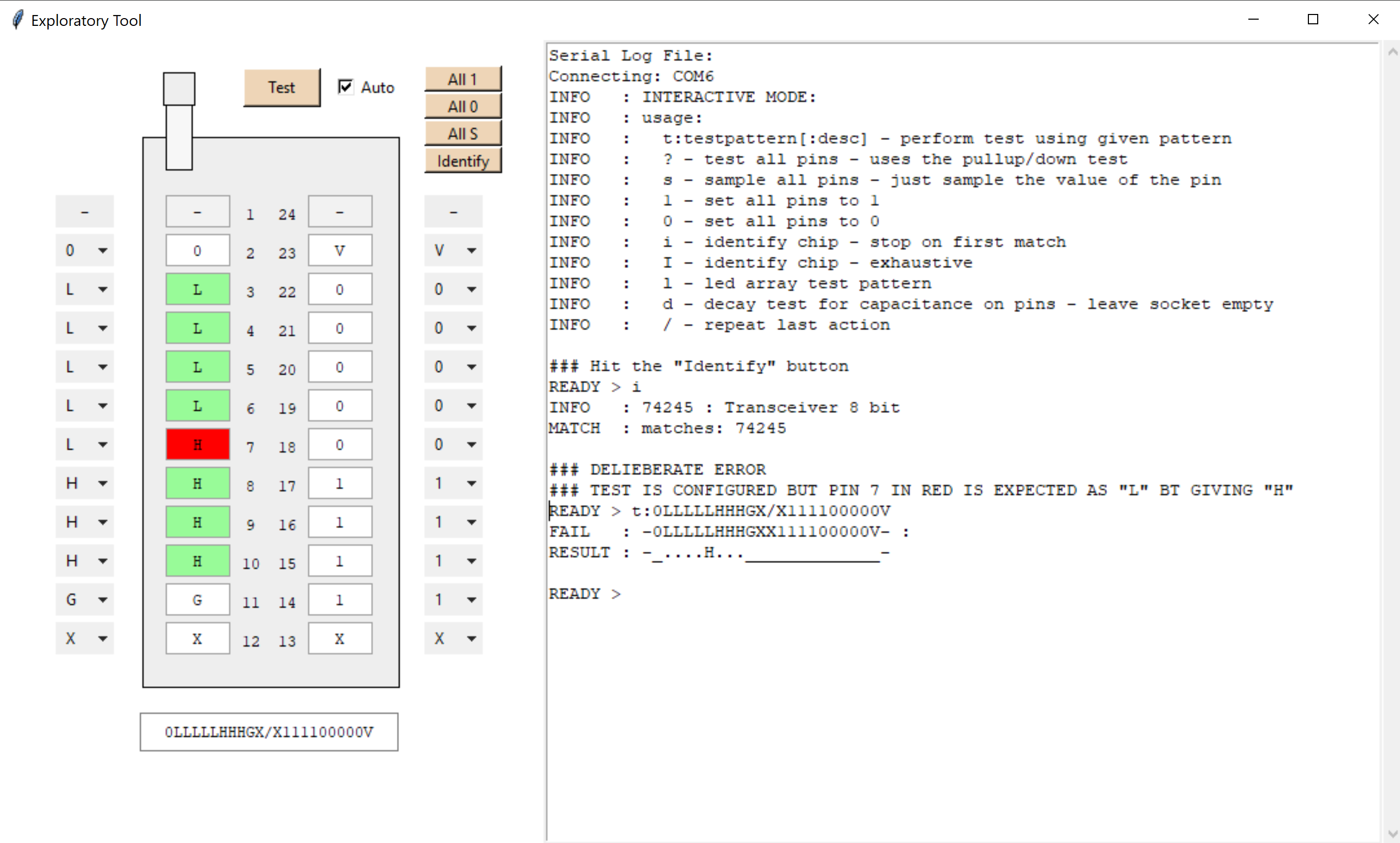
02/26/2020 at 02:58 • 0 commentsGot around to creating a GUI for the exploratory function.
Alows one to pick the config for the test pins and then displays the result of the test, highlighing the outcome of any pin value expectations in green and red.
![]()
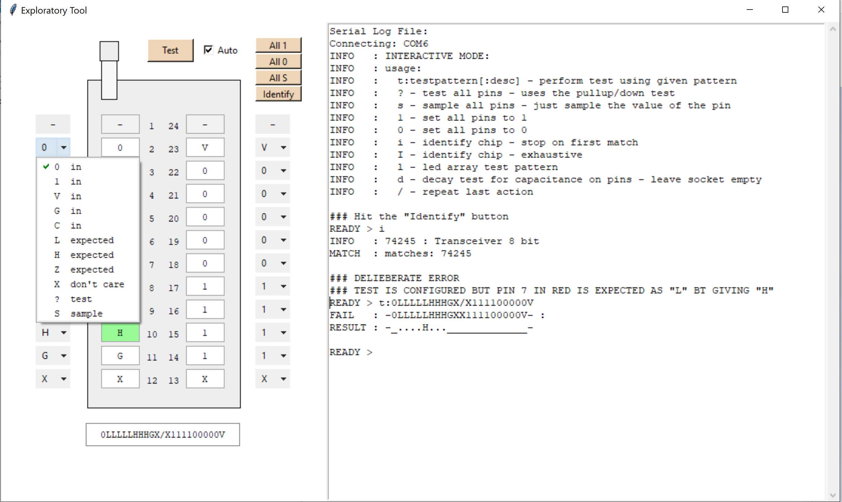
Each pin is equiped with a cfg drop down...
![]()
-
Interactive mode, Graphical UI or done for now??
02/19/2020 at 02:13 • 1 commentAt this stage the project has almost served it's purpose.
There's one more thing I might invest in and that's a graphical UI for the interacgtive mode across the serial interface.
It would make the exploratory side of things a lot easier.
Toggle pin states, apply, see results etc.
Python or Java I suppose - any suggestions?
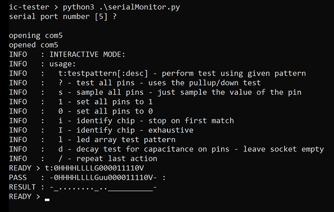
The interactive mode is now complete along with various options. I've included a serial monitor that uses the readline library to make usage a lot more convenient.
![]()
-
Video - Interactive Mode and Usage
02/19/2020 at 02:10 • 0 commentsTake a look
-
High-Z test possible using only 1 GPIO pin?
02/10/2020 at 23:10 • 0 commentsI use currently dedicate two GPIO pins per test pin in this device and this allows me to distinguish between 1/0 and Z outputs.
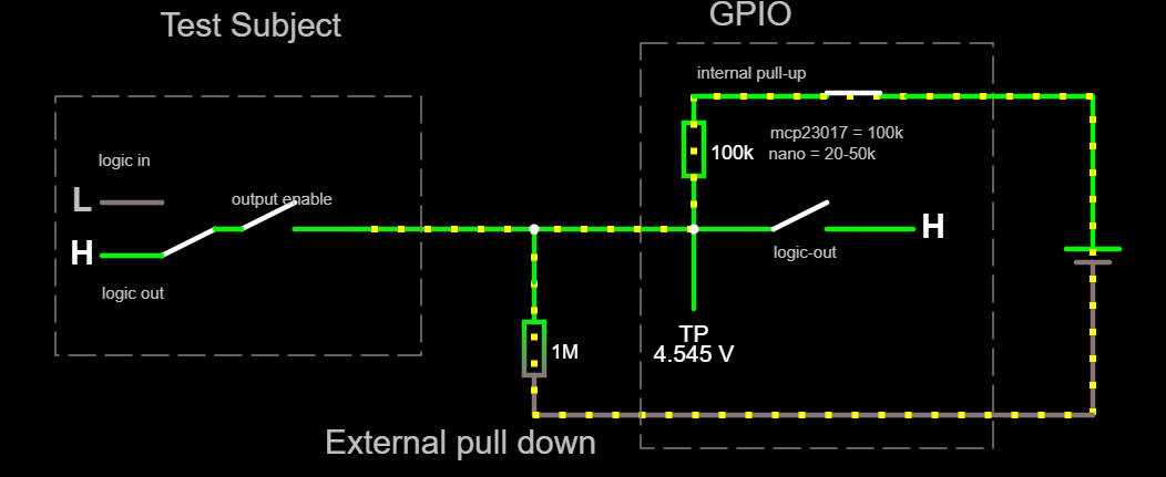
I was wondering if I'd missed a trick, and whether I could have done this reliably with only one pin plus a pull down resistor.
See simulation .. http://tinyurl.com/usm9eqd
Firtsly, I don't think this idea works at all if I want to support TTL because I need an external pull down resistor who's value is able to pull-down a high-Z line but without interfering with reading a high logic level. That means we need a high value.
However if we use a very high resistance for the pull-down then the input low leakage current (out) of the devices will ensure that we are not able to achieve a 0.8v low anymore.
However if we use a low value then this will pull down the line so much that we can't achieve a valid logic high.
This page explains pullup/down value selection and the problems associated with poor choices https://www.electronics-tutorials.ws/logic/pull-up-resistor.html (recomended).
Turns out the max pull-down for TTL is 2k !! This is assuming an input leakage current of 400uA and a max valid low threshold of 0.8v Eg 74LS245 is 200uA
By contrast the MCP23017 has Input a leakage current of 1uA , 74HCT is 0.1uA, ATmega328p is 1uA which might allow for a pull down of something like 800k perhaps.
However, even 800k would probably pull the logic high down to 4.4v and since this device is already pushing it a bit with voltage levels I'm not keen on taking a device that I've found reliable in testing and then making it flakey.
So - no after all.
-
Video - Principle of Operation
02/10/2020 at 03:56 • 0 commentsThis video discusses the principle of operation of the device and provides a few CircuitJS sims of the modes of operation of the test pins.
-
Interactive Demo of Principles of Operation
02/08/2020 at 20:24 • 0 commentsThis tool demonstrates how the two GPIO pins are able to distinguish a tristate high-Z state (or empty socket) from a bistate high/low output.
The demo is linked off the github page.
But see the Principles of Operation on github for how it works.
(Built using Falsted/Circuitjs)
![]()
-
PCB for free!
02/08/2020 at 00:40 • 0 commentsI have a box of the v1 PCBs for this project.
If someone wants one and postage from London isn't excessive then drop me a message.
These boards work fine as long as you seat the chip in the second row of the zif as there was a problem on row one due to me misunderstanding pins A6 and A7 of the Arduino
Cheers John
-
Interactive
02/07/2020 at 17:14 • 0 commentsInteractive mode now working so this will be the basis of coms for a companion program that will run on a PC
Integrated Circuit Tester & Exploratory Tool
Interactive tester and exploratory tool for logic chips