-
1Physical Build
The build is pretty straightforward:
- Attach the e-Paper display to the HAT using the supplied ribbon cables
- Attach the e-Paper HAT to the GPIO headers
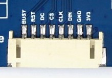
- Attach the e-Paper ribbon cable to the e-Paper display
- Follow the SlimPi install instructions over at Git Hub (don't forget to enable SPI and setup the configuration files)
- Run SlimPi and rejoice
It's a good idea to mount the e-Papper display on a stiff backing board as it is quite fragile. From there, find a picture frame with adequate space inside and mount the display inside.
NOTES:
I ran into a ton of problem using the included ribbon cable and found that the female GPIO header on the HAT had some faulty connections leading to all kinds of streaking and ghosting issues.
If your display has streaks, poor black quality, or is generally not functioning properly, see the Trouble Shooting instructions for help.
-
2Trouble Shooting
Lousy Image Quality
You may find that your display may not display blacks correctly, or regions that should be black appear white or streaked with white. See the images below.
Text should be entirely black
Background should be entirely black
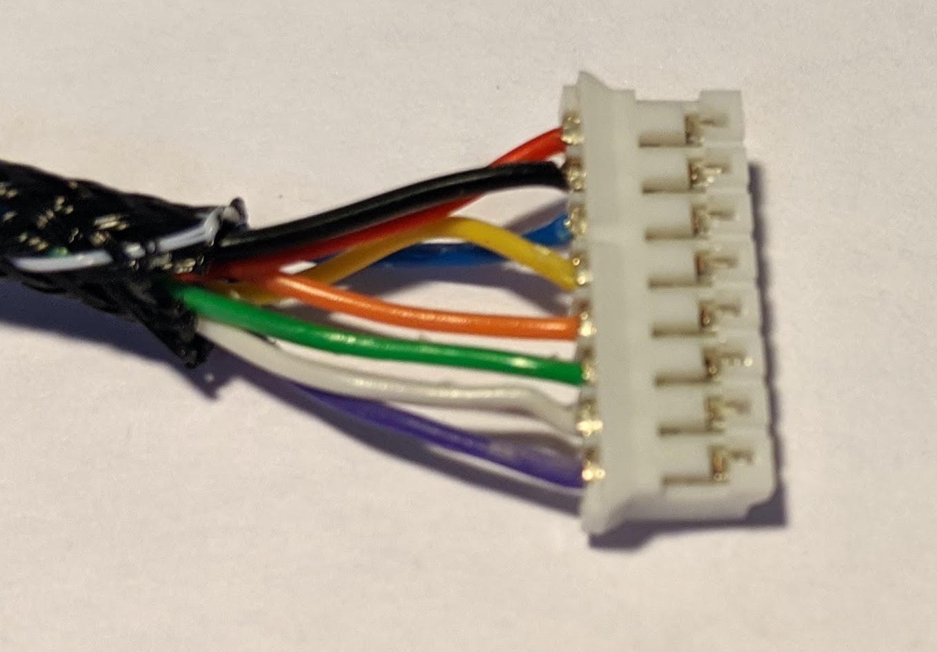
After hours of trouble shooting, swapping out panels and HATs, I eventually determined that some of pins in the female GPIO header were not fully making contact with the Pi GPIO Male headers. Switching to the JST connector (white connector with 8 wires) included with the board resolved these issues. The JST connector appears to be a better choice all around.
I ended up building my own JST connector to give myself a bit more length. Check the parts list for all the connectors required and the Cable Build instructions for help in making the cable.
Permission Errors
If you receive "PermissionErrors" when starting up SlimPi, check the log output. It's likely the Pi user does not have access to the SPI and GPIO block devices or the SPI devices are not setup.
Check the System Setup instructions over at git hub.
-
3Cable Build
Tools
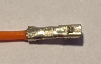
If you choose to build your own cable for connecting the pi to the display, I suggest purchasing a quality pair of crimpers. There's no hope of properly crimping the ends using pliers. Crimpers are absolutely required.
That being said, there's a lot of variety in the quality of the crimpers. The ratcheting type featured on AdaFruit are GARBAGE. This style of crimper works by crimping all portions of the crimp in one go.
The die crimps both the wire crimp and the wings that fold over the wire insulation. This seems great, but unfortunately it is nearly impossible to see what you are doing. If the crimp-end is not placed exactly in the right spot on the die, it will be horribly ruined.
Instead, I suggest the Engineer PA-09 or the PA-21. These crimpers are much simpler and more elegant. It takes twice as many motions to crimp each wire, but you can see exactly what you're doing and it is much less likely that you will ruin your crimp end.
Crimping
If you've never crimped JST or Dupont style ends, I suggest buying a lot of extra as you will likely waste a few. Check out this short video for quality instructions.
Materials
See the Bill of Materials attached above
Construction
- Measure 8x 22-26AWG wires preferably of different colors
- Cut a piece of braided wire sleeve approximately 15-20mm shorter than the desired length of wires.
- Add heat-shrink tube to the sleeve
- Cut two pieces of heat-shrink tubing about 10-15mm long
- Thread the heat-shrink on now so you don't forget it later!
- Thread the measured lengths of wire through the braided wire sleeve.
- Thread a stiff wire such as a solid-core wire or coat hanger through the sleeve first.
- Fasten the 8-wire bundle to the wire using masking tape
- Pull the bundle through the sleeve
- Add 8x JST crimp ends to one end of the cable
- Check this video for excellent instructions
- Add 8x Dupont crimp ends to the other end of the cable
- Use the same method as above for the Dupont connectors
- Install the JST crimp ends into the JST connector
- the flat side of the crimp end faces toward the open side of the JST connector (shown below)
![]()
![]()
- the flat side of the crimp end faces toward the open side of the JST connector (shown below)
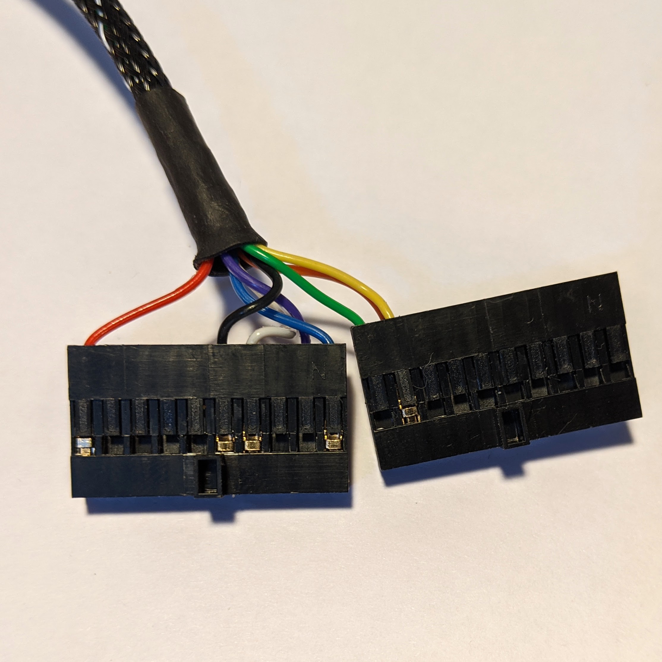
- Insert the Dupont crimp ends into the 40 pin Dupont Connector - see the pinout in the documentation
- Use care and match the appropriate wires to the appropriate position in the connector
- NOTE: the BOM specifies 2x10 pin connectors - use two, side-by side to make a 2x20 connector
![]()
![]()
- Shrink the tubing on at the ends where the sleeve meets the wire.
- If the sleeve is too long, this is a good time to trim it.
![]()
- Gently snap the JST connector into place (it is indexed and can only fit in one direction)
- DOUBLE Check your connections. Swapping 3.3V and Ground is a GREAT way to let the magic blue smoke out of your display driver.
- I mean it. DOUBLE CHECK your connections.
- Push the Dupont connectors onto the (powered down Pi) - pin 40 is is closest to the USB ports.
- Power on and start testing!
-
4Disable Pi Lights
The power lights are quite bright and a bit ugly. As I write this, the headline on HackADay is all about the how we ruined status lights. How very apropos to these instructions.
It is possible to disable the lights automatically at boot time using a bit of scripting and some systemd services.
Use the provided install script to disable the LEDs at boot time. For more information, check out the instructions over at GitHub for more information.
$ sudo ./install/install_led_ctl.sh
The HiFi Berry also has a very bright green light on the top. This can be minimized with a bit of tape, or by gluing a straw over the top of the LED. I used a little rubber cement and a piece of heat-shrink tube cut to about 8mm.
Adding a straw over the top limits the viewing angle for the light. This maintains its usefulness as a power indicator, but renders it much less distracting.
 Aaron Ciuffo


Discussions
Become a Hackaday.io Member
Create an account to leave a comment. Already have an account? Log In.