-
1Setup
Dr. Wattson comes with a companion acrylic enclosure, so that the AC wires are enclosed and you can use it in a safe manner. The enclosure is available on Tindie as well - https://www.tindie.com/products/upbeatlabs/enclosure-for-dr-wattson-energy-monitoring-board/
![]()
![]()
I have prepared a User Manual showing how the wiring is to be done, which is now available on GitHub.
The digital out that is coming from Dr. Wattson is completely isolated from the mains, as the energy measurement is done in an isolated manner using current and voltage transformers, so the digital out is perfectly safe to handle.
Once in the enclosure, all you need to do is plug the cable into an existing outlet, and plug any device into the outlet on the enclosure . It is calibrated to measure currents up to 4A (so I could be able measure really small currents for measuring standby power — the MCP39F521 chip on which it is based has a 4000:1 dynamic ratio, meaning it can measure from 4A down to 1mA). I have also done a 15A conversion - replacing the burden resistors to suitable values and recalibrating the board to be able to measure currents up to 15A.
Arduino Energy Logger with Dr. Wattson — with CFL lamp load plugged in
-
2Circuit
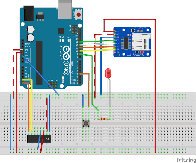
Here is the circuit I used:
I used an SD card breakout similar to the Adafruit one (so I used that in Fritzing, as that was the closest part). The connection is pretty standard — CLK (Arduino Uno pin 13), MISO (Arduino Uno pin 12), MOSI (Arduino Uno pin 11) and CS (Chip select). CS is configurable, though it defaults to pin 10 for hardware CS — I just use that.
For the button, I used the Button library by Jack Christensen, which provides debouncing and a variety of useful stuff in an easy to use package. (https://github.com/JChristensen/Button). The button is using the Arduino’s internal pull-up, so it doesn’t have any external pull-ups and also uses inverted logic (high is OFF, low is ON) — all of these are configurable as parameters to the Button constructor! I’ve hooked up the button to pin 4, but you can use any available pin you like.
I really did not have the time and patience to model Dr. Wattson as a new part in Fritzing, so I cheated, and used the advice of Z-HUT to easily whip up a custom part without much ado. I highly recommend watching it! https://www.youtube.com/watch?v=dfxx8wF3Uhs — thanks Z-HUT! :-)
The only downside is that I have to be content to use the breadboard image of the “generic IC” part that I modified to represent Dr. Wattson. C’est la vie!
Here is a look at Dr. Wattson’s pins (from left to right):
- SCL — for I2C communication, goes to Arduino Uno A5
- SDA — for I2C communication, goes to Arduino Uno A4
- ZCD — Zero Cross Detection — we are not using this feature in this example
- Event — Event indicator — we are not using this feature in this example
- GND — Connect to Arduino GND
- VIN — Connect to Arduino 5V (or to 3.3v on the RPi) - used for bi-drectional level shifting
- 3.3v — Connect to Arduino 3.3v (used to power the Dr. Wattson board)
- GND — Connect to Arduino GND (you only need to connect one of the GND pins)
Here is my Fritzing diagram showing the circuitry:
![Arduino Energy Logger Circuit with Dr. Wattson]()
Arduino Energy Logger Circuit with Dr. Wattson
-
3Sketch
Ok, now to move on to the actual programming! I have added this sketch as an example to my Dr. Wattson library which is available on GitHub - https://github.com/upbeatlabs/drwattson - simply download and install the Arduino library, and run the WriteEnergyDataToSDCard example there!
My data logging is done in files with a name like DATAXX.CSV, where XX is a number (from 00 to 99, so a 100 files). I check the SD card for existing file names, and pick the latest unused file name — for example DATA15.CSV
 char filename[] = "DATA00.CSV";
...
// create a new file
for (uint8_t i = 0; i < 100; i++) {
    filename[4] = i/10 + '0';
    filename[5] = i%10 + '0';
    if (! SD.exists(filename)) {
        Serial.print(F("Data file is "));
        Serial.println(filename);
        // only open a new file if it doesn't exist
        break;  // leave the loop! filename will now be the one we desire        }
}
In the loop() function, once the button is pressed, it toggles the readData variable, which controls if I read the energy data.
bool readData = false;
...
void loop() {
    myBtn.read();                    //Read the button
    if (myBtn.wasReleased()) {
      //If the button was released, change the LED state
       readData = !readData;
       digitalWrite(LED, readData);
    }
    if (readData) {       ...

    }
    ...
}
The data read is written out to SD card in a comma-separated format, to make it easy to import in Excel or another spreadsheet program.
      if (dataFile) {
        dataFile.print(currentMillis);
        dataFile.print(",");
        dataFile.print(fData.currentRMS);
        dataFile.print(",");
        dataFile.print(fData.activePower);
        dataFile.print(",");
        dataFile.print(fData.reactivePower);
        dataFile.print(",");
        dataFile.println(fData.apparentPower);
        // print to the serial port too:
        dataFile.close();
}
Building an Arduino Energy Monitor & Data Logger
How I built an Arduino energy monitor and data logger to collect energy data for different loads and plotted that data using Excel.
 Sridhar Rajagopal
/i/89288/products/2018-02-09T02%3A19%3A15.985Z-DSC_1386.jpg)
/i/89288/products/2018-02-09T02%3A19%3A15.985Z-DSC_1382%20%281%29.jpg)


Discussions
Become a Hackaday.io Member
Create an account to leave a comment. Already have an account? Log In.