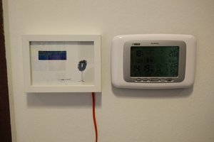
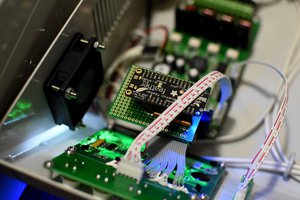
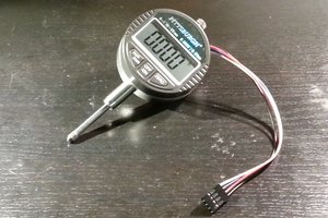
Operates a bit like a DVM but monitors serial data. Self powered. Rechargeable. Very low component count.
These are first few lines of PIC source code
;An internal reset circuit automatically initializes the HD44780U when the
; power is turned on. The following instructions are executed during the
; initialization. The busy flag (BF) is kept in the busy state
;until the initialization ends (BF = 1). The busy state lasts for 10 ms
;after VCC rises to 4.5 V.
;1. Display clear
;2. Function set:
;DL = 1; 8-bit interface data
;N = 0; 1-line display
;F = 0; 5 ´ 8 dot character font
;3. Display on/off control:
;D = 0; Display off
;C = 0; Cursor off
;B = 0; Blinking off
;4. Entry mode set:
;I/D = 1; Increment by 1
;S = 0; No shift
;; // according to datasheet, we need at least 40ms after power rises above 2.7V
; P0 = RS
; P1 = R/W
; P2 = E
; P5:P7 = D0:D3 DATA
;
;RS signal is LOW then the LCD interprets the 8-bit info as Command and
;writes it Command register and performs the action as per the command.
;If the RS signal is HIGH then the LCD interprets the 8-bit info as data
;and copies it to data register. After that the LCD decodes the data for
;generating the 5x7 pattern and finally displays on the LCD.
;
;(RW): This signal is used to write the data/cmd to LCD and reads the busy
;flag of LCD. For write operation the RW should be LOW and for read operation
; the R/W should be HIGH.
;
;(EN): This pin is used to send the enable trigger to LCD. After sending
;the data/cmd, Selecting the data/cmd register, Selecting the Write operation.
;A HIGH-to-LOW pulse has to be send on this enable pin which will latch the
;info into the LCD register and triggers the LCD to act accordingly.
;
;
;
; call XE2START ; I2C start and control
; call XE2CONTROL_W
; DATA DDDDDDDDD
; E -------------
; E --------- ----------- P2
; RW ----- ------
; RW ---------------------- P1
; RS ----- ------ P0
; RS ----------------------
 Marcrbarker


 asraelvudogel
 Blecky
 Konstantin D.
 Justin R.
There's also a data logger https://hackaday.io/project/170245-micropower-rs-232-logger-1-mb-sourcecode