MagicWolfi
-
Detour: Arduino Benchmark with Mandelbrot
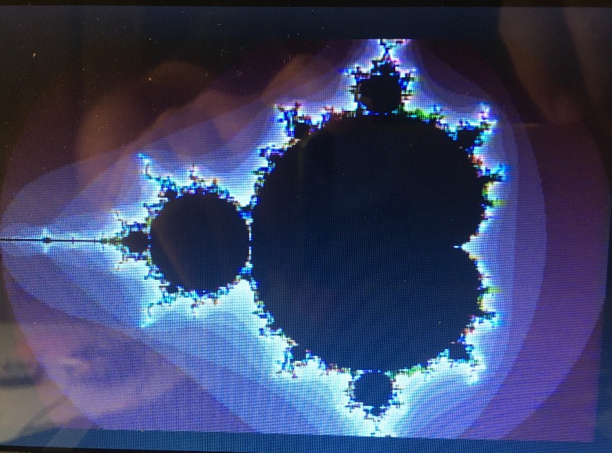
09/26/2021 at 15:47 • 0 commentsWith a display and a bunch of different Arduino/Feather boards, I figured it would be a fun little exercise to see how fast those boards would render a Mandelbrot set image with my video shield. Contestants are Arduino Uno, Mega, Due and a Feather M4 Express in NTSC320x200 and PAL300x240 resolutions. Calculations are done in float numbers for the standard number range of -2.5<x<+1 and -1<y<1. Results are rounded to the next full 0.1 second.
Board NTSC 320x200 PAL 300x240 Uno 260.5 293.1 Mega 273.5 307.8 Due 35.8 42.9 FeatherM4 1.1 1.4 And here is a bad quality demo picture of the resulting image.
![]()
The code is not optimized for speed, I have read about implementation that use only 3 multiplications instead of 6. Work for the future.
// Draw a Apfelmaennchen void Mandelbrot (byte channel, float Xn, float Xp, float Yn, float Yp){ float x0, y0, xtemp; float x = 0; float y = 0; u_int16 Px, Py; u_int16 iteration = 0; u_int16 max_iteration = 256; for (Py = 0; Py < YPIXELS; Py++){ y0 = (Yp - Yn)/YPIXELS*Py + Yn; for (Px = 0; Px < XPIXELS; Px++){ x0 = (Xp - Xn)/XPIXELS*Px + Xn; x = 0; y = 0; iteration = 0; while ((x*x + y*y <= 2*2) && (iteration < max_iteration) ) { xtemp = x*x - y*y + x0; y = 2*x*y + y0; x = xtemp; iteration++; } P42Display.SetYUVPixel (channel, Px, Py, (byte) (iteration&0xff) +0x20); } } } -
New Resolutions
08/19/2021 at 00:58 • 0 commentsThe 4x composite video output has gained new higher resolutions in the format of:
NTSC 426x200 in 256 colours
PAL 500x200 in 256 colours.
The resolutions are very unusual for 2 reasons. I was going for the highest resolution that still can display 256 colours and they are full dividers of the pixel clock to give the best quality image possible. An pixel clock divider with remainder would bleed the colour into the next pixel and one would get never twice the same color.
The code with new header files can be found under Video4 in the Github repository. The new PAL resolution does not allow for the Amiga Boing Ball demo any more, as there is not enough video memory left for the ball data.
-
Rev3 with better IO access on MEGA boards
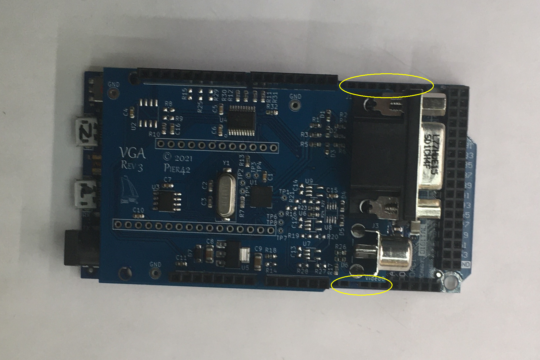
05/23/2021 at 01:14 • 0 commentsRev3 of the 4xVideo Shield with VLSI VS23S040 chip is abailable now. It is identical to the last one, just got smaller at the RCA and VGA connector end to expose the IO pin underneath when plugged into a MEGA form factor board.
-
Semi-Duplex UARTs
03/02/2021 at 02:24 • 0 commentsThe idea is to have messages from 2 serial ports being displayed and scrolled up. I would call it semi-duplex, as ideally one side sends a command/line and the the other side. If both sides send characters at the same time, they get mixed with each other in the same line. Different colours for the 2 sides are used, so it is visible if that happens.
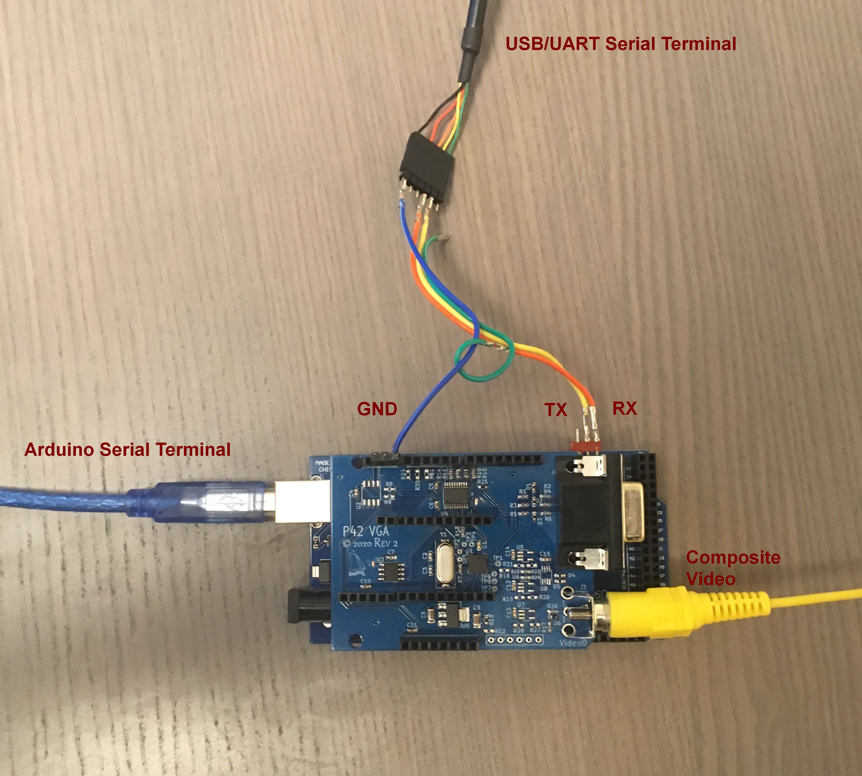
HW Setup:
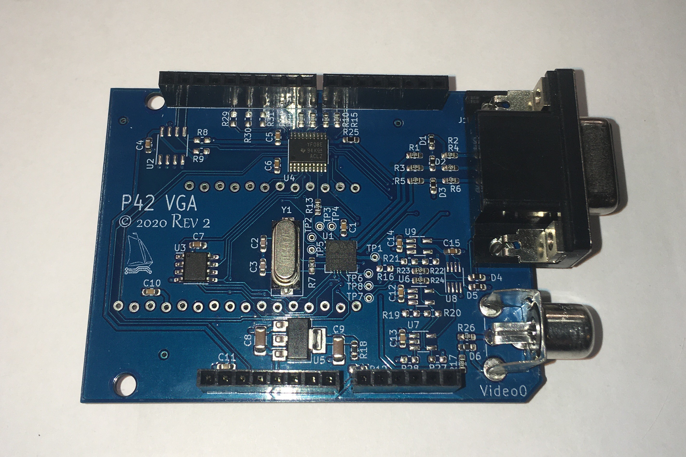
Arduino Mega with P42 Video4 VGA Shield
Standard serial port setup as SERIAL 115200 8N1
2nd serial port setup as SERIAL1 38400 8N1 (this is also a hardware serial port on the Mega on pins 18:TX 19:RX). The baudrate is set to 38400 to be operational with the Arduino SoftwareSerial library as well. For the 2nd serial port a TTl-UART adapter is required with connections to RX, TX and GND.![]()
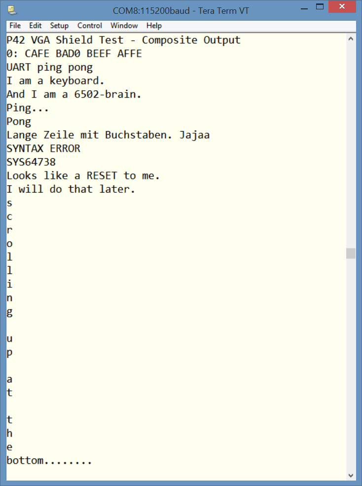
SW Setup:
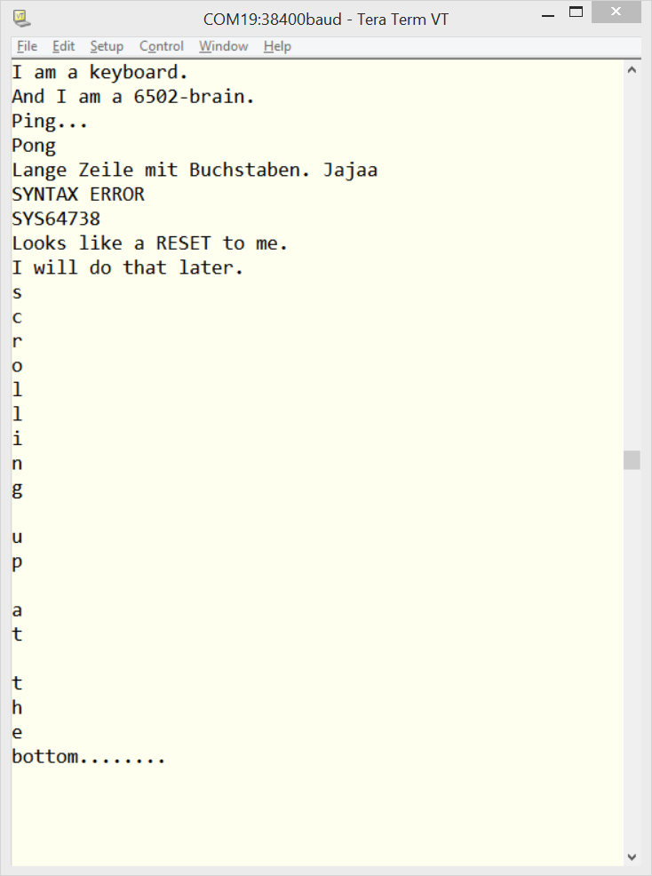
!!! The Arduino Serial Monitor is not suitable for this setup. A proper terminal software is required, I use two instances of TeraTerm, configured with the correct serial settings, local echo and transmit CR+LF.![]()
![]()
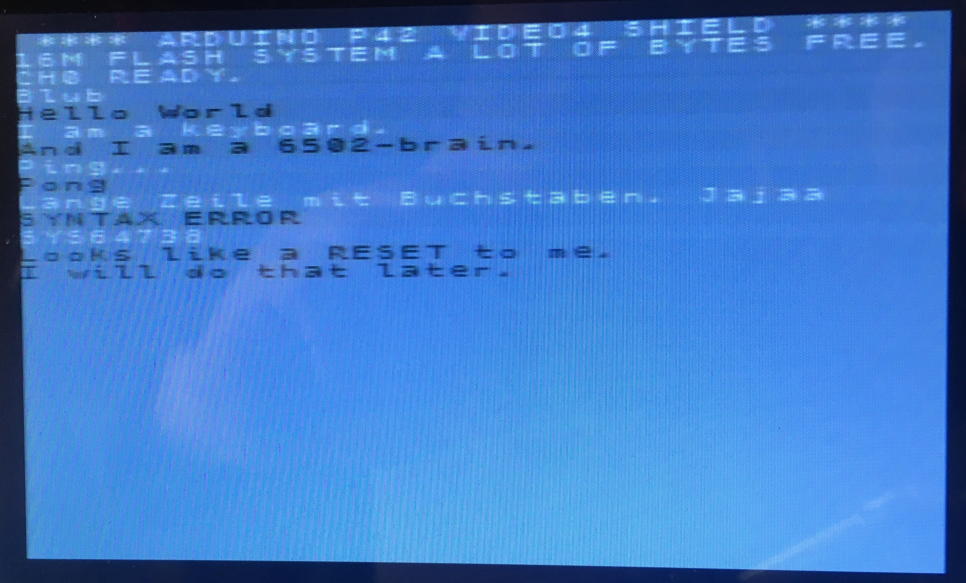
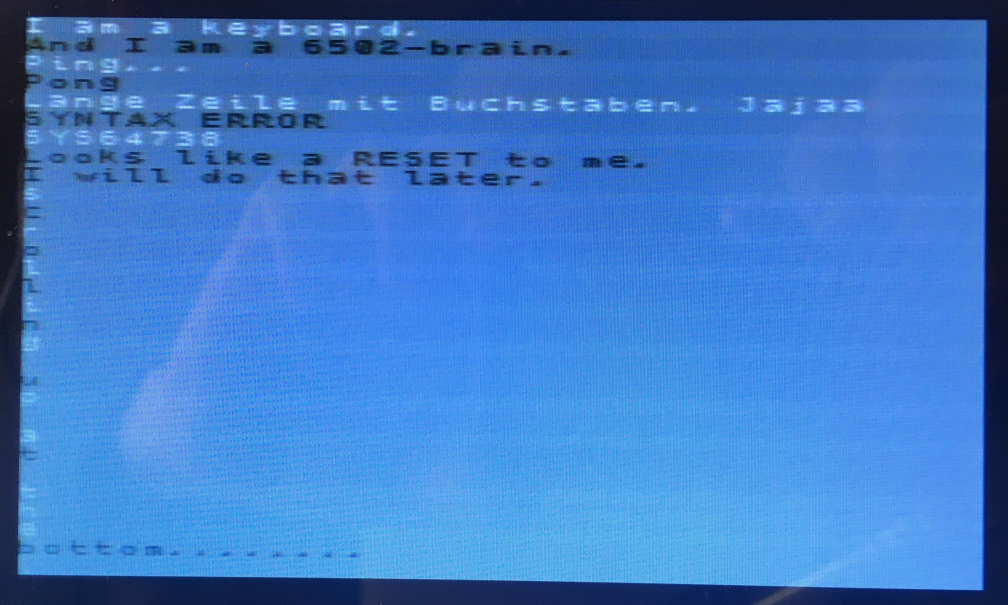
The display shows the 2 different sources in light and dark colour.
![]()
Description:
The global variables ScreenX and ScreenY as well as the function printlineXY() are the heart of this demo.ScreenX, ScreenY point to the coordinate of the screen where the next character will be printed. Function: byte printlineXY ( byte channel, char* Text, byte colour, bool ln )
Paramters:
byte channel: is the video channel used for display; can be one of CH0, CH1, CH2, CH3.
char* Text: pointer to a string, null terminated. To print a single character, the character + a NULL byte need to be content of the string. Maximum string length is the remainder of the current line + a full additional line as only one linebreak is currently implemented.
byte colour: a 8-bit colour value picked from the colour table in the user guide.
bool ln: of TRUE a CR+LF is performed to start a new line after the string got printed. byte return value: currently always 0.At the bottom of the screen, if the last line is full or LF = TRUE, a line scrolling is implemented to make room for the next line of text. Implemented control codes:
0x08 : Backspace, the last character gets deleted to free the area for the next character to be printed, so technically it is a 'delete char'
0x0A : LF Linefeed, cursor go to next line, but same horizontal position 0x0D : CR Carriage return, cursor goes to the beginning of the current line![]()
SW repository
https://github.com/wolfgangfriedrich/P42-VGA/tree/master/Code/P42VGA_V4Text -
Revision 2 is a go.
01/29/2021 at 00:57 • 4 commentsRevision 2 of the board is running as planned. I replaced the trusted level shifter buffer 74LVC4245A with a TI TXS0108, which is automatically bi-directional. The bi-dir feature is not needed here, but a good exercise for future use. Attention has to be paid, as there is also a TXB010x family which works better with fully driven signals. The TXS0108 is on order for open drain signals, e.g. the MISO sinal on SPI slave devices.
![]()
Channel 0 is on the RCA connector, channels 1,2,3 are on the VGA connector, accessible with a VGA to 3x RCA cable.
-
1st steps first
03/22/2020 at 12:53 • 0 commentsSoldering the BGA was amazingly easy. I use some low-temperature solder paste and a boatload of flux with my hot air pencil and everything aligned itself into place. How do I know that I have good contact? Measuring with a multimeter in diode mode, I see a diode drop of ~0.55V between every IO and Vcc. Now I have to solder all the other parts and start talking to the chip. Then comes the hard part, writing good driver software and config code...
The other parts went on just as easy... Well, mostly.
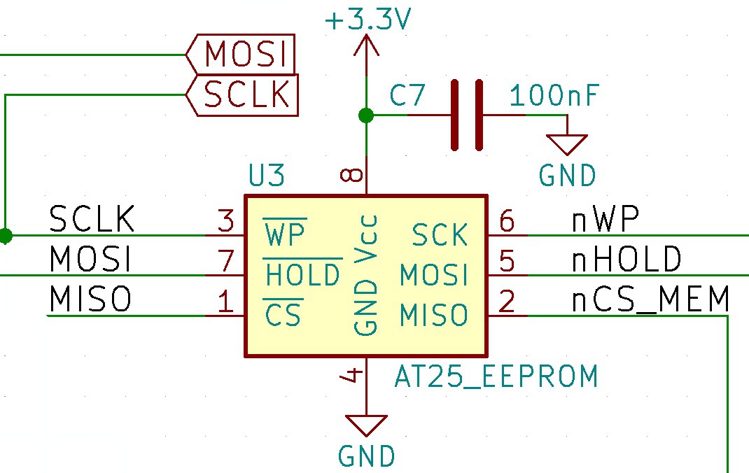
This looks like a nice schematic, all signals are there (sigh):
![]()
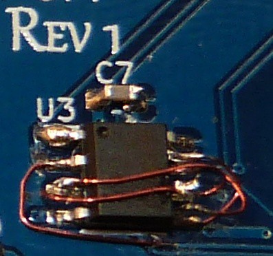
The board needed some wire surgery, but in the end it works and now I have 16Mbit of SPI Flash for character sets and images.
![]()
VGA Shield Wing
A VGA Arduino Uno Shield or Adafruit Feather Wing 640x480 - 512 colours