 Guille
-
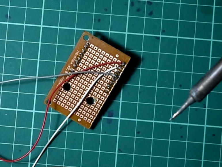
1PCB for ESP32-CAM
You need yo solders the headers to the pcb, six cables: 2 for power (VCC and GND) and four for control the stepper motor. I put small capacitor in the power connector of the ESP32-CAM.
![]()
-
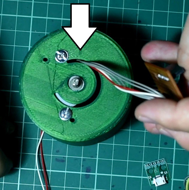
2Stepper Motor
I presented the engine in the 3D model, a mark where the screws will be. Then use the drill to make the holes.
-
3Connectios
Be sure to run the wires through the 3d piece before crimping the connectors.
![]()
-
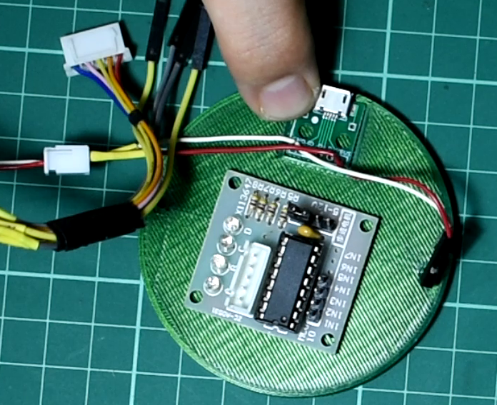
4ULN2003 and USB pcb breakout
From the usb pcb you have to have two power cables, VCC / GND for the ULN2003, and VCC / GND for the ESP32-CAM.
![]()
-
5How it work and how i made it.
Panoramic Photos with ESP32-CAM and Python
Take Panoramic Photos with ESP32-CAM and use Python to stitch multiple photo into one final.
Discussions
Become a Hackaday.io Member
Create an account to leave a comment. Already have an account? Log In.