-
Fifth release: Atari 2600
05/03/2020 at 17:34 • 0 commentsI have just uploaded the Atari 2600 firmware. It can work with
![]()
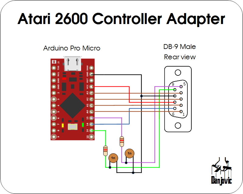
The schematic is a mix of the Sega controller with PC controller in the sense that it uses a DB-9 and two RC networks.![]()
The Driving controller uses a variable step. The faster you move it, larger are the steps.
...
// modulate the value of wheelStep to reflect the velocity that the wheel is being spinned
timeNow = millis();
deltaTime = timeNow - lastTime;
lastTime = timeNow;
  if (deltaTime < 2 )
     wheelStep = 8;
  else if (deltaTime < 6 )
     wheelStep = 4;
  else wheelStep = 1;
...
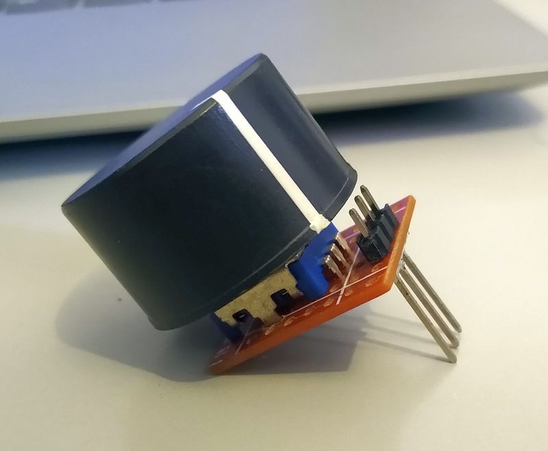
I don't have a steering controller but used an ordinary encoder to test the code.
![]()
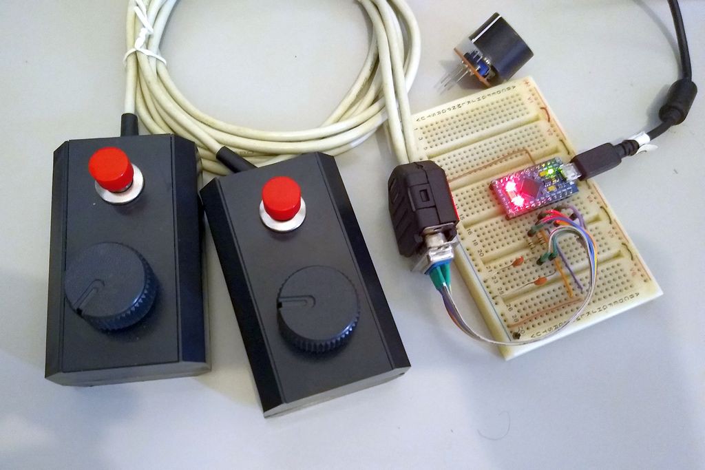
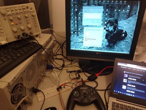
And here is the prototype. The paddles are DIY
![]()
-
Atariing
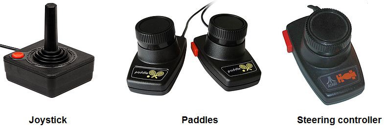
04/30/2020 at 17:03 • 0 commentsThe Atari 2600 platform provided four types of controllers:
- Joysticks
- Paddles
- Steering Controller
- Keyboard
![]()
Atari 2600 controllers (edited from a schematic borrowed from www.atariage.com) Let alone(at least by now ) the Keyboard controller it is possible to detect which type of controller we have connected by observing that:
- A joystick controller will never present (UP and DOWN) active at the same time, same apply to (LEFT and RIGHT) and both paddle readings will return in its maximum value
- An steering controller will surely present UP+DOWN at the same time during its operation
- A paddle controller will eventually present LEFT+RIGHT and will present a valid value for paddle readings.
With that in mind it is possible to fulfill the USB report using a more standardized form:
- Joystick: X and Y axes with button 1
- Steering Wheel: Axis X an button 1
- Paddle: Axes X and Y and buttons 1 and 2
The algorythm of detection can be something like:
- Sample Padddles
- if paddle values within valid range we have a paddle, goto step 5
- if UP+DOWN detected we have a driving controller, goto step 5
- if none of the conditions apply we have a joystick.
- handle the dada sampled
- do it all again
-
Yet the Sidewinder
04/23/2020 at 22:12 • 0 commentsI have made some captures of the Sidewinder controller protocol on an old desktop PC with gaming port.
![]()
It starts a handshake using all buttons and at the end falls into an operation mode where it sends the button data in 5 chunks of 3 bits on Button lines 2, 3 and 4 being clocked by button B1 line .
![]()
If no initialization is performed the controller uses only the Button 2 line to transmit data and the Button 1 line to work as a clock![]()
-
Working with SideWinder Protocol
04/22/2020 at 01:58 • 0 commentsI have a SideWinder controller that did not worked with an implementation of this protocol to V-USB (3DP-Vert) probably because my controller is Gamapad and not a force feedback joystick. I have tried to analyze the code but coudn't get too far with that. Too complex for my current skills.
![]()
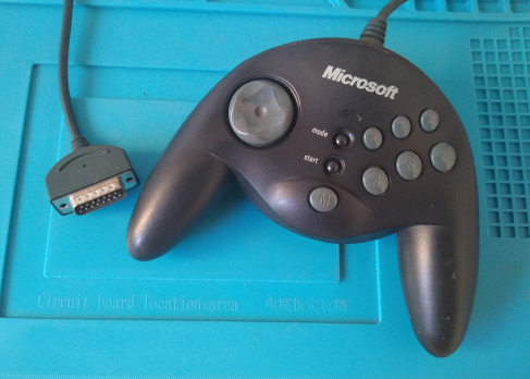
My sidewinder Gamepad I have read a more recent article about interfacing SideWinder with AVR and it was great because it pointed me to the right path, yet the code uses interrupts and it is also for a controller different from mine.
Well, having in mind the possibility to make it work also with the Digispark sidekick I have started to write my own code to read the bits coming from the joystick.
It starts to releasing the capacitors to charge and waitin for the first falling edge of the Button 1 line.
After that it starts to shift in the bits using a rudimentary state machine, and only finishes when no more data have been received after a given period.
Doing that I can receive a variable number of bits, filling up an array of bytes with the bits received.
At the end the code return the number of bits (parity bit inclusive). The code also perform the padding of the last bits just in case the count is not a multiple of 8.
Worth to mention that the code must run with interrupts disabled as the Arduino housekeeping of timers can mess with the reception of bits, but it takes mere 500us.
Well, talk is cheap, here's the code.
/* SideWinder Controller sampler function Danjovic - 21/apr/2020 */ // 125 counts to overflow @16MHz/64 = 500us #define initStopWatch() do { TIFR2 |= (1<<TOV2); TCNT2=131; } while (0) // check timer 2 overflow flag #define timeExceeded() (TIFR2 & (1<<TOV2)) // check clock line #define inputHigh() (PIND & (1<<2)) #define inputLow() !(PIND & (1<<2)) // check data line #define dataIn() !(PIND & (1<<3)) // Release capacitors to charge #define releaseCapacitors() DDRB &= ~( (1 << 0) | (1 << 1) | (1 << 2) | (1 << 3) ) #define resetCapacitors() do {DDRB|=((1<<0)|(1<<1)|(1<<2)|(1<<3)); PORTB&=~((1<<0)|(1<<1)|(1<<2)|(1<<3));} while (0) enum sideWinderStateMachine { initMachine = 0, waitStart, waitFall, waitRise, timedOut }; uint8_t sample[4]; // 64 bits can be less, can be more // // SETUP // void setup() { // Initialize Timer2 TCCR2A = (0 << WGM20) // WGM2 2..0 = 0 normal mode | (0 << WGM21) | (0 << COM2B0) | (0 << COM2B1) | (0 << COM2A0) | (0 << COM2A1); TCCR2B = (0 << CS20) // CS2 2..0 = 100 prescaler/64 | (0 << CS21) | (1 << CS22) | (0 << WGM22); TCNT2 = 0; TIFR2 |= (1 << TOV2); // clear timer flag // Pins D2..D5 as Buttons 1, 2, 3, 4 DDRD &= ~( (1 << 2) | (1 << 3) | (1 << 4) | (1 << 5) ) ; PORTD |= (1 << 2) | (1 << 3) | (1 << 4) | (1 << 5); Serial.begin(9600); Serial.println("Start"); } // // LOOP // void loop() { uint8_t i; i = sampleSideWinder(); if (i > 0 & i<128) { Serial.print("Received:"); Serial.print(i); Serial.print(" buttons"); for (i=0;i < sizeof(sample); i++) { Serial.print (" "); Serial.print (sample[i],BIN); } Serial.println(); } else Serial.println("fail"); delay(5); } // // Sample SideWinder controller. Can receive multiple bytes // uint16_t sampleSideWinder() { uint8_t shiftRegister; uint8_t index; uint8_t bitCount; uint8_t parityCount; uint8_t state=initMachine; uint8_t bufferFull; uint8_t i; // Interrupts must be turned off so Arduino timer housekeeping // do not interfere with data stream timing cli(); releaseCapacitors(); // State machine to receive data stream in bytes do { switch (state) { case initMachine: shiftRegister = 0; index = 0; bitCount = 0; parityCount = 0; state= 0; bufferFull = 0; initStopWatch(); // timeout at 600us state = waitStart; break; case waitStart: // wait for the first falling edge if (inputLow()) { state = waitRise; } break; case waitFall: if (inputLow()) { state = waitRise; sample[index] = shiftRegister; if ((bitCount&0x07) == 0) { // 3 LSBit goes zero every 8th bit received shiftRegister = 0; index++; if (index>=sizeof(sample)) bufferFull=1; } } break; case waitRise: if (inputHigh()) { shiftRegister <<= 1; if (dataIn()) { shiftRegister |= 1; parityCount++; } bitCount++; state = waitFall; } break; } //switch } while (!timeExceeded() & !bufferFull); resetCapacitors(); sei(); // Justify last bits received to left (padding) i = (bitCount & 0x07); while (i<8) { sample[index]<<=1; i++; } // parityCount should be an Odd number // return bit 7 of bitCount set if parity check fails. return ( (bitCount & 0x7f) | (~parityCount<<7) ); } -
Fourth Release: The Attack of cloNES
04/18/2020 at 18:34 • 0 commentsThere is a lot of NES/SNES controler adapter projects availabe online, and I even have built myself one ( #Digi:[S]NES ).
The code is very straightforward:
- Pulse the latch line
- Read a bit
- Pulse the clock
- Repeat step 2 until you have read 12 bits
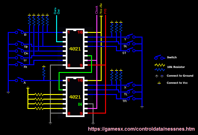
NES and SNES controller protocol The same code can be used for NES and SNES, with one minor inconvenience that the buttons A and B are not on the same position in either controller, meaning that the buttons assigned to B and Y will be activated when a NES controller is plugged.
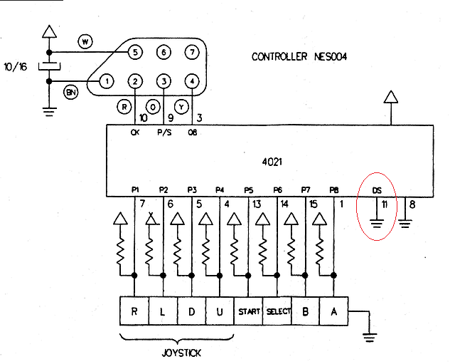
The code that I have has been proven on several NES controllers that I have but none of them were original controllers.According to the schematics of the NES controllers that I have found online that shouldn't happen (quite right) because the NES controller is based on a 4021 shift register chip which have the SHIFT IN pin connected to GND (that was done by Nintendo to provide means to detect the presence of the controller).
NES controller schematic
But the Knockoffs that I have always present a HIGH after the last button read (RIGHT)Waveform for the Knockoff NES controller
Ok, that is a good effect of using knockoffs but I want this firmware to be ready to use original controllers, and I wish also to have A and B mapped to the same (PC) buttons, no matter if a NES or an SNES controller is attached. For accomplishing that I need to differentiate the SNES controller from the NES controller (and from the Knockoffs).
The solution came from the analysis of the SNES controller schematic. It uses two 4021s in series and also have the serial input of the last shift register connected to the GND and the last bits (which are unused) are pulled up to VCC. Tha means that after the 12 button bits I should have 4 bits HIGH and after that any bit read will be LOW.
So considering the complete waveform, we can read 17 bits from the controller then analyze the last 5 bits received:- if last 5 bits are 01111 then we have a SNES controller
- if last 5 bits are 00000 then we have a NES controller
- anything different we have a knockoff controller and it will be treated as a NES controller
The code is implemented slightly different because I use a 16 bit variable for the shifted bits and after all bits are shifted in I test the 17th bit, and test for 8 bits in LOW for the NES controller.
  // read 16 bits from the controller
  dataIn = 0;
  for (i = 0; i < 16; i++) {
    dataIn >>= 1;
    if (digitalRead(dataPin)==0) dataIn |= (1<<15) ; // shift in one bit
    Pulse_clock();
  }

  if (digitalRead(dataPin)) { // 17th bit should be a zero if an original controller is attached
    controllerType = NONE;
  } else {
    if ( (dataIn & 0xf000) == 0x0000)
      controllerType = SNES;
    else  if ( (dataIn & 0xff00) == 0xff00)
      controllerType = NES;
     else
       controllerType = NONE;
      }
Luckly the knockof SNES controller that I have worked as expected. As the SNES uses the last bits to identify some different types of controllers like the mouse, I thinkg that the knockoff manufacurers took care in following the behaviour or the original controller.
Here's a waveform for the SNES controller.
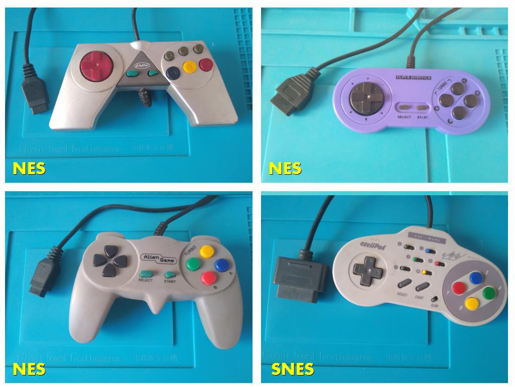
And that concludes the fourth release. I left below a montage with my knockoffs:![]()
-
Third Release: SEGA Controllers
04/16/2020 at 22:39 • 0 commentsNothing more appropriate to this third release than a firmware that can handle 3 controllers:
![]()
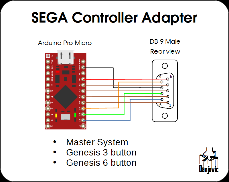
The firmware can work with either controller and will report buttons in the following sequence:
Mapped Button Genesis 6 button Genesis 3 button Master System 1 A A 1 2 B B 2 3 C C 4 X 5 Y 6 Z 7 START START 8 MODE Besides the Arduino Micro, only one component is required: A DB-9 male connector:
SEGA controller adapter schematic
The prototype was assembled on a proto-board:![]()
Identifying the controllers
The basic controller is the Master system controller that uses 6 rubber keys to deliver a D-Pad and a couple of buttons. Nothing unusual to notice here except that most of the lines of the DB-9 controller are occupied, as the Master System joystick port have a +5V and a GND line, adding up to a total of 8 out of 9 lines being used.
The Sega Genesis used the same DB-9 connector for the joystick port to maintain compatibility with the former controllers the new controller have more buttons than available lines (D-Pad plus 4 buttons: A, B, C and START). The solution adopted by SEGA was to use the remaining line to command a Multiplexer thus providing the twice times the number of lines, but that was not so easy as one problem left: How do the games would differentiate which button is which when a Master system controller was connected? Again the solution was simple. When a Genesis controller is connected and the selection line is unactive (low) then both Left and Right directions would be active at the same time, and that is a condition than would never occur on a Master System controller given the mechanical design of the D-Pad cross.Pin: 9 6 4 3 2 1 Sel=0 ST A 0 0 DW UP Sel=1 C B RG LF DW UP
When the 6 button controller was introduced a similar problem showed up and this time the solution adopted was very peculiar. Another Mux was added inside the controller for the extra buttons and the control of such Mux is triggered by a counter that in turn is activated by the "Select" Line. After the third edge the extra mux is activated and the buttons X, Y, Z and MODE are present on the data lines. But one problem left (again). How to synchronize the game code with the pulse count? Simply counting the pulses issue is out of question since the controller can be inserted and removed while the game is running.The solution for the six button controller used two mechanisms:
The first is to generate another invalid pattern, this time with all directionals activated at the same time right before the extra buttons ( X, Y, Z, MODE) are ready to be read. Additionally, all the directionals are deactivated on the next edge after the extra buttons are read so the game can differentiate between the "all directionals activated" from "all extra buttons activated".
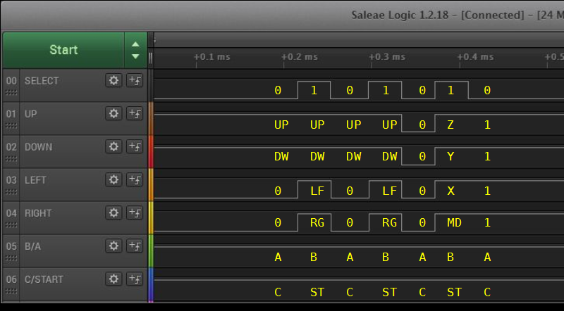
Pin: 9 6 4 3 2 1 Sel=0 ST A 0 0 DW UP Sel=1 C B RG LF DW UP Sel=0 ST A 0 0 DW UP Sel=1 C B RG LF DW UP Sel=0 ST A 0 0 0 0 -> Directionals LOW right before extra buttons Sel=1 1 1 MD X Y Z 3rd rising edge Sel=0 ST A 1 1 1 1 -> Directionals HIGH right after the extra buttons
Data capture for 6 button controller
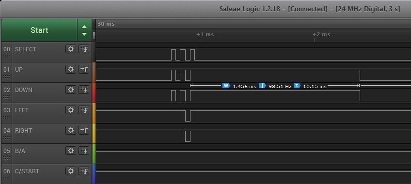
The second mechanism is a timeout. It the Select line do not change state again within ~1.5ms then the internal counter is reset.![]()
Timeout for a genuine sega controller ![]()
Timeout for a clone controller The code performs a series of samples and checks the state of the unique conditions to identify whether the controller is a 3 button or a 6 button controller. If neither one is identified the code assumes that the controller is a Master System (or unknown)
uint8_t SEGAscan(void) {
  uint8_t sample[7];
  uint8_t type;
  combinedButtons = 0;

  sample[0] = readController();   //  ST A  0  0  DW UP

  digitalWrite(genesisSelect,HIGH);
  sample[1] = readController();   //  C  B  RG LF DW UP

  digitalWrite(genesisSelect,LOW);
  sample[2] = readController();   //  ST A  0  0  DW UP

  digitalWrite(genesisSelect,HIGH);
  sample[3] = readController();  C  B  RG LF DW UP

  digitalWrite(genesisSelect,LOW);   //
  sample[4] = readController();  ST A  0  0  0  0

  digitalWrite(genesisSelect,HIGH);
  sample[5] =  readController();  //  1  1  MD X  Y  Z

  digitalWrite(genesisSelect,LOW);
  sample[6] = readController();   //  ST A  1  1  1  1

  // check for 3 or 6 buttons
  if ( ((sample[4] & 0x03) == 0) && ((sample[6] & 0x0f)==0x0f) ) {
     type = _6Button;
  } else if  ( (sample[6] & 0x0c) == 0)  {
     type = _3Button;
  } else
     type = _unKnown;
...
...
}
The rest of the code uses sampled data to form a 16 bit word with the state of all buttons, as applicable to the type of controller.
  // now populate combinedButtons variable accordingly       // 15 14 13 12 11 10 9  8  7  6  5  4  3  2  1  0
  combinedButtons = (uint16_t)sample[1];                     // 0  0  0  0  0  0  0  0  0  0  C  B  RG LF DW UP
  combinedButtons |= ((uint16_t)(sample[0]<<2)) & 0xc0;      // 0  0  0  0  0  0  0  0  ST A  C  B  RG LF DW UP
  combinedButtons |= ((uint16_t)(sample[5]<<8)) & 0xf00;     // 0  0  0  0  MD X  Y  Z  ST A  C  B  RG LF DW UP
...
  // invert bits. Make '1' the active state
  combinedButtons = ~combinedButtons;
  switch (type) {
    case _6Button:
      combinedButtons &= 0x0fff;
      break;
    case _3Button:
      combinedButtons &= 0x00ff;
    default:
      combinedButtons &= 0x003f;
    }
And that concludes the third release.
-
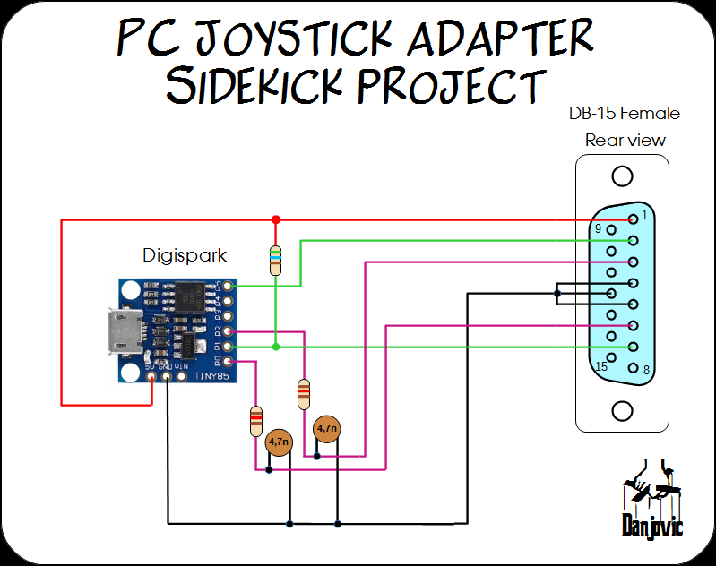
Sidekick Project: PC joystick with Digispark
04/15/2020 at 17:22 • 0 commentsThe oldest PC joysticks only provide a pair of axis (X-Y) and two buttons and the USB adapter for such can be implemented using a cheaper boarf: The Digispark.
Further details are provided on a separate page
-
Minor Updates
04/14/2020 at 02:15 • 0 commentsMinor updates on the versions released so far.
- PC Joystick
The circuit can read up to 4 axes, but most of joysticks of that era only implements 2 or 3. Then whenever a potentiometer is not connected the value reported will be around the middle of the scale which means 200 counts for the standard 100K potentiometer.
Worth to remember that the circuit shall provide useful range for potentiometers up to 250k Ohms (around 1000 counts)
... // Take care of disconnected axes if (a1X == maxCounts ) a1X=midRange; if (a1Y == maxCounts ) a1Y=midRange; if (a2X == maxCounts ) a2X=midRange; if (a2Y == maxCounts ) a2Y=midRange; ...- Foot Pedal
Now the firmware can detect when a footpedal is not connected and does not report any key instead of report the they R continuously pressed.
void loop() { sampleAnalogAxes(); if (a1Y < 100) { // Brake presse Keyboard.press(KEY_V); } else if (a1Y > 600) { // Pedal Not connected Keyboard.releaseAll(); } else if (a1Y > 300) { // Gas pressed Keyboard.press(KEY_R); } else { Keyboard.releaseAll(); } ..... } -
Second Release - Foot Keyboard
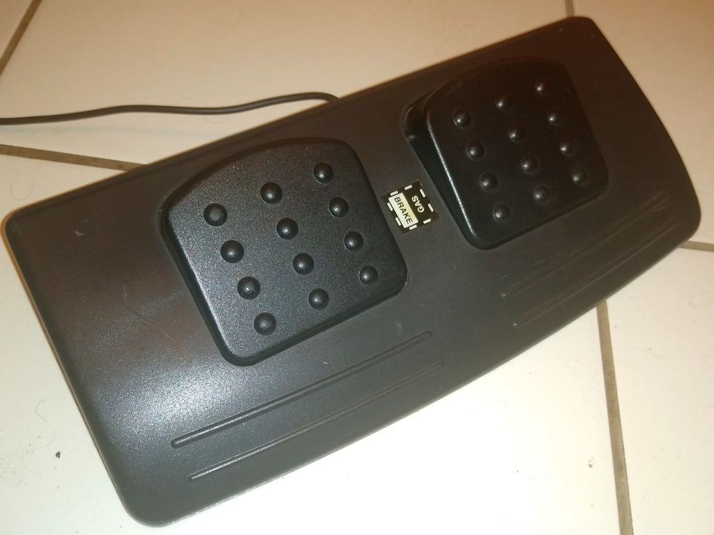
04/13/2020 at 01:21 • 0 commentsI have this nice foot controller for PC game port acquired by a bargain at a recycle facility.
![]()
It is composed of a single axis that can be used either as a Gas/Brake for a racing game or as a Left/Right rudder control.
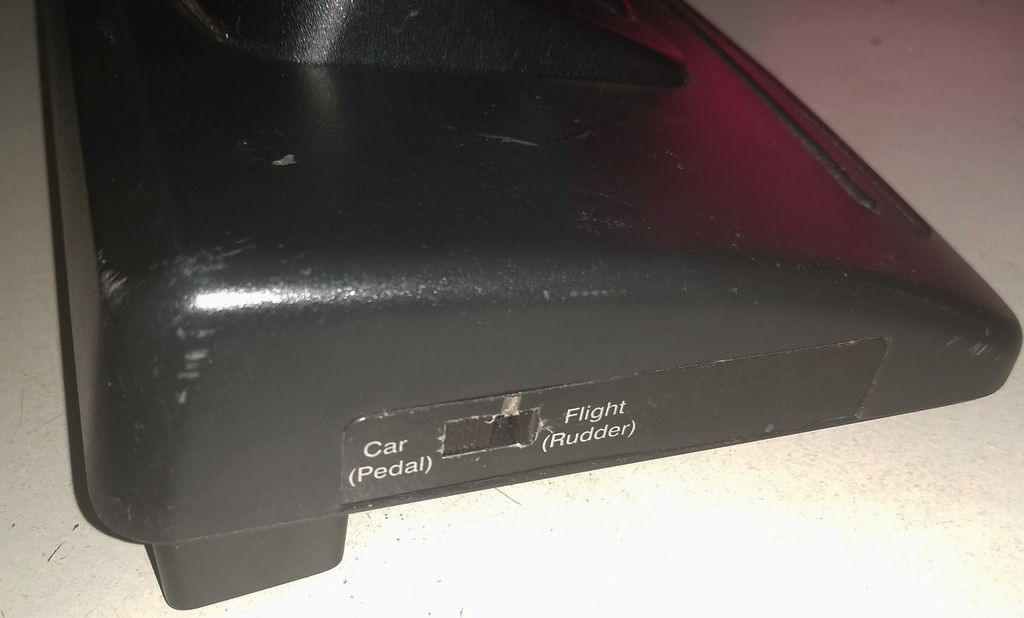
The selection of either mode is done by a switch at the side of the base. When in Car (Pedal) positon the potentiometer is attached to the Y1 axis of the joystick port. On the other hand while in Flight (Rudder) mode the pot is attached to the X2 axis.
![]()
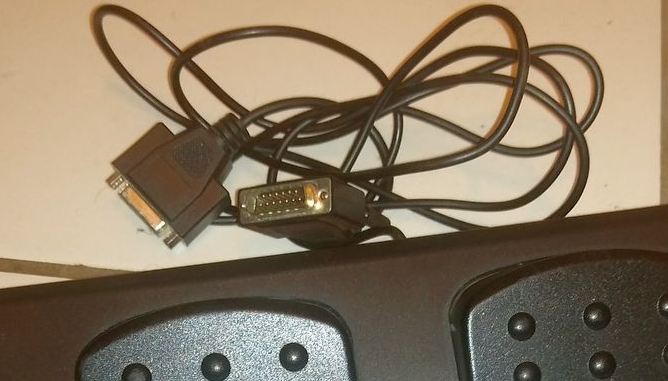
The cable of this foot controller have a a pass-through connector that is specially intended to work in Flight mode to provide Rudder axis to an ordinary Joystick.
I have used a foot pedal for FPS games in a former project ( #F.P.S: Foot Presto Switch ) and decided to write a firmware and it worked great.
The second release for this project is then a Foot Keyboard, this time with 2 keys. It uses the same schematic as the base PC joystick (it can be simplified though)
In this firmware we use the Keyboard object (instead of Gameport).void setup() { .... Keyboard.begin(); ..... }
And the main loop simply reads the X1 axis (mode switch should be CAR) to check if either one of the pedals is pushed and keep a keyboard key code active until the pedal is released.
When no pedal is pushed (or if both are) then the firmware call the method ReleaseAll( ) to tell the PC that no key is active anymore.
Using the Arduino Micro the range of the Axes for a 100k potentiometer shall be within the range 0..400 approximately.The thresholds of 100 and 300 are thus the end of the first quarter and the beginning of the third quarter of the reading value.
Such thresholds provided a comfortable use. I can left my feet rest on the top of the pedals without unintended triggering, but the thresholds can me modified to be closer to the middle of the scale (200) and then provide more sensibility.
And last but not least the code is mapping the keys R and V but that of course can be modified in the code or reconfigured in the game.
void loop() {
  // Update Analog Axes
  sampleAnalogAxes();

  if (a1Y < 100) { // Brake presse
    Keyboard.press(KEY_V);
  } else if (a1Y > 300) { // Gas pressed
    Keyboard.press(KEY_R);
  } else {
    Keyboard.releaseAll();
  }

  // Simple debounce
  delay(10);
}
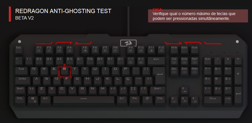
The circuit can be tested using an online keyboard test utility.
Source code is available on Github. -
First release - Basic PC joystick
04/12/2020 at 22:53 • 2 commentsFirst release is working. Source code is available at the project repository.
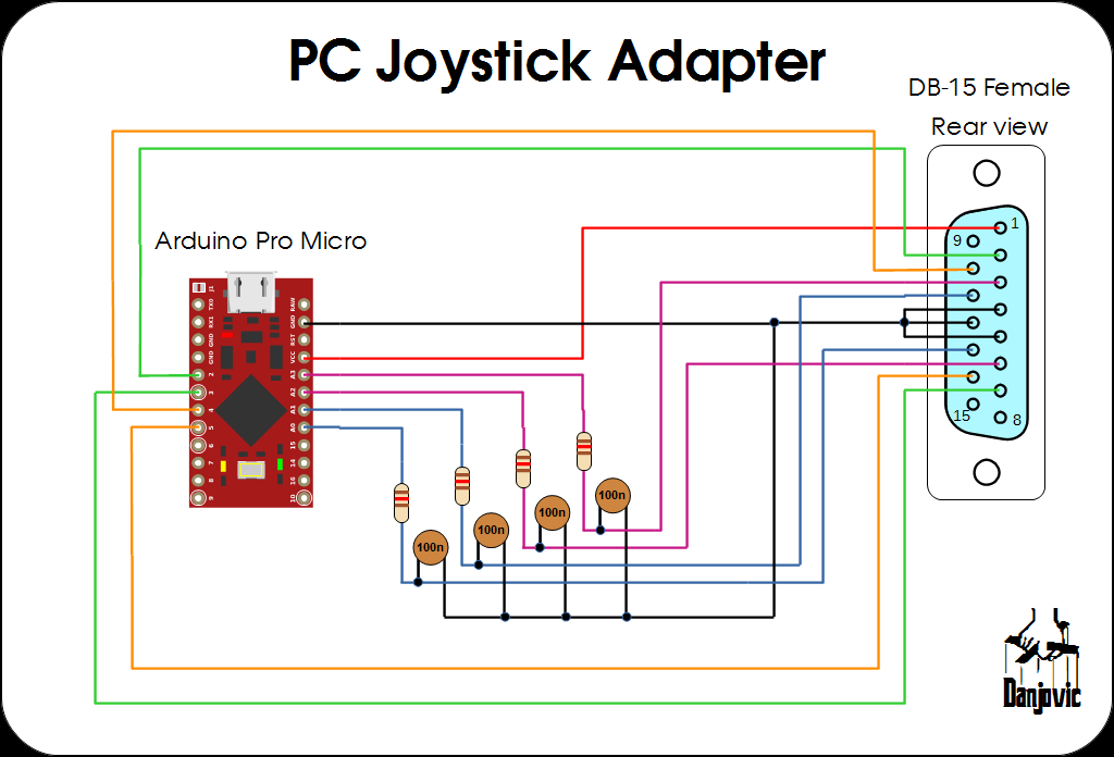
PC Joystick adapter schematics
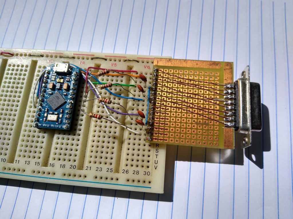
And the prototype was assembled on a proto-board.![]()
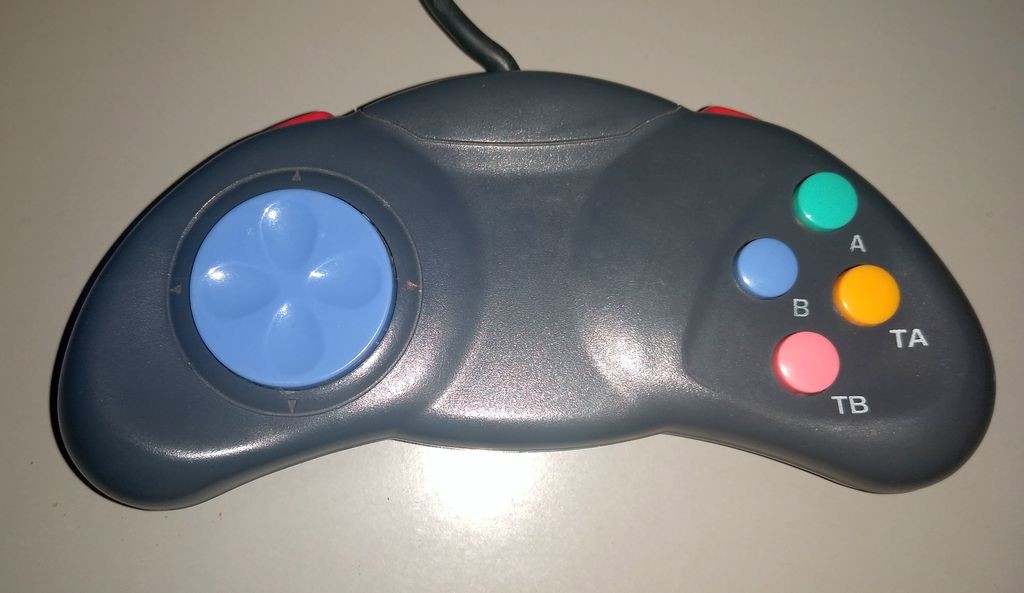
And the first controller integrated to the project is a boomerang PC gamepad by unknown manufacturer.The D-Pad provides discrete resistances on X and Y axes (0, ~50k, ~100k).
Buttons A and B have a TURBO function and are mapped to buttons 1 and 2 of the Joystick 1 (pins 2 and 7).
Shoulder buttons Right and Left are mapped to buttons 1 and 2 of the Joystick 2 (pins 10 and 14).
![]()
Control Freak
Collection of Arduino Micro firmware and schematics for connecting your retro Joysticks and Gamepads to USB port.
 danjovic