 Angeliki Beyko
-
1Neopixel Strip - Setup and Testing
![]()
Following this tutorial on Adafruit, test that the circuit for the led strip is working.
This is my modified code for this circuit so far:
// Simple NeoPixel test.  Lights just a few pixels at a time so a
// 1m strip can safely be powered from Arduino 5V pin.  Arduino
// may nonetheless hiccup when LEDs are first connected and not
// accept code.  So upload code first, unplug USB, connect pixels
// to GND FIRST, then +5V and digital pin 6, then re-plug USB.
// A working strip will show a few pixels moving down the line,
// cycling between red, green and blue.  If you get no response,
// might be connected to wrong end of strip (the end wires, if
// any, are no indication -- look instead for the data direction
// arrows printed on the strip).

#include

#define PIN      6
#define N_LEDS 136

Adafruit_NeoPixel strip = Adafruit_NeoPixel(N_LEDS, PIN, NEO_GRB + NEO_KHZ800);

void setup() {
  strip.begin();
}

void loop() {
  chase(strip.Color(255, 0, 0)); // Red
  chase(strip.Color(0, 255, 0)); // Green
  chase(strip.Color(0, 0, 255)); // Blue
}

static void chase(uint32_t c) {
  for(uint16_t i=0; i4; i++) {
      strip.setPixelColor(i  , c); // Draw new pixel
      strip.setPixelColor(i-4, 0); // Erase pixel a few steps back
      strip.show();
      delay(25);
  }
}
Here is a video of what the LEDs should look like when plugged into power, after you upload the code to the Arduino Mega:
-
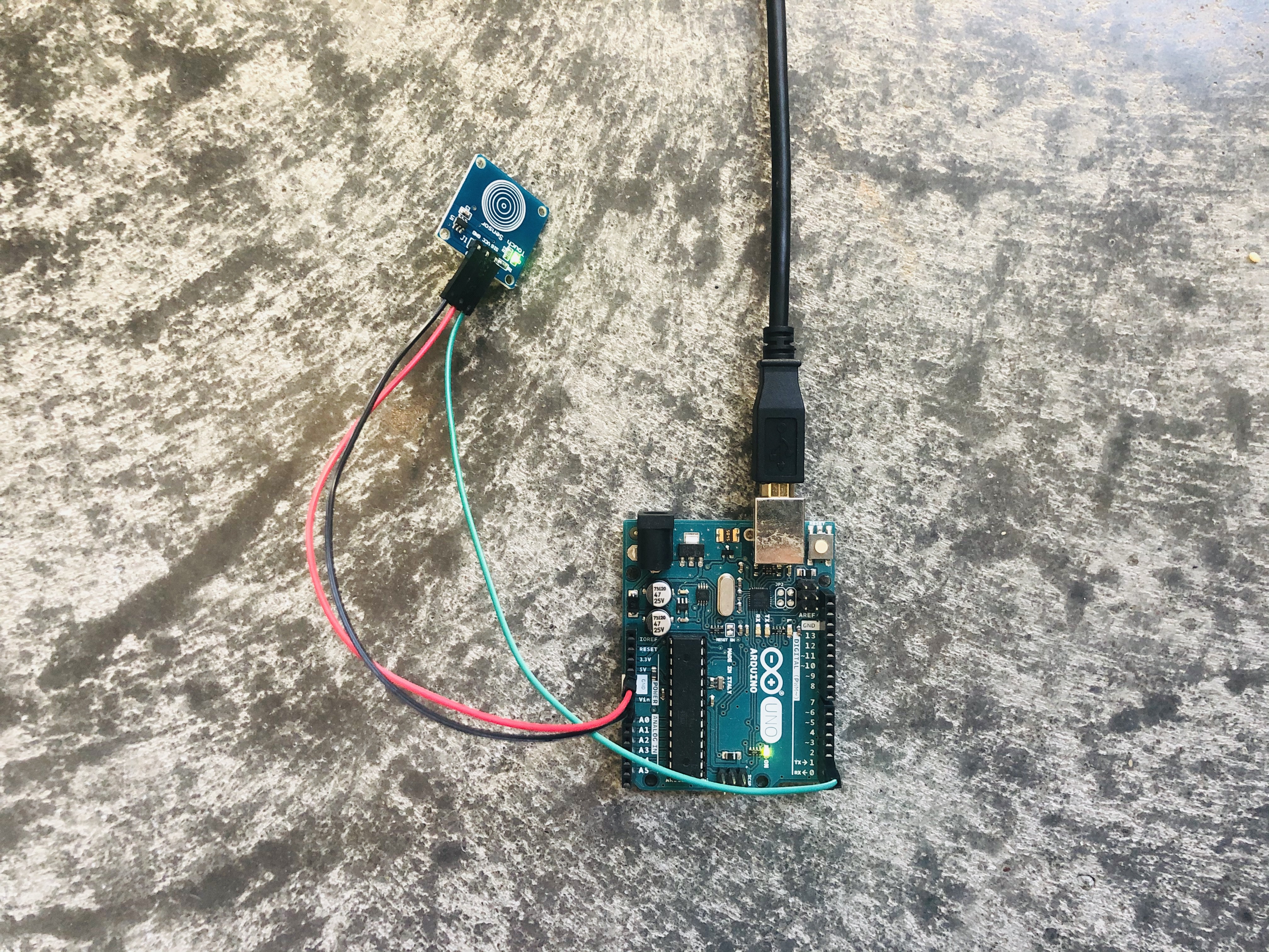
2Capacitive Touch Sensor Modules - Setup and Testing
![]()
Code for testing the capacitive touch sensor module below:
#define touchPin 2

int ledPin = 13;

void setup() {
  Serial.begin(9600);
  pinMode(ledPin, OUTPUT);
  pinMode(touchPin, INPUT);
}

void loop() {
  int touchValue = digitalRead(touchPin);
  if (touchValue == HIGH) {
    Serial.println("TOUCHED");
    digitalWrite(ledPin, HIGH);
  } else {
    digitalWrite(ledPin, LOW);
  }
  delay(350);
}
Video demo:
-
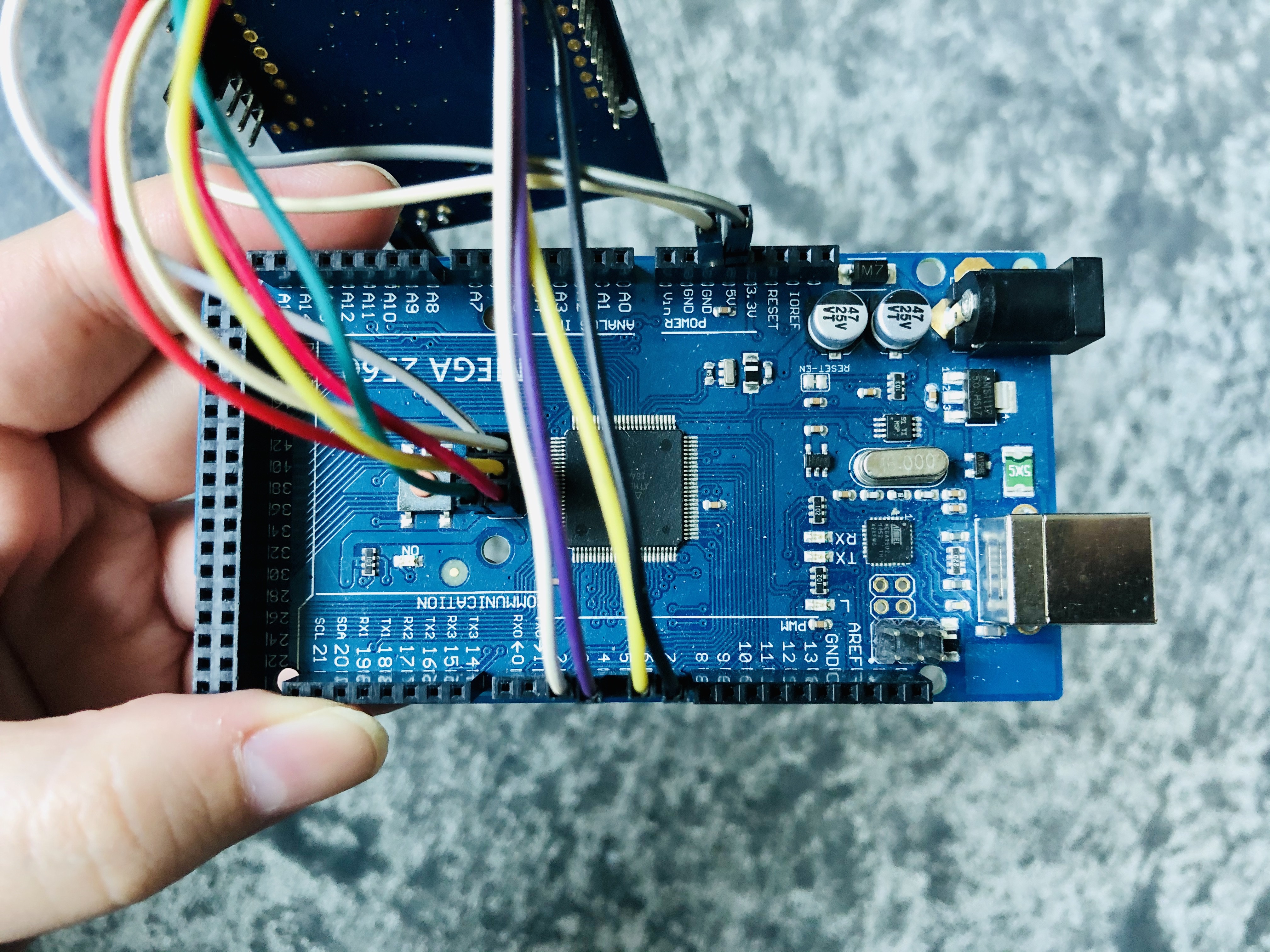
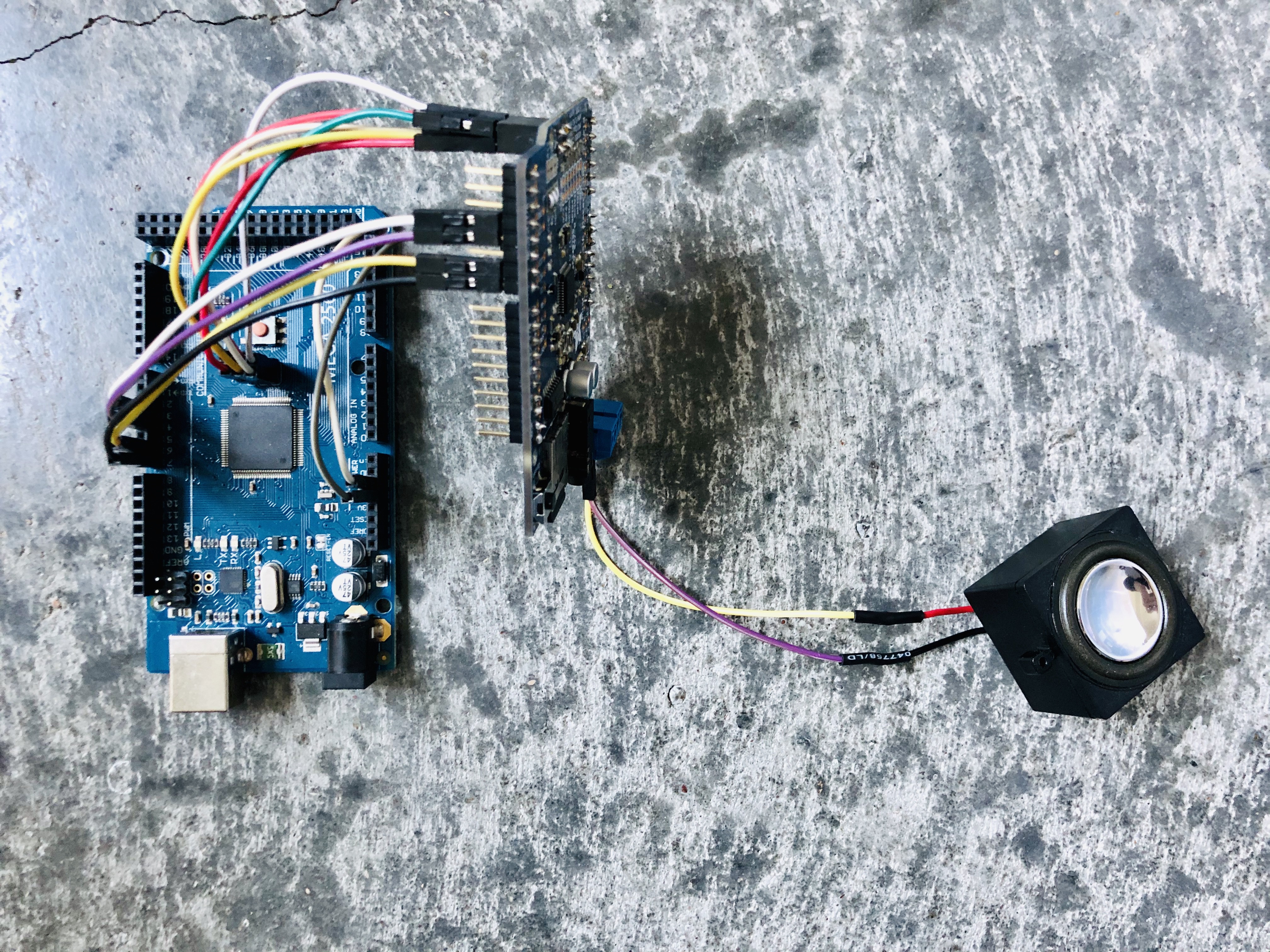
3Music Maker MP3 Shield - Setup and Testing
![]()
![]()
![]()
Code below modified from player_simple example under the VS1053 library examples. Instructions on how to find this are here:
Note: Your music player files that are stored on your SD card must follow a 8.3 format. That is: up to 8 characters max, followed by a dot, followed by a 3 letter extension. For example: "track001.mp3".
/***************************************************
  This is an example for the Adafruit VS1053 Codec Breakout

  Designed specifically to work with the Adafruit VS1053 Codec Breakout
  ----> https://www.adafruit.com/products/1381

  Adafruit invests time and resources providing this open source code,
  please support Adafruit and open-source hardware by purchasing
  products from Adafruit!

  Written by Limor Fried/Ladyada for Adafruit Industries.
  BSD license, all text above must be included in any redistribution
 ****************************************************/

// include SPI, MP3 and SD libraries
#include
#include
#include

// These are the pins used for the music maker shield
#define SHIELD_RESET  -1      // VS1053 reset pin (unused!)
#define SHIELD_CS     7      // VS1053 chip select pin (output)
#define SHIELD_DCS    6      // VS1053 Data/command select pin (output)

// These are common pins between breakout and shield
#define CARDCS 4     // Card chip select pin
#define DREQ 3       // VS1053 Data request, ideally an Interrupt pin

Adafruit_VS1053_FilePlayer musicPlayer =
  Adafruit_VS1053_FilePlayer(SHIELD_RESET, SHIELD_CS, SHIELD_DCS, DREQ, CARDCS);

void setup() {
  Serial.begin(9600);
  Serial.println("Adafruit VS1053 Simple Test");

  if (! musicPlayer.begin()) { // initialise the music player
     Serial.println(F("Couldn't find VS1053, do you have the right pins defined?"));
     while (1);
  }

  Serial.println(F("VS1053 found"));

   if (!SD.begin(CARDCS)) {
    Serial.println(F("SD failed, or not present"));
    while (1);  // don't do anything more
  }

  // Set volume for left, right channels. lower numbers == louder volume!
  musicPlayer.setVolume(1,1);
}

void loop() {
  Serial.println(F("Playing pro00001"));
  musicPlayer.playFullFile("prompts/pro00001.mp3");
  delay(1000);
}
There is some extra soldering you have to do, to play music on the music maker mp3 shield by Adafruit on the Arduino Mega 2560. Basically you want to solder across the ICSP jumpers on the shield. See link below for more info and instructions:
https://learn.adafruit.com/adafruit-music-maker-shield-vs1053-mp3-wav-wave-ogg-vorbis-player/pinouts
In the files section of this project, you can find all 96 greek word recordings (12 recordings for each of the 8 categories).
-
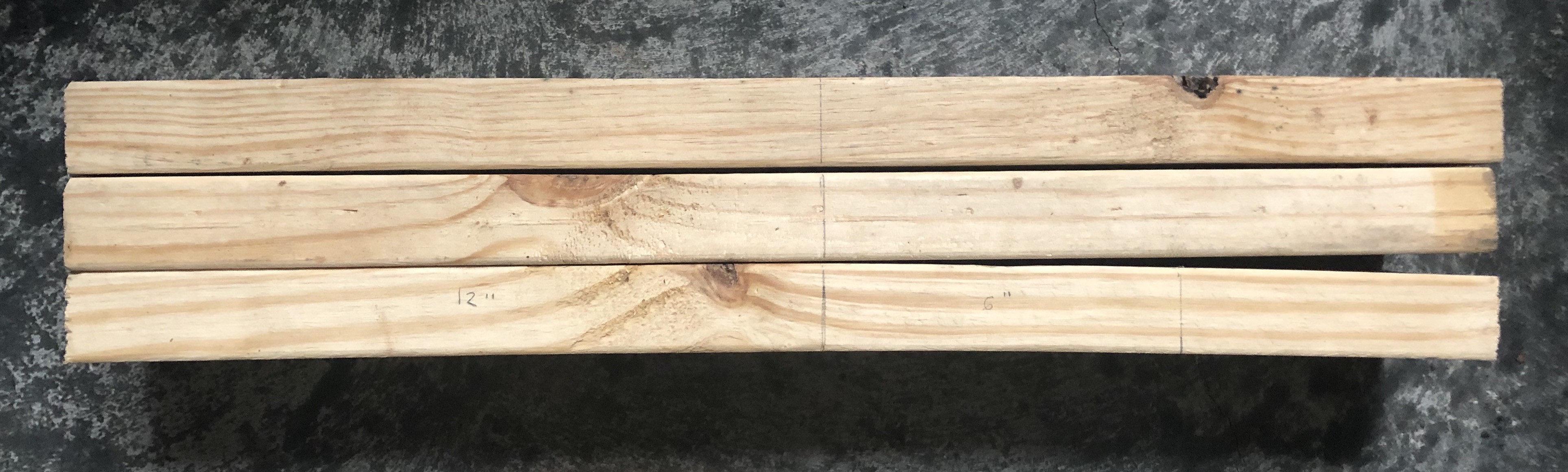
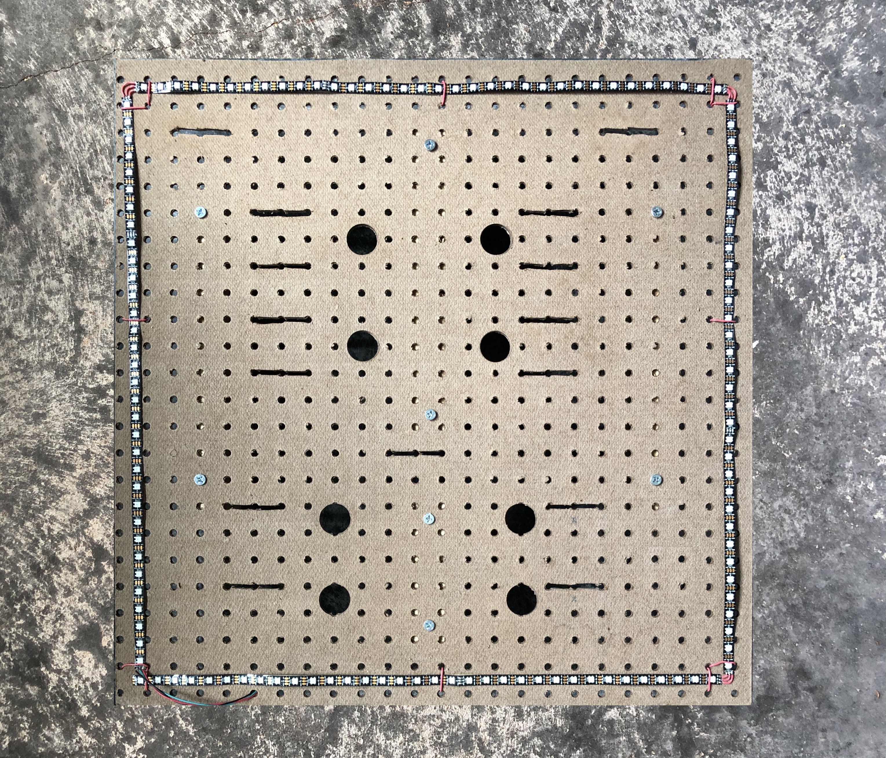
4Board Woodworking - In Preparation for Next Steps
When the arcade buttons are mounted into the peg board, they need clearance underneath for the part of the button containing the spring. The button is approximately 2 " tall and requires room for the wiring in addition.
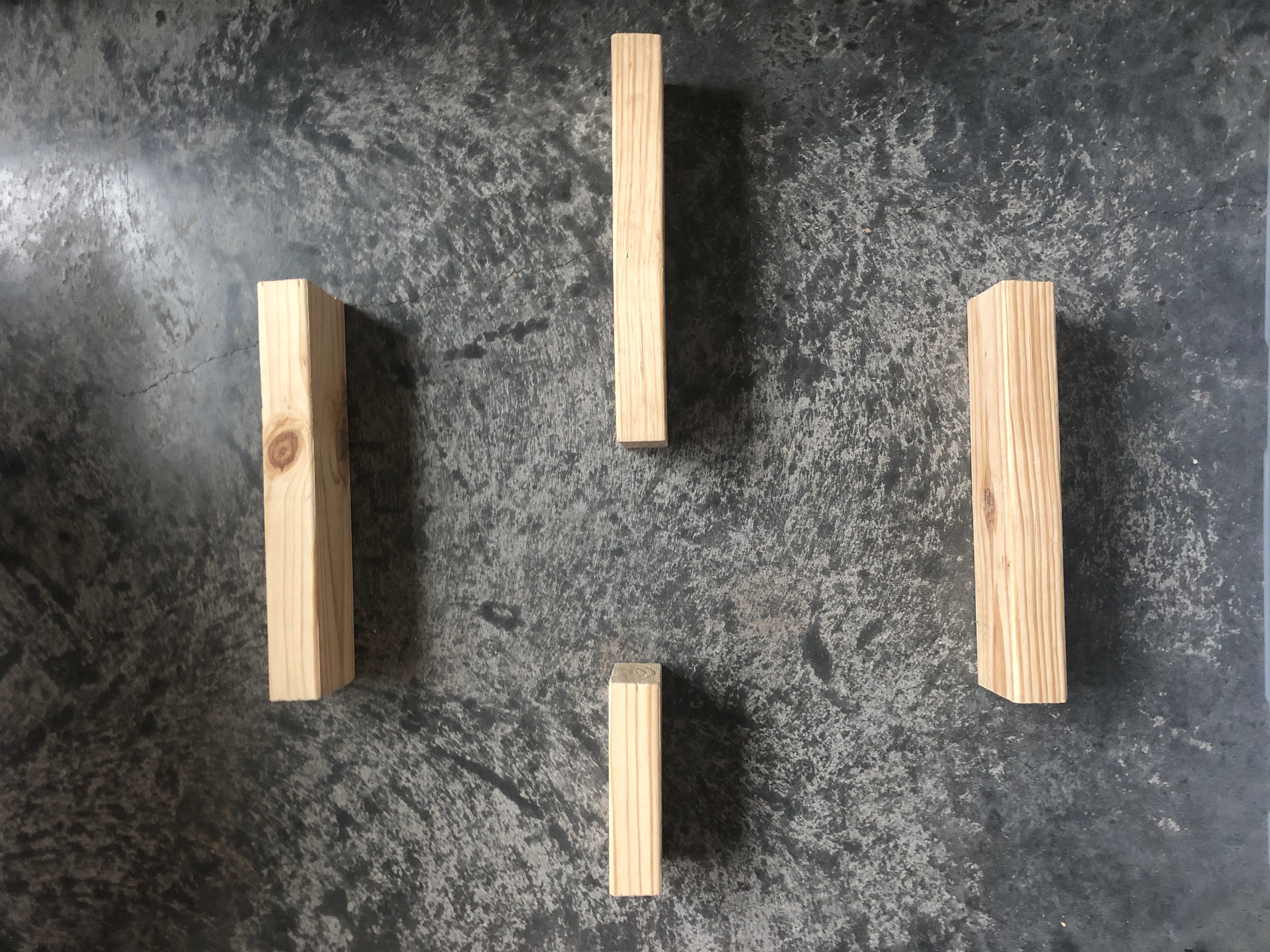
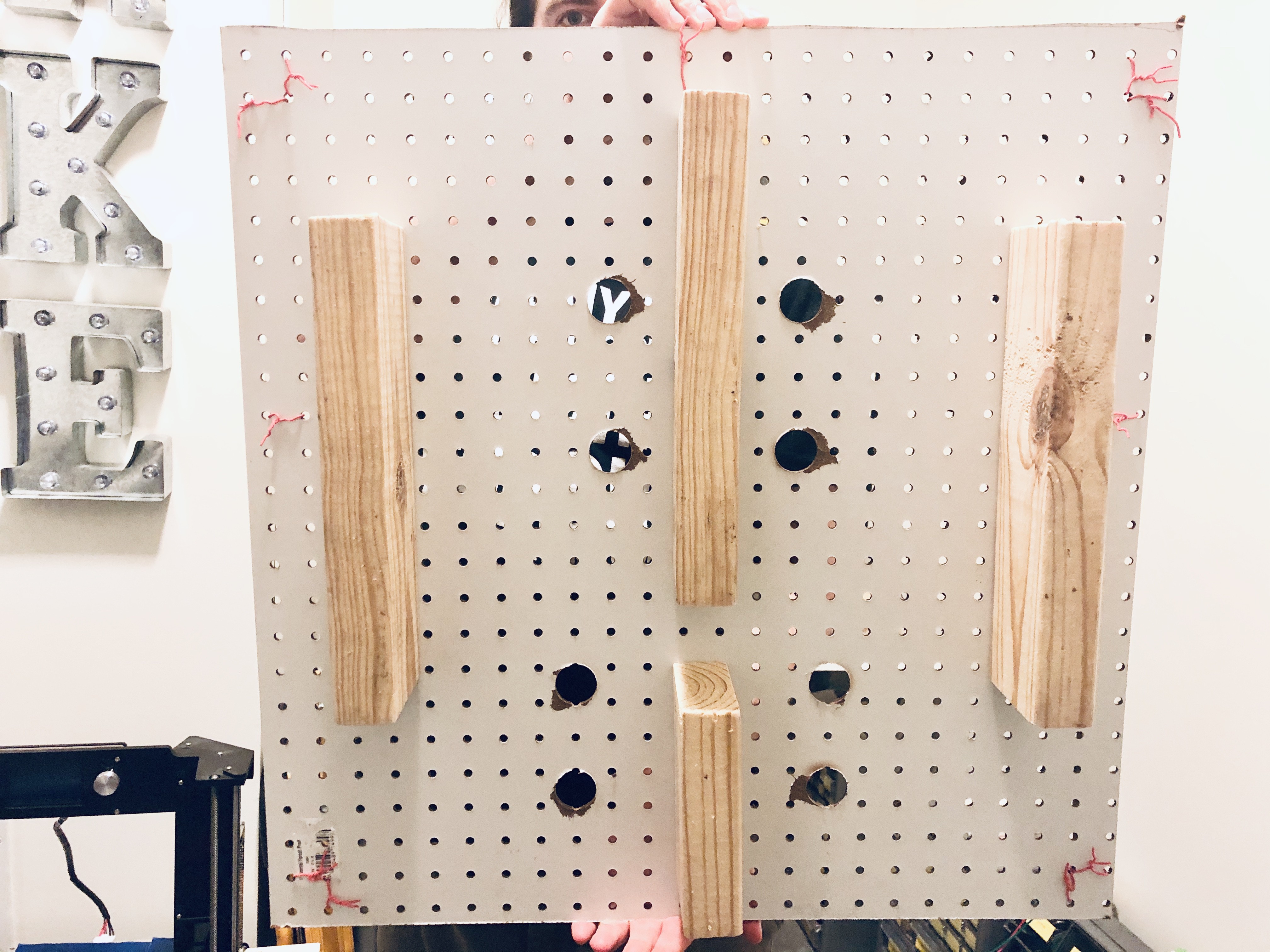
Pictured below are three 2 ' long planks, that were 1.5 " wide and 3.5 " tall.
![]()
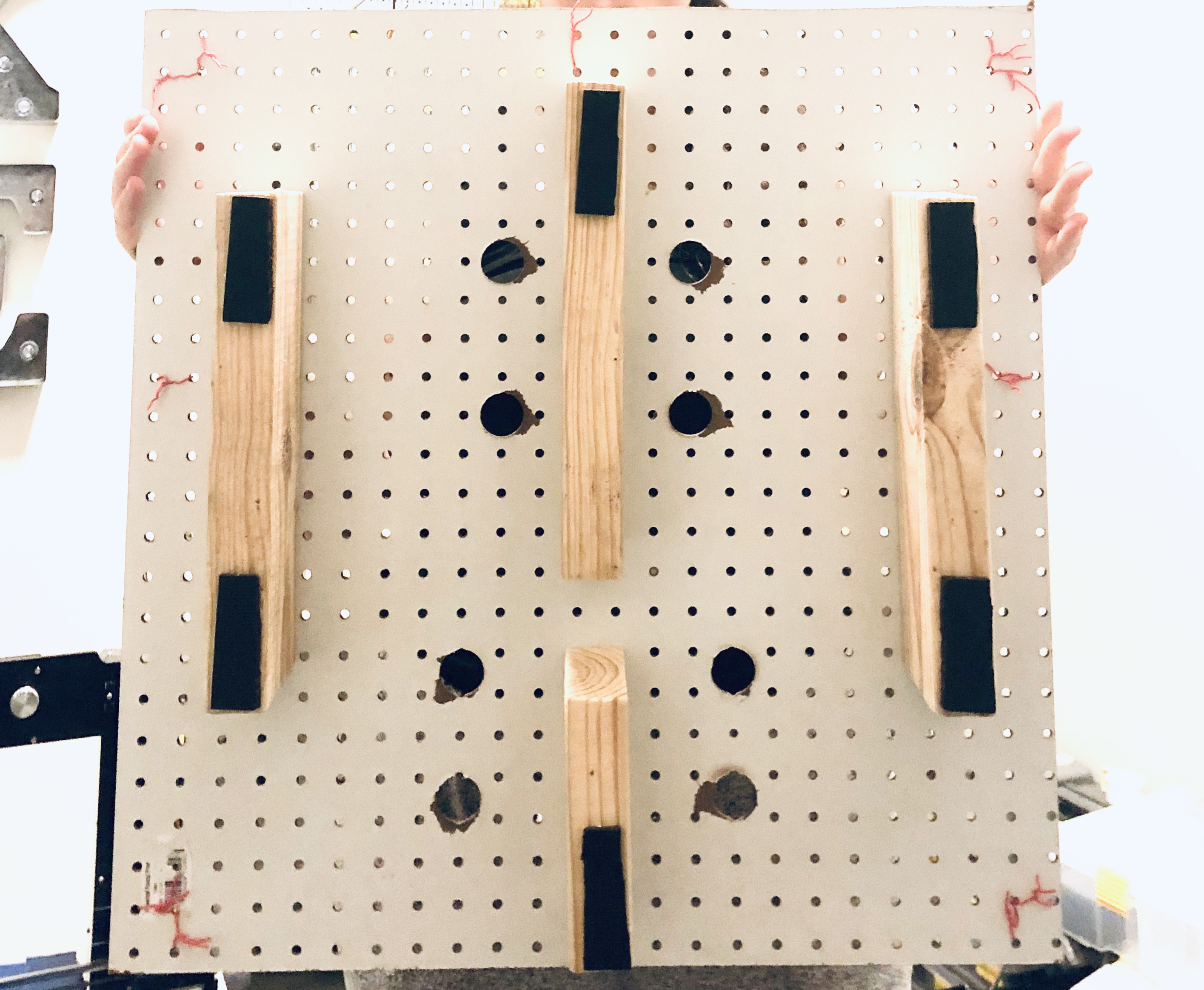
The planks were cut into three 1 ' long planks and one 6 " plank with a handsaw. Below is a picture of the configuration they will be when placed under the board. The middle planks are for making sure there is adequate support when pressure is applied from hitting the arcade buttons. This is so the board doesn't wobble!
![]()
These supporting planks also serve a second use - to prop up the peg board off the ground, so that when we drill holes to mount the arcade buttons, the floor wouldn't be damaged.
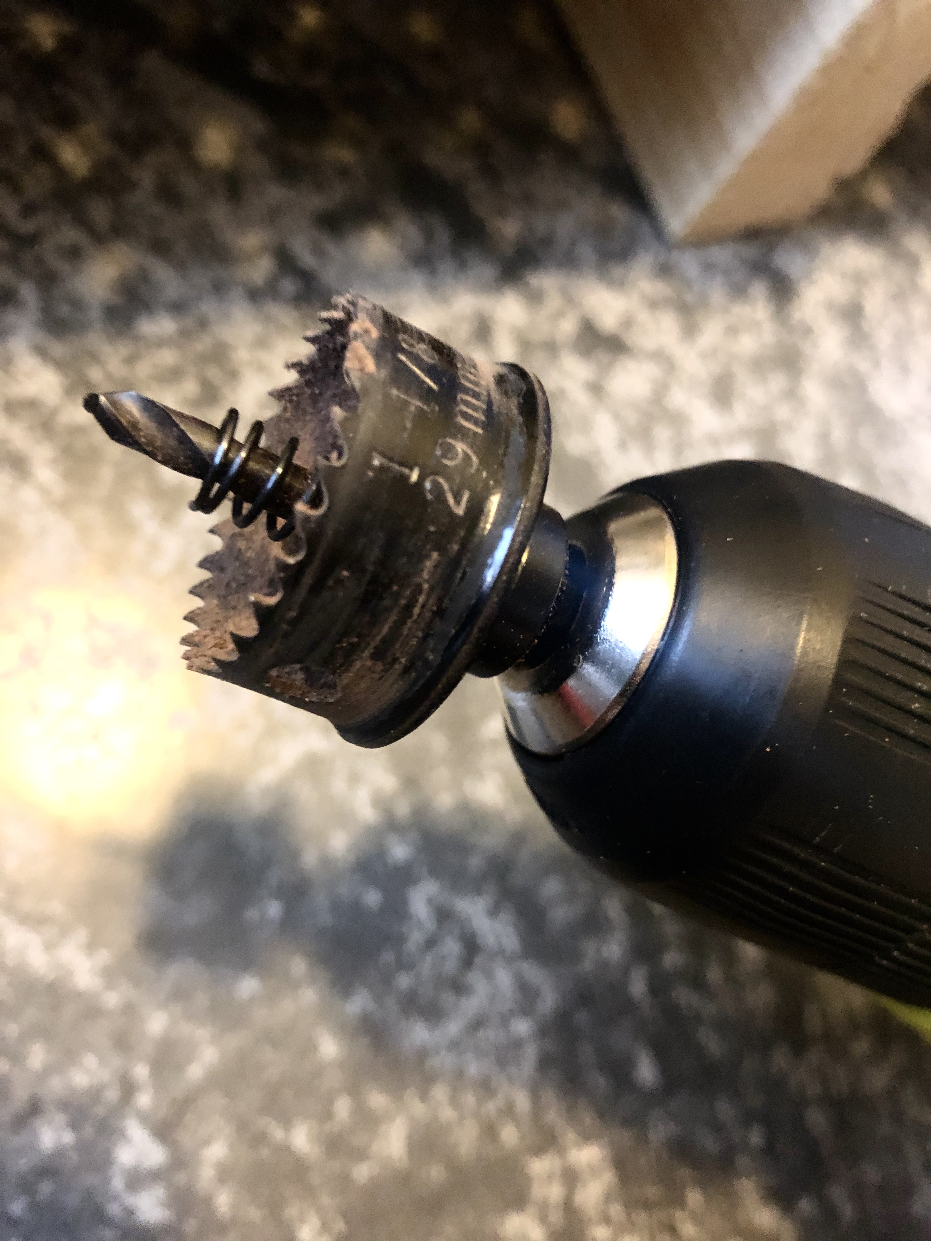
Next step is to drill holes large enough for the arcade buttons into the pegboard using a core drill bit (29mm).
![]()
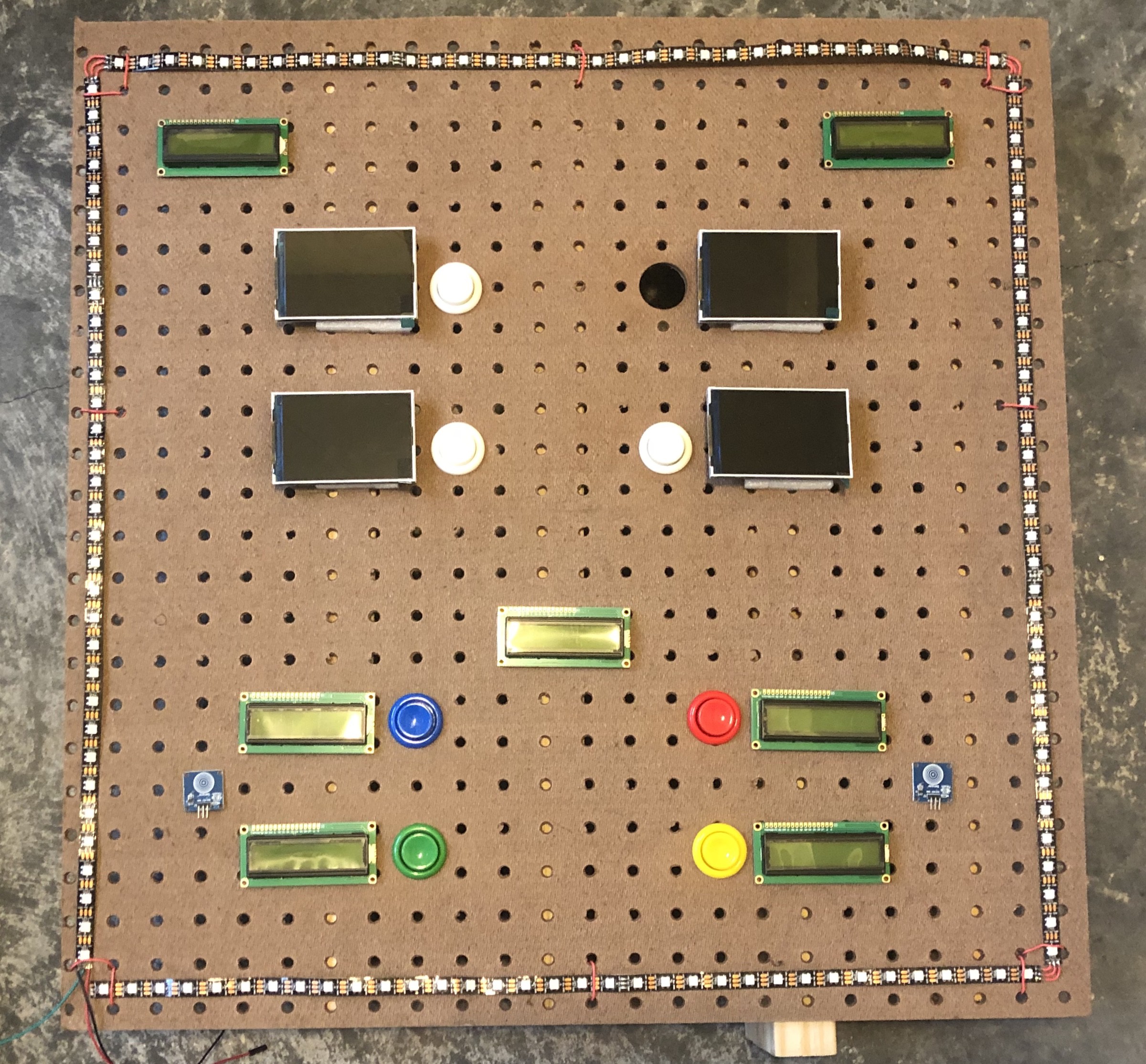
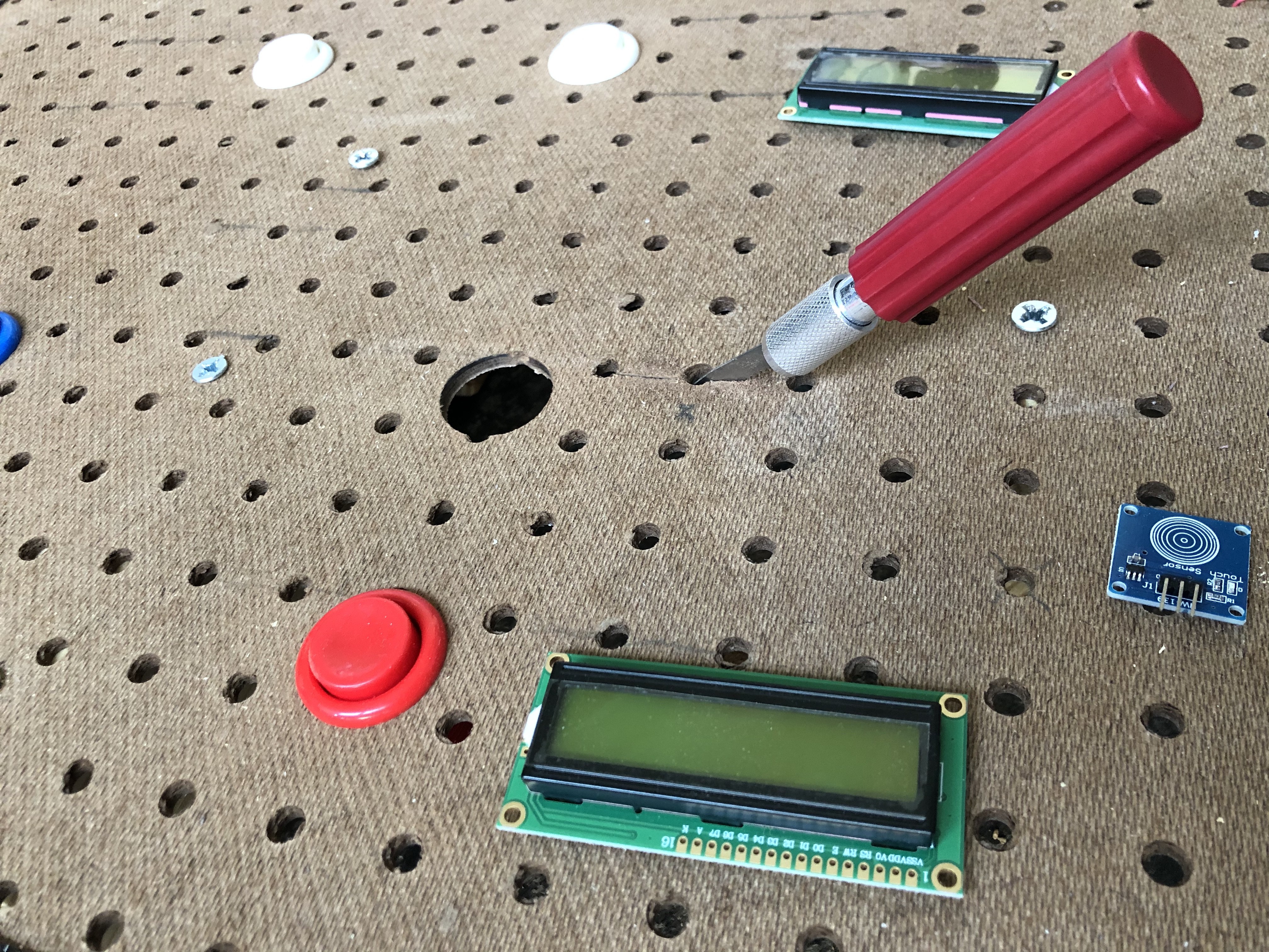
Here is a quick image of what things will look like when the components are mounted:
![]()
After drilling the holes, we next attach the planks to the back of the pegboard.
To do this, we want to pre-drill the board with a smaller bit where all the #8 screws will be drilled into the plank, through the pegboard.
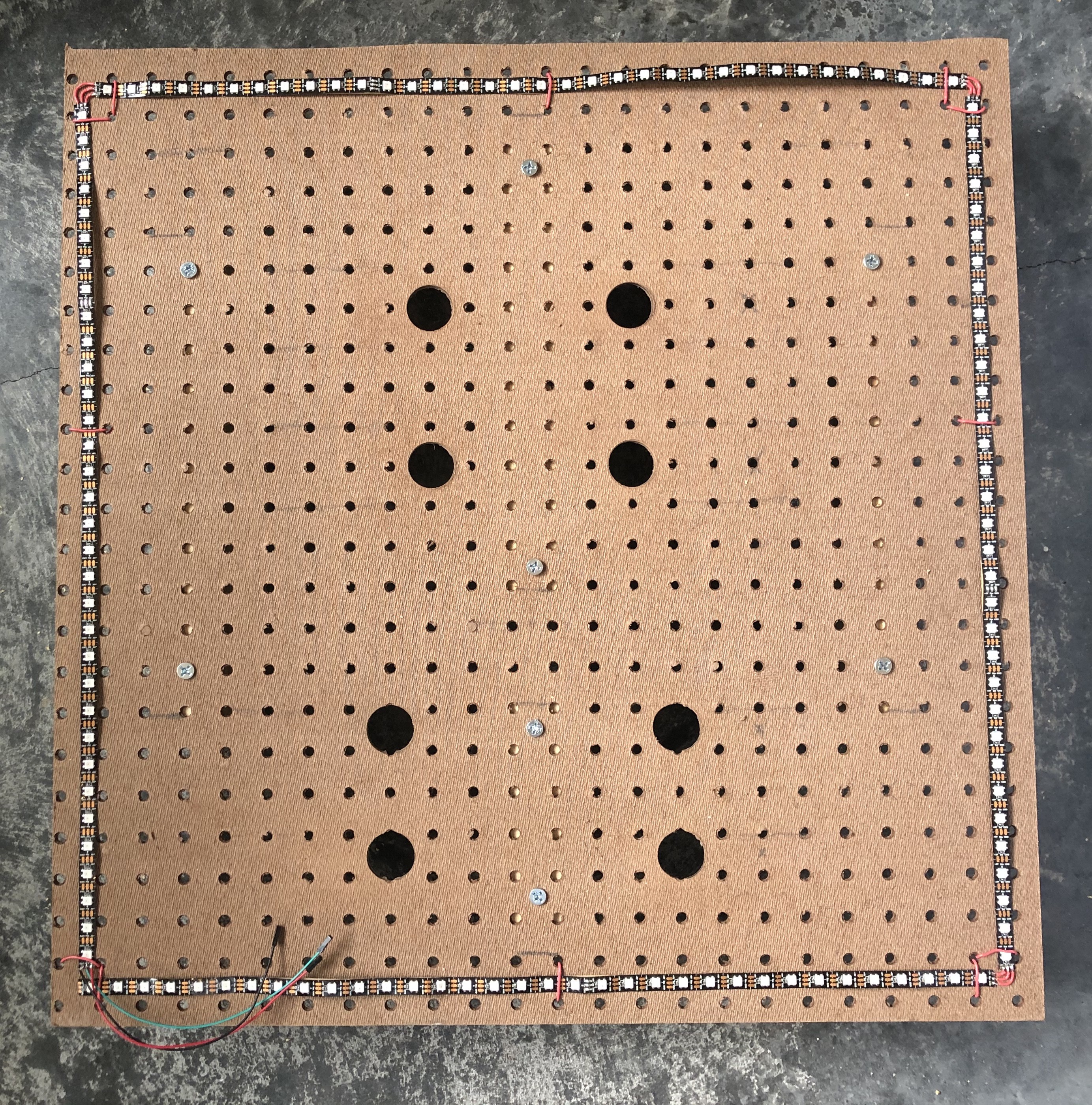
Here is a view from the front and back!
![]()
![]()
If you want to not damage any hardwood floors and make it quieter to set down, you can add little rubber feet like this:
![]()
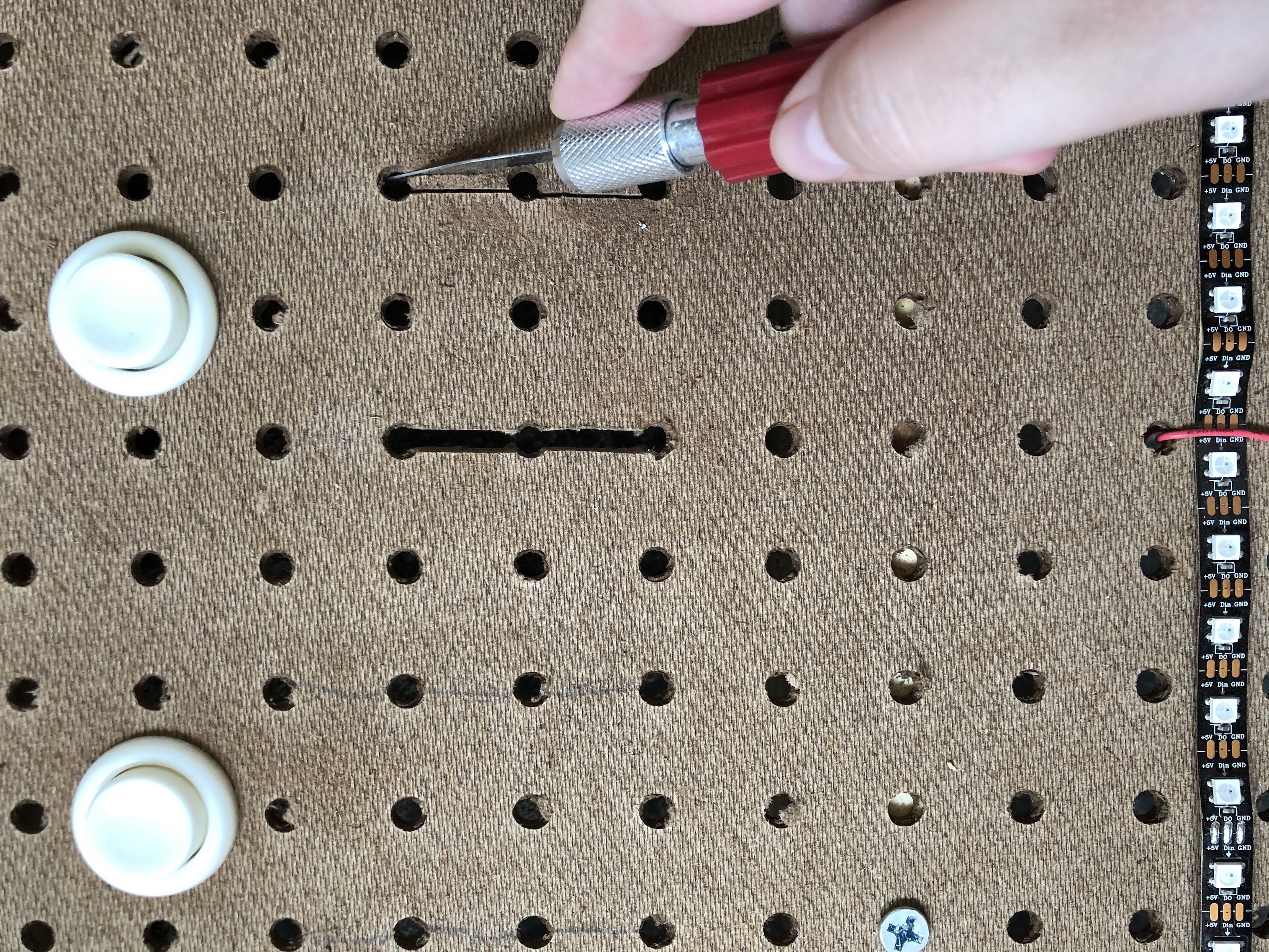
Next step is to cut straight lines connecting some of the dots, so to speak. This is to allow clearance for the wires from the backs of the LCD Displays and TFT LCD Displays. I marked straight lines and cut them using a small hand saw.
![]()
![]()
![]()
Our board is now ready for all the components to be attached. There is now enough clearance for the arcade buttons and wiring of all the other electrical components as well.
-
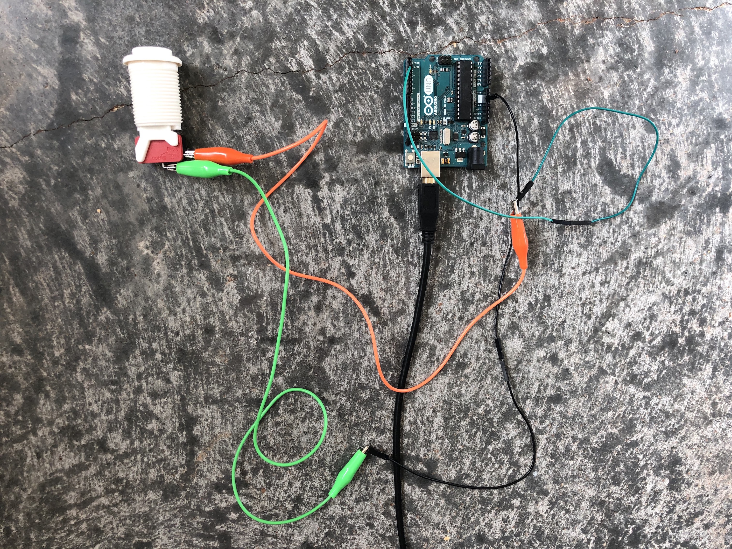
5Arcade Pushbuttons - Setup and Testing
![]()
Following code was modified from the Arduino Button tutorial:
const int buttonPin = 2;
int buttonState = 0;

void setup() {
  Serial.begin(9600);
  pinMode(buttonPin, INPUT_PULLUP);
}

void loop() {
  buttonState = digitalRead(buttonPin);

  if (buttonState == HIGH) {
    Serial.println("Button is high");
  } else {
    Serial.println("Button is low");
  }
}
NOTE: If you don't use the Arduino's internal pullup resistor or an external resistor to ground your circuit when it's in an open state (unpushed), then the output will be unreliable, as it will vary between a high and low state even without being pressed.
-
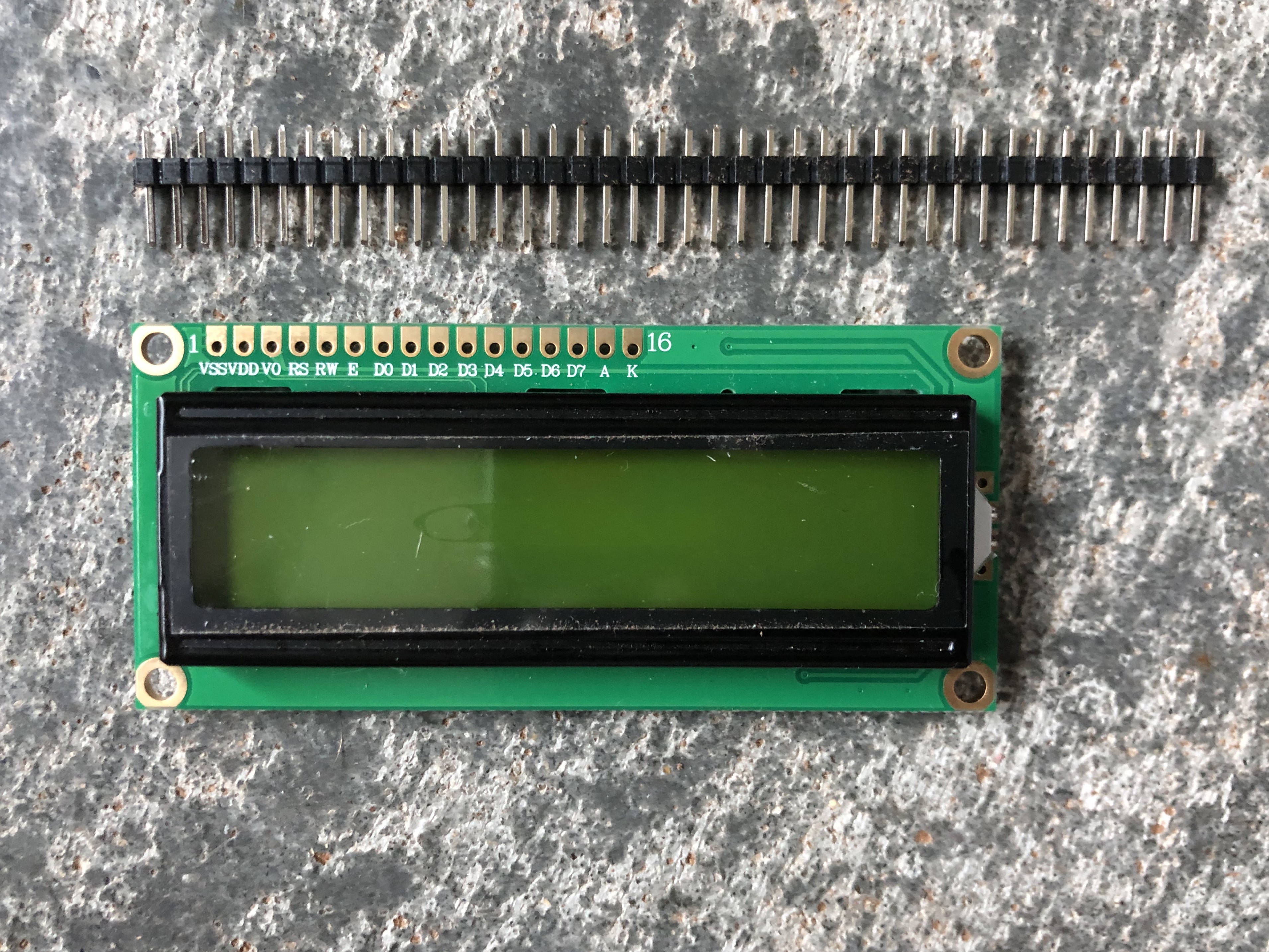
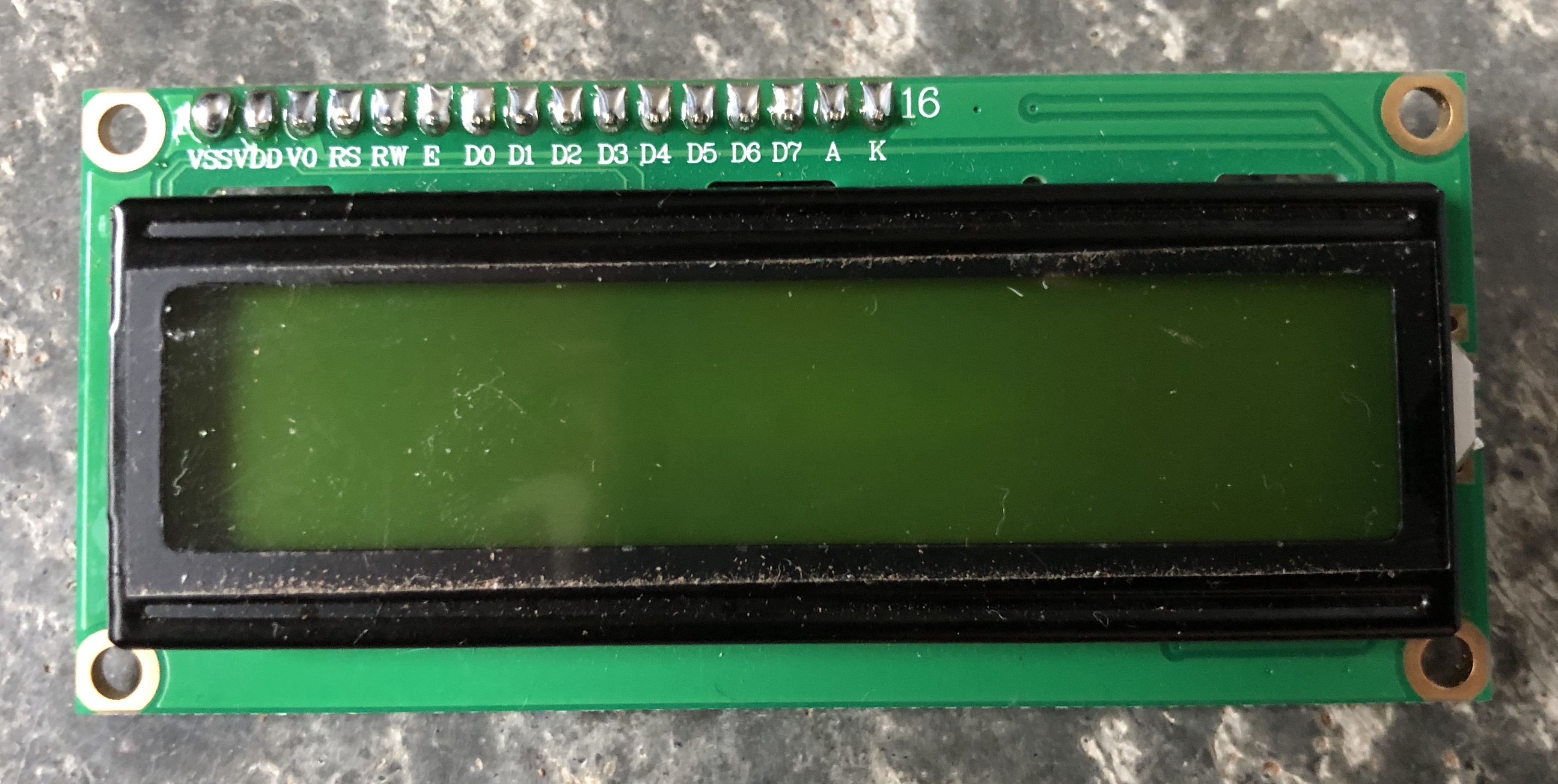
6LCD's - Setup and Testing
![]()
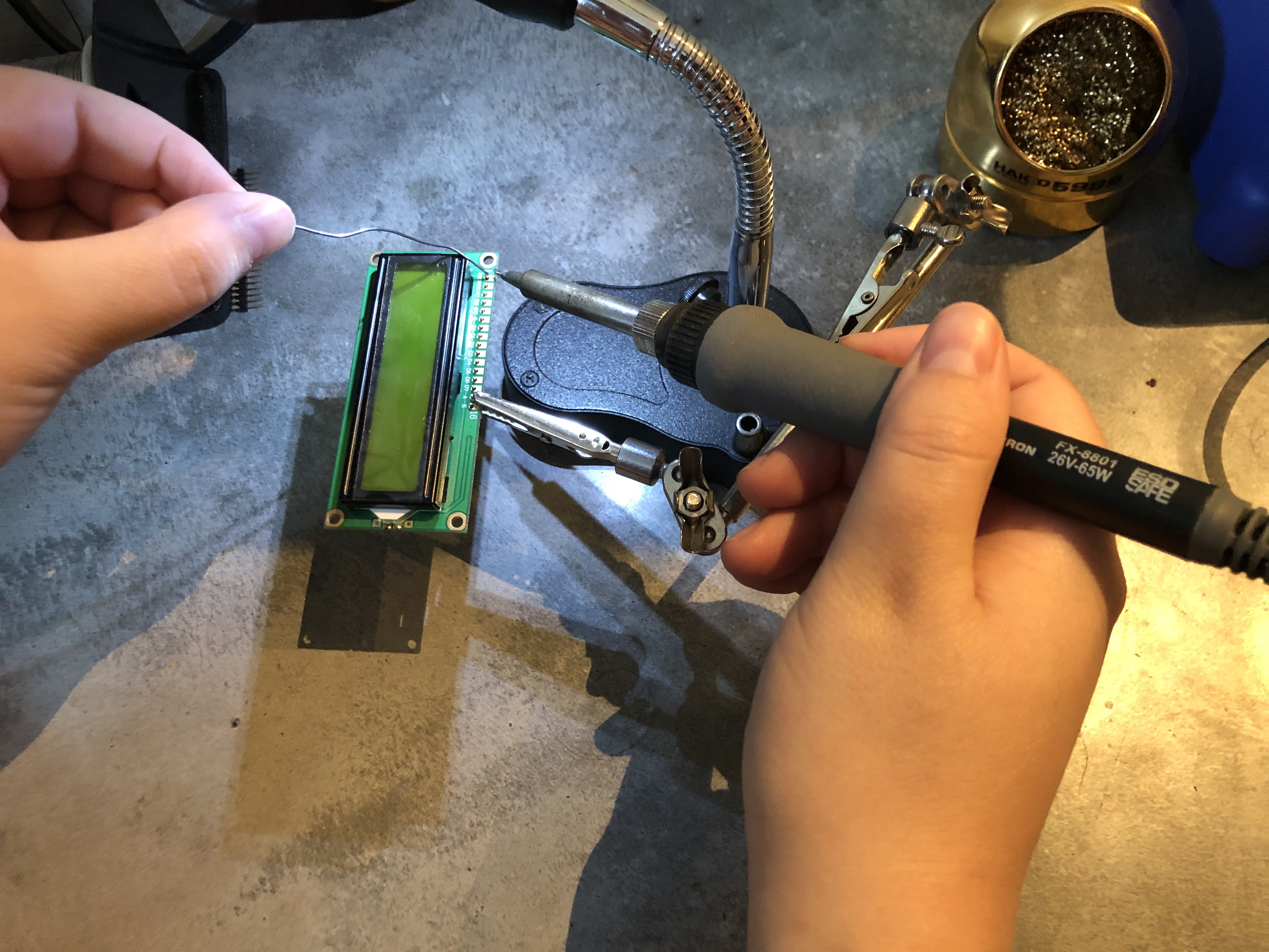
Snap off 16 male header pins and solder them to the LCD.
![]()
The LCD should now look like this
![]()
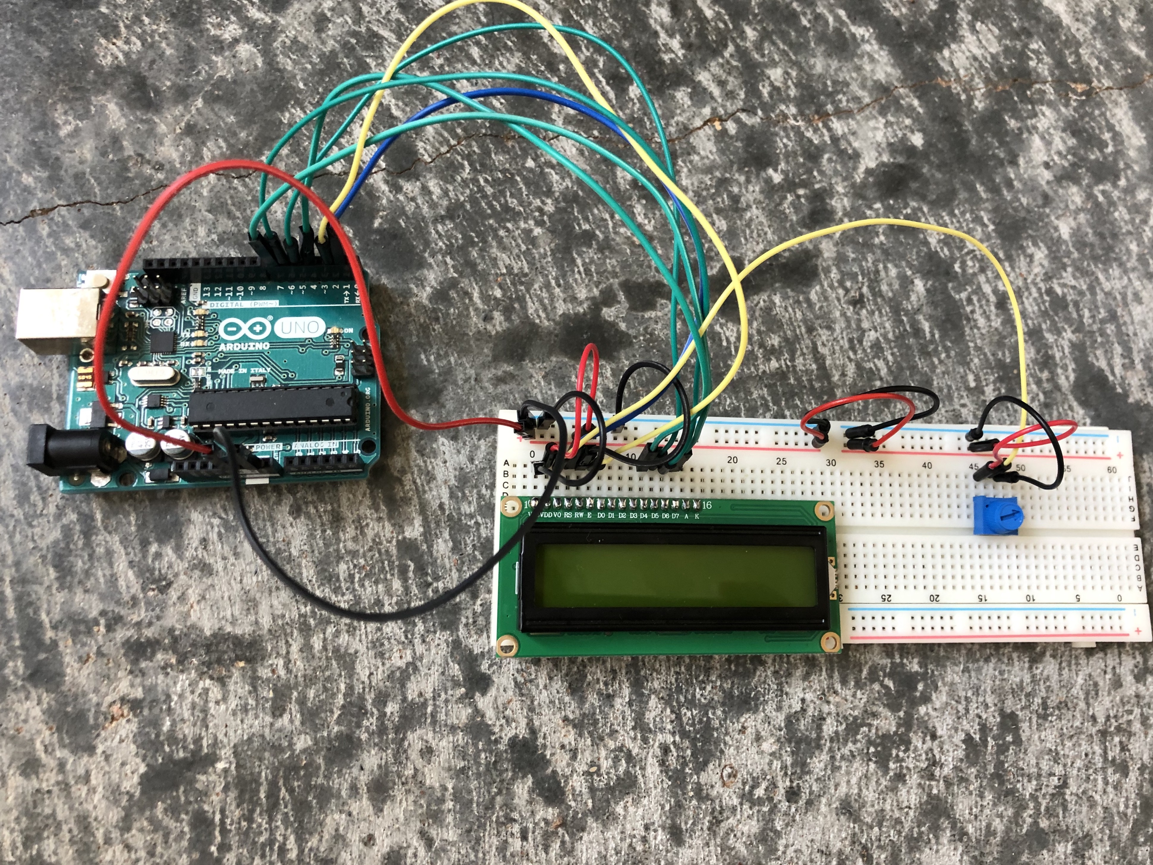
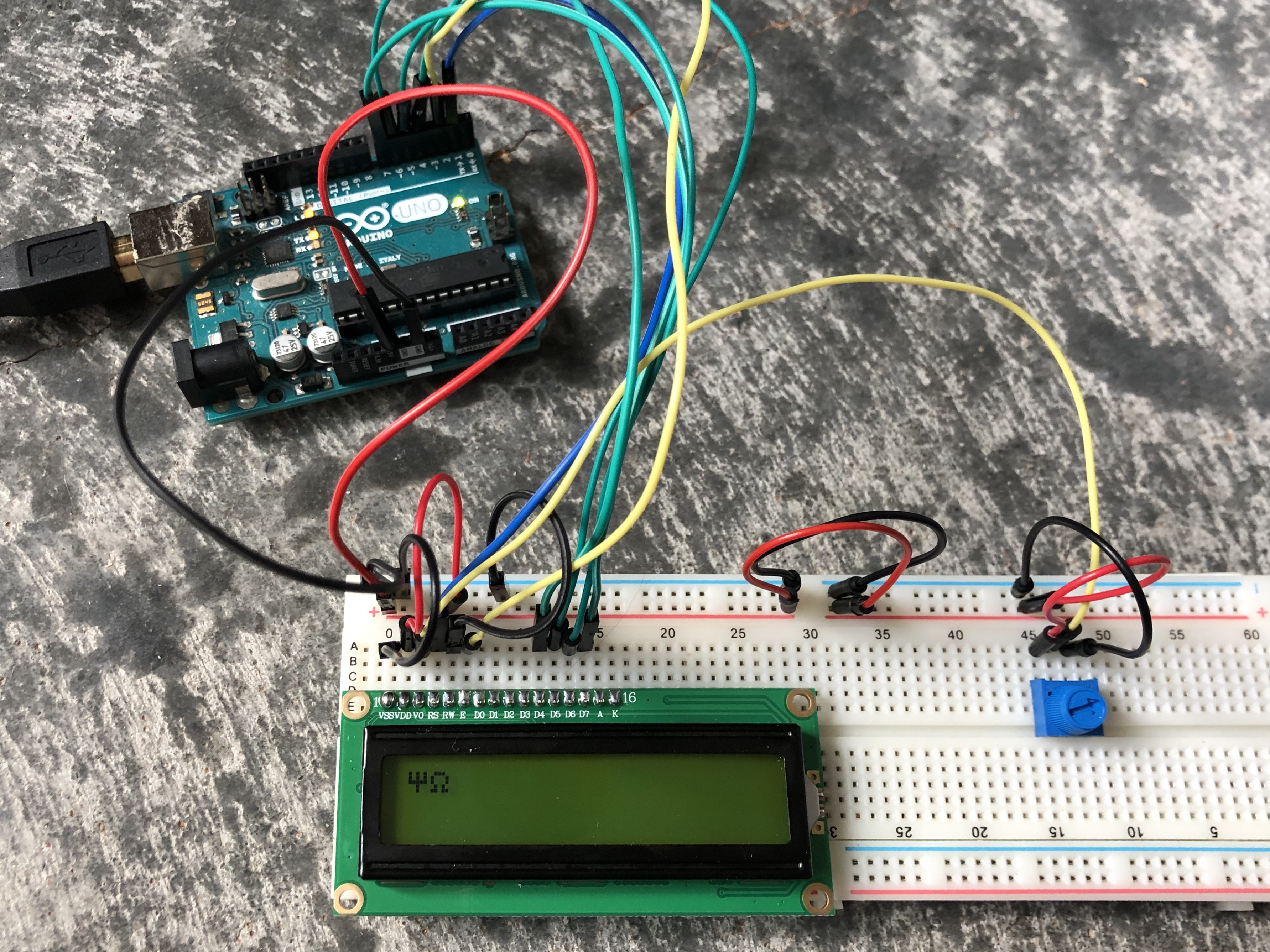
Below is a picture of all the wiring for a single LCD connected to an Arduino UNO with a potentiometer for contrast control.
![]()
Wiring for this circuit was completed by following this tutorial by How To Mechatronics. Code below was modified from its original source from the tutorial.
#include <LiquidCrystal.h> // includes the LiquidCrystal Library

// Creates an LC object.
// Parameters: (rs, enable, d4, d5, d6, d7)
LiquidCrystal lcd(1, 2, 4, 5, 6, 7);

// Initializes the interface to the LCD screen,
// and specifies the dimensions (width and height)
// of the display
void setup() {
 lcd.begin(16,2);
}

void loop() {
 // Prints "CATEGORIES" on the LCD
 lcd.print("CATEGORIES");
 // 3 seconds delay
 delay(3000);
 // Sets the location at which subsequent text
 // written to the LCD will be displayed
 lcd.setCursor(2,1);
 lcd.noBlink();
 lcd.noCursor();
 delay(3000);
 // Clears the LCD screen
 lcd.clear();
}
>>> ADDITIONAL NOTES
The original idea was that six out of seven LCD's will print english characters and the remaining LCD would print Greek characters. The player would hear the Greek word through the speaker and also see the printed word on display until they made their selection.
A little background: there are 26 letters in the English alphabet and 24 letters in the Greek alphabet. Lower case letters in the Greek alphabet can have accent mark on top to indicate an emphasis on that letter. Below is the Greek alphabet for reference:
![]()
For creating your own custom characters for the LCD, there's a pretty cool online resource ( LCD Custom Character Generator) that lets you do that using a GUI and outputs the code changes live, so all you have to do is copy and paste the byte code into your Arduino sketch to add a new custom character.
However, the LCD has a limit for the number of custom characters you can add due to the size of its RAM. Therefore you can only add 8 custom characters. Unfortunately, there are 10 custom characters (Δ, Γ, Θ, Λ, Ξ, Π, Σ, Φ, Ψ, Ω) we would need to complete the Greek alphabet and so we will have to stick to displaying English phonetics of the greek spoken word for now. Perhaps in version 2 of GVR, there will be a complete redesign utilizing less restrictive hardware.
Note: In case the hardware for LCD is updated at some point to include more ram (which would allow more custom characters), I created all the greek characters in lowercase and uppercase. Here is the link for the LCD Arduino code for lowercase Greek characters and uppercase Greek characters.
Here's what the uppercase characters look like on the LCD:
![]()
![]()
-
7TFT LCD Displays - Setup and Testing
For wiring the 3.5inch TFT LCD to Arduino UNO, please refer to the interface section in the WIKI.
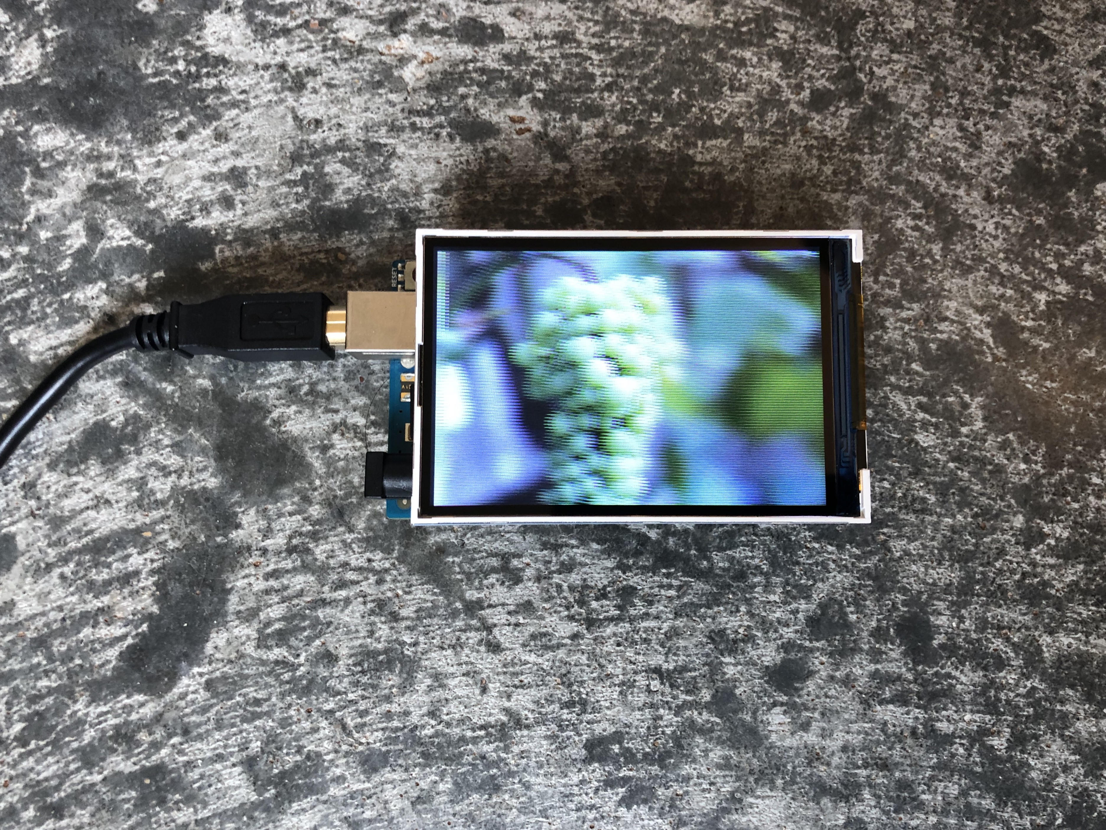
The resolution of these TFT LCD's is 480 x 320 (W x H). That is 480 pixels wide and 320 pixels tall if in landscape orientation or 320 pixels wide and 480 pixels tall if in portrait orientation. Here is what a bmp file looks like when first loaded onto the TFT with no code edits made in the example code below:
![]()
Since the default orientation for these displays is portrait mode, you need to call the .setRotation() function and pass in 1 to indicate you want landscape mode. This is mentioned in Adafruit's post on rotating the display.
All images should be sized down to 480 x 320 dimensions and also saved as .bmp files with 24-bit depth (most common setting) onto a micro SD card. NOTE: Gimp was used to convert the image into a bmp file format, using the advanced option to make sure the image exported as 24-bit depth. Before converting with Gimp, I tried to use an app from the Apple store to bulk convert png file format to bmp and the images were showing up like this on the TFT display:
![]()
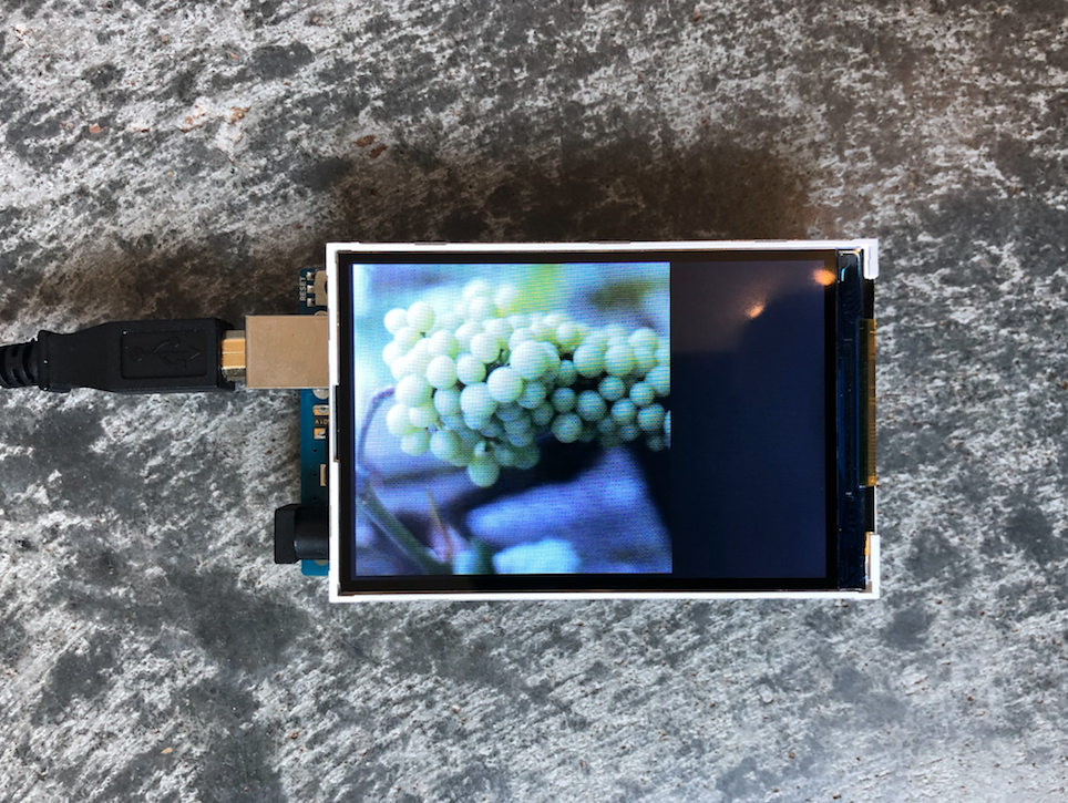
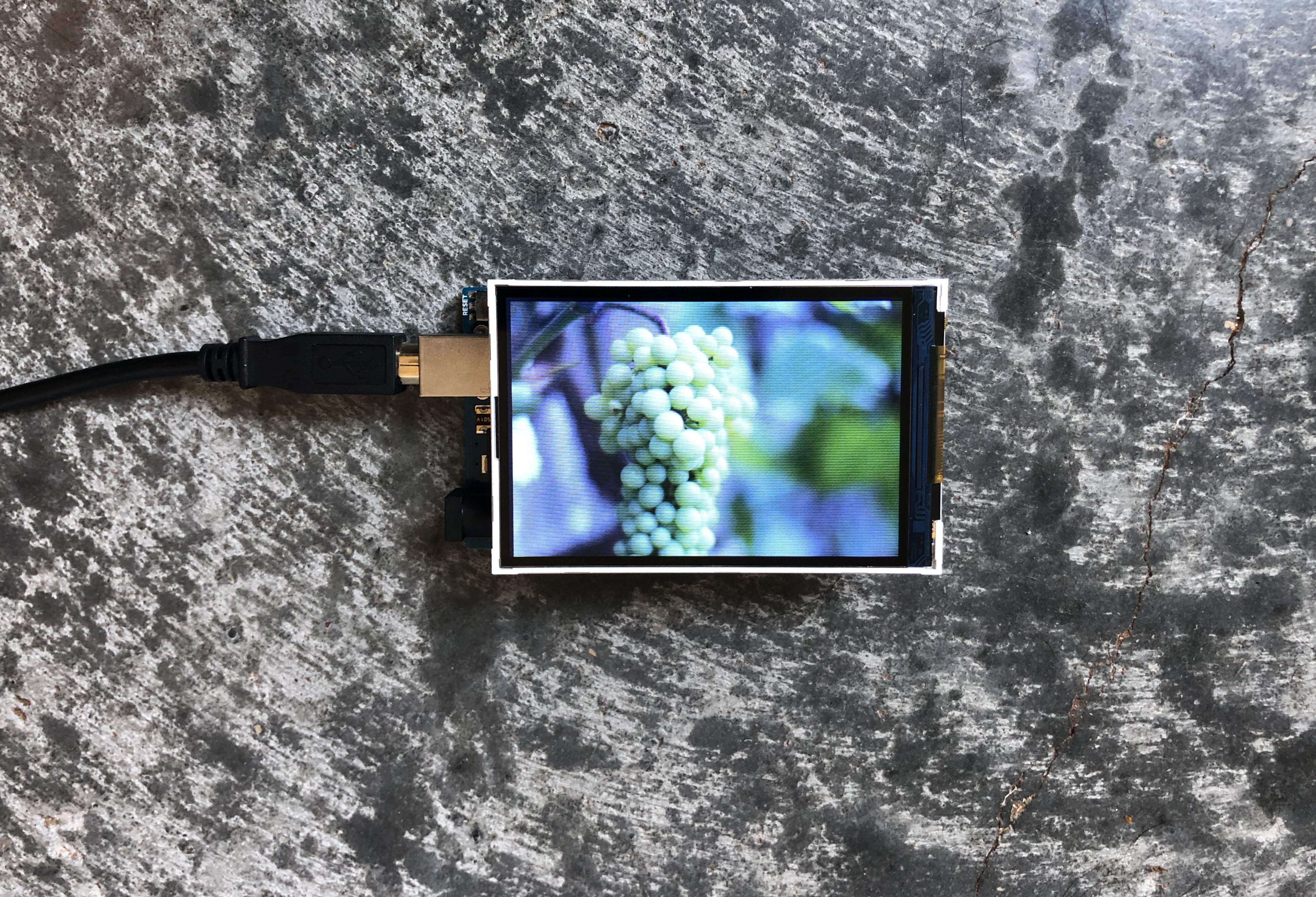
Here is what the image looked like after converting with GIMP:
![]()
Code below modified from Arduino example library. You must first install the 'MCUFRIEND_kbv' library through Arduino by going to Sketch > Include Library > Manage Libraries. Find the library and click install. Then to find this code example, go to File > Examples > MCUFRIEND_kbv > showBMP_kbv_Uno.
// MCUFRIEND UNO shields have microSD on pins 10, 11, 12, 13
// The official <SD.h> library only works on the hardware SPI pins
// e.g. 11, 12, 13 on a Uno  (or STM32 Nucleo)
//
// copy all your BMP files to the root directory on the microSD with your PC
// (or another directory)

#include <SPI.h>            // f.k. for Arduino-1.5.2
//#define USE_SDFAT
#include <SD.h>             // Use the official SD library on hardware pins

#include <Adafruit_GFX.h>   // Hardware-specific library
#include <MCUFRIEND_kbv.h>
MCUFRIEND_kbv tft;

#if defined(ESP32)
#define SD_CS     5
#else
#define SD_CS     10
#endif
#define NAMEMATCH ""        // "" matches any name
//#define NAMEMATCH "tiger"   // *tiger*.bmp
#define PALETTEDEPTH   0     // do not support Palette modes
//#define PALETTEDEPTH   8     // support 256-colour Palette

char namebuf[32] = "/";   //BMP files in root directory
//char namebuf[32] = "/bitmaps/";  //BMP directory e.g. files in /bitmaps/*.bmp

File root;
int pathlen;

void setup()
{
    uint16_t ID;
    Serial.begin(9600);
    Serial.print("Show BMP files on TFT with ID:0x");
    ID = tft.readID();
    Serial.println(ID, HEX);
    if (ID == 0x0D3D3) ID = 0x9481;
    tft.begin(ID);

    // for changing the image orientation to landscape
    tft.setRotation(1);
    Serial.println("Width");
    Serial.println(tft.width());
    Serial.println("Height");
    Serial.println(tft.height());
    tft.fillScreen(0x001F);
    tft.setTextColor(0xFFFF, 0x0000);
    bool good = SD.begin(SD_CS);
    if (!good) {
        Serial.print(F("cannot start SD"));
        while (1);
    }
    root = SD.open(namebuf);
    pathlen = strlen(namebuf);
}

void loop()
{
    char *nm = namebuf + pathlen;
    File f = root.openNextFile();
    uint8_t ret;
    uint32_t start;
    if (f != NULL) {
#ifdef USE_SDFAT
        f.getName(nm, 32 - pathlen);
#else
        strcpy(nm, (char *)f.name());
#endif
        f.close();
        strlwr(nm);
        if (strstr(nm, ".bmp") != NULL && strstr(nm, NAMEMATCH) != NULL) {
            Serial.print(namebuf);
            Serial.print(F(" - "));
            tft.fillScreen(0);
            start = millis();
            ret = showBMP(namebuf, 5, 5);
            switch (ret) {
                case 0:
                    Serial.print(millis() - start);
                    Serial.println(F("ms"));
                    delay(5000);
                    break;
                case 1:
                    Serial.println(F("bad position"));
                    break;
                case 2:
                    Serial.println(F("bad BMP ID"));
                    break;
                case 3:
                    Serial.println(F("wrong number of planes"));
                    break;
                case 4:
                    Serial.println(F("unsupported BMP format"));
                    break;
                case 5:
                    Serial.println(F("unsupported palette"));
                    break;
                default:
                    Serial.println(F("unknown"));
                    break;
            }
        }
    }
    else root.rewindDirectory();
}

#define BMPIMAGEOFFSET 54

#define BUFFPIXEL      20

uint16_t read16(File& f) {
    uint16_t result;         // read little-endian
    f.read((uint8_t*)&result, sizeof(result));
    return result;
}

uint32_t read32(File& f) {
    uint32_t result;
    f.read((uint8_t*)&result, sizeof(result));
    return result;
}

uint8_t showBMP(char *nm, int x, int y)
{
    File bmpFile;
    int bmpWidth, bmpHeight;    // W+H in pixels
    uint8_t bmpDepth;           // Bit depth (currently must be 24, 16, 8, 4, 1)
    uint32_t bmpImageoffset;    // Start of image data in file
    uint32_t rowSize;           // Not always = bmpWidth; may have padding
    uint8_t sdbuffer[3 * BUFFPIXEL];    // pixel in buffer (R+G+B per pixel)
    uint16_t lcdbuffer[(1 << PALETTEDEPTH) + BUFFPIXEL], *palette = NULL;
    uint8_t bitmask, bitshift;
    boolean flip = true;        // BMP is stored bottom-to-top
    int w, h, row, col, lcdbufsiz = (1 << PALETTEDEPTH) + BUFFPIXEL, buffidx;
    uint32_t pos;               // seek position
    boolean is565 = false;      //

    uint16_t bmpID;
    uint16_t n;                 // blocks read
    uint8_t ret;

    if ((x >= tft.width()) || (y >= tft.height()))
        return 1;               // off screen

    bmpFile = SD.open(nm);      // Parse BMP header
    bmpID = read16(bmpFile);    // BMP signature
    (void) read32(bmpFile);     // Read & ignore file size
    (void) read32(bmpFile);     // Read & ignore creator bytes
    bmpImageoffset = read32(bmpFile);       // Start of image data
    (void) read32(bmpFile);     // Read & ignore DIB header size
    bmpWidth = read32(bmpFile);
    bmpHeight = read32(bmpFile);
    n = read16(bmpFile);        // # planes -- must be '1'
    bmpDepth = read16(bmpFile); // bits per pixel
    pos = read32(bmpFile);      // format
    if (bmpID != 0x4D42) ret = 2; // bad ID
    else if (n != 1) ret = 3;   // too many planes
    else if (pos != 0 && pos != 3) ret = 4; // format: 0 = uncompressed, 3 = 565
    else if (bmpDepth < 16 && bmpDepth > PALETTEDEPTH) ret = 5; // palette
    else {
        bool first = true;
        is565 = (pos == 3);               // ?already in 16-bit format
        // BMP rows are padded (if needed) to 4-byte boundary
        rowSize = (bmpWidth * bmpDepth / 8 + 3) & ~3;
        if (bmpHeight < 0) {              // If negative, image is in top-down order.
            bmpHeight = -bmpHeight;
            flip = false;
        }

        w = bmpWidth;
        h = bmpHeight;
        if ((x + w) >= tft.width())       // Crop area to be loaded
            w = tft.width() - x;
        if ((y + h) >= tft.height())      //
            h = tft.height() - y;

        if (bmpDepth <= PALETTEDEPTH) {   // these modes have separate palette
            bmpFile.seek(BMPIMAGEOFFSET); //palette is always @ 54
            bitmask = 0xFF;
            if (bmpDepth < 8)
                bitmask >>= bmpDepth;
            bitshift = 8 - bmpDepth;
            n = 1 << bmpDepth;
            lcdbufsiz -= n;
            palette = lcdbuffer + lcdbufsiz;
            for (col = 0; col < n; col++) {
                pos = read32(bmpFile);    //map palette to 5-6-5
                palette[col] = ((pos & 0x0000F8) >> 3) | ((pos & 0x00FC00) >> 5) | ((pos & 0xF80000) >> 8);
            }
        }

        // Set TFT address window to clipped image bounds
        tft.setAddrWindow(x, y, x + w - 1, y + h - 1);
        for (row = 0; row < h; row++) { // For each scanline...
            // Seek to start of scan line.  It might seem labor-
            // intensive to be doing this on every line, but this
            // method covers a lot of gritty details like cropping
            // and scanline padding.  Also, the seek only takes
            // place if the file position actually needs to change
            // (avoids a lot of cluster math in SD library).
            uint8_t r, g, b, *sdptr;
            int lcdidx, lcdleft;
            if (flip)   // Bitmap is stored bottom-to-top order (normal BMP)
                pos = bmpImageoffset + (bmpHeight - 1 - row) * rowSize;
            else        // Bitmap is stored top-to-bottom
                pos = bmpImageoffset + row * rowSize;
            if (bmpFile.position() != pos) { // Need seek?
                bmpFile.seek(pos);
                buffidx = sizeof(sdbuffer); // Force buffer reload
            }

            for (col = 0; col < w; ) {  //pixels in row
                lcdleft = w - col;
                if (lcdleft > lcdbufsiz) lcdleft = lcdbufsiz;
                for (lcdidx = 0; lcdidx < lcdleft; lcdidx++) { // buffer at a time
                    uint16_t color;
                    // Time to read more pixel data?
                    if (buffidx >= sizeof(sdbuffer)) { // Indeed
                        bmpFile.read(sdbuffer, sizeof(sdbuffer));
                        buffidx = 0; // Set index to beginning
                        r = 0;
                    }
                    switch (bmpDepth) {          // Convert pixel from BMP to TFT format
                        case 24:
                            b = sdbuffer[buffidx++];
                            g = sdbuffer[buffidx++];
                            r = sdbuffer[buffidx++];
                            color = tft.color565(r, g, b);
                            break;
                        case 16:
                            b = sdbuffer[buffidx++];
                            r = sdbuffer[buffidx++];
                            if (is565)
                                color = (r << 8) | (b);
                            else
                                color = (r << 9) | ((b & 0xE0) << 1) | (b & 0x1F);
                            break;
                        case 1:
                        case 4:
                        case 8:
                            if (r == 0)
                                b = sdbuffer[buffidx++], r = 8;
                            color = palette[(b >> bitshift) & bitmask];
                            r -= bmpDepth;
                            b <<= bmpDepth;
                            break;
                    }
                    lcdbuffer[lcdidx] = color;

                }
                tft.pushColors(lcdbuffer, lcdidx, first);
                first = false;
                col += lcdidx;
            }           // end cols
        }               // end rows
        tft.setAddrWindow(0, 0, tft.width() - 1, tft.height() - 1); //restore full screen
        ret = 0;        // good render
    }
    bmpFile.close();
    return (ret);
}
Note in the demo video, the image loads slowly with this code example:
-
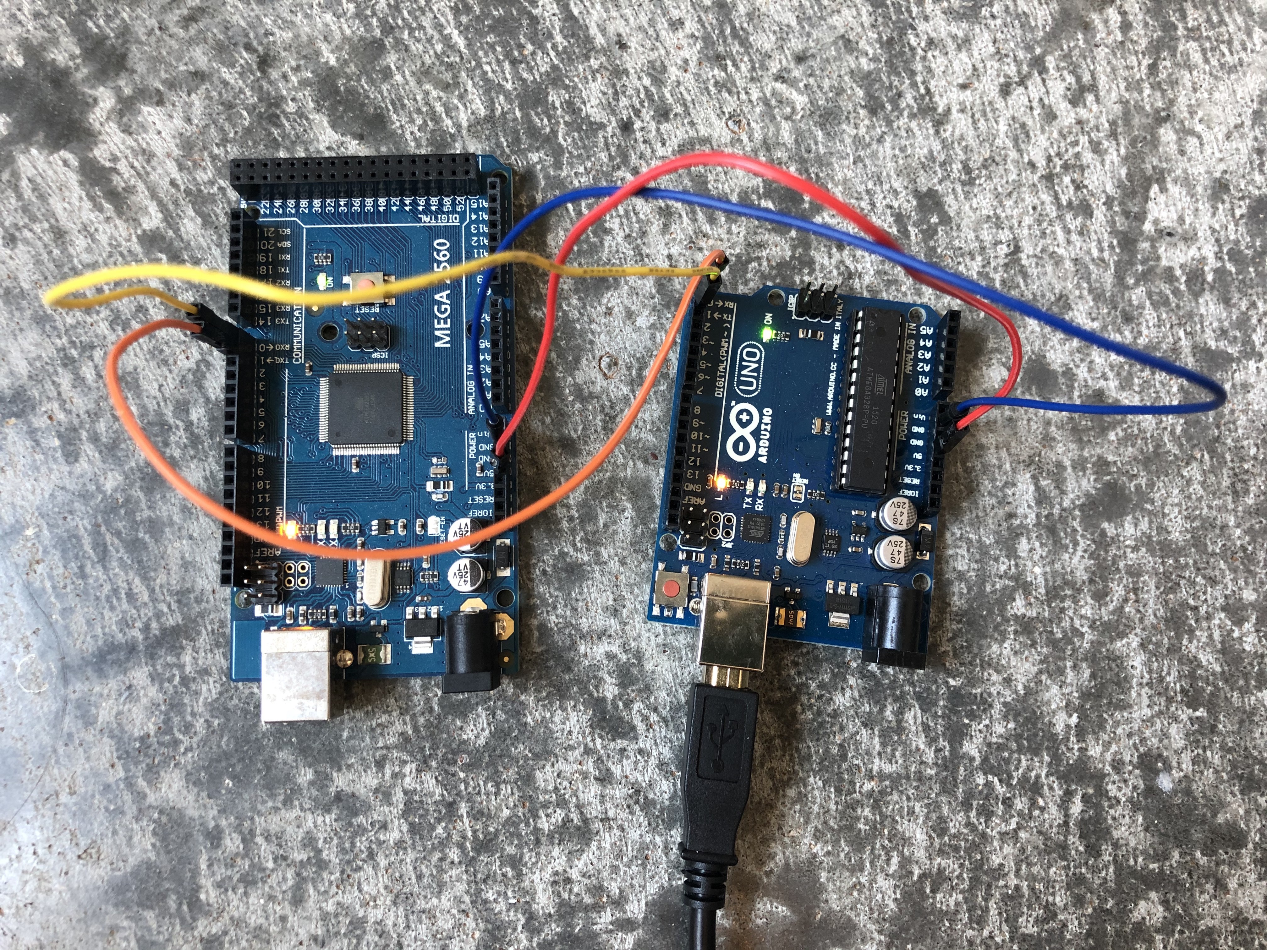
8Serial Communication between Arduino Mega and Arduino UNO
![]()
Code below for communication between two Arduinos is modified from this forum post: https://forum.arduino.cc/index.php?topic=288234.0 for the receiver code and this tutorial: https://iot-guider.com/arduino/serial-communication-between-two-arduino-boards/ for the sender code.
Sender code:
char mystr[7] = "<Hello>"; //String data

void setup() {
  // Begin the Serial at 9600 Baud
  Serial.begin(9600);
}

void loop() {
  Serial.write(mystr,7); //Write the serial data
  delay(1000);
}
Receiver code:
const byte numChars = 32;
char receivedChars[numChars];

boolean newData = false;

void setup() {
    Serial.begin(9600);
    Serial.println("<Arduino is ready>");
}

void loop() {
    recvWithStartEndMarkers();
    showNewData();
}

void recvWithStartEndMarkers() {
    static boolean recvInProgress = false;
    static byte ndx = 0;
    char startMarker = '<';
    char endMarker = '>';
    char rc;

 // if (Serial.available() > 0) {
    while (Serial.available() > 0 && newData == false) {
        rc = Serial.read();
//        Serial.println(rc);

        if (recvInProgress == true) {
            if (rc != endMarker) {
                receivedChars[ndx] = rc;
                ndx++;
                if (ndx >= numChars) {
                    ndx = numChars - 1;
                }
            }
            else {
                receivedChars[ndx] = '\0'; // terminate the string
                recvInProgress = false;
                ndx = 0;
                newData = true;
            }
        }

        else if (rc == startMarker) {
            recvInProgress = true;
        }
    }
}

void showNewData() {
    if (newData == true) {
        Serial.print("This just in ... ");
        Serial.println(receivedChars);
        newData = false;
    }
}
Video demo of communication with Arduino MEGA being the sender and Arduino UNO being the receiver:
-
9Tying it all together
Since each TFT LCD needs its own Arduino UNO, here we see the wiring for how to send messages from an Arduino MEGA (sender) to each UNO (receiver). This is for sending a command as to which picture will display on each screen.
![]()
Here is a diagram for the LCD power flow:
![]()
Testing the four screens displaying a startup image at the same time:
Here is a video showing the latest progress for this project:
TLDR: Due to some unanticipated pitfalls surrounding the limitations of the Arduino memory capabilities, coupled with difficulties mounting the screens to the game board (the issue being that the power and ground wires were too long when they were spaced apart during the mounting onto the board and given the small diameter of the wires, the current was not reaching the TFT screens fast enough to display the images), I have decided to show where I left off for this version and move onto version 2.
All code files can be found on the GitHub project link.
Greek Vocabulary Reviewer
Greek language vocabulary reviewer via an interactive panel game with arcade pushbuttons, LCD screens, LEDs and more.


Discussions
Become a Hackaday.io Member
Create an account to leave a comment. Already have an account? Log In.