Close
0%
0%

V20-MBC: a V20 (8088 + 8080) CPU homebrew computer

An easy to build homemade single board computer with a V20HL aka uPD70108H (8088 + 8080) or 80C88 CPU. CP/M-80, CP/M-86 and MSDOS supported.

Similar projects worth following
The V20-MBC is an easy to build V20HL (full static CMOS version) or 80C88 CPU SBC (Single Board Computer). It follows the same "concept" of the Z80-MBC2 (https://hackaday.io/project/159973), with an SD as "disk emulator" and up to 1024KB RAM.

It has an optional on board 16x GPIO expander, and uses common cheap add-on modules for the SD and the RTC options.

It has an "Arduino heart" using an Atmega32A as EEPROM and "universal" I/O emulator (so a "legacy" EPROM programmer is not needed) programmed with Arduino IDE.

It is compatible with the uTerm (https://hackaday.io/project/165325) and uCom (https://hackaday.io/project/165709) boards.

* * PREFACE * *

Luckily I have enough electronic stuff "to survive" these days, so I decided to start the design of a new "retro" board, this time using a V20HL CPU. Of course my way...


* * THE PROTOTYPE * *

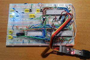
In the first phase of the design I've used a prototype on a breadboard to check the basic "concepts".

To make things easier I've used as "companion" MCU a STM32F030R8 on a custom board (ARMando) I previously made and that it is directly pluggable on breadboards, and with onboard microSD card and USB-serial adapter.:
To make the firmware for the STM32F030R8 I've used Arduino IDE with the core made by ST. In this way the "porting" to the Atmega32 used in the final board would have been simpler.
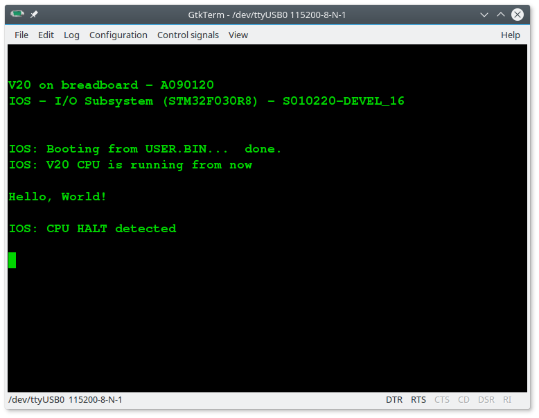
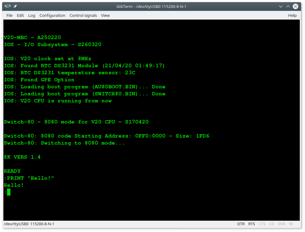
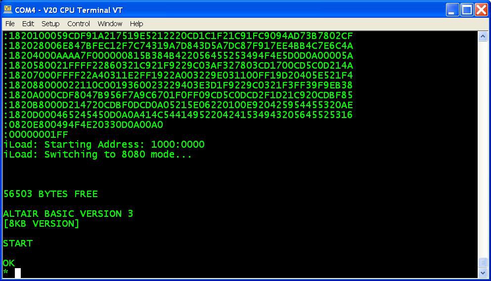
Here some screenshots of some tests using the 8080 mode to run the Altair Basic and the IMSAI Basic:


* * HARDWARE OVERVIEW * *

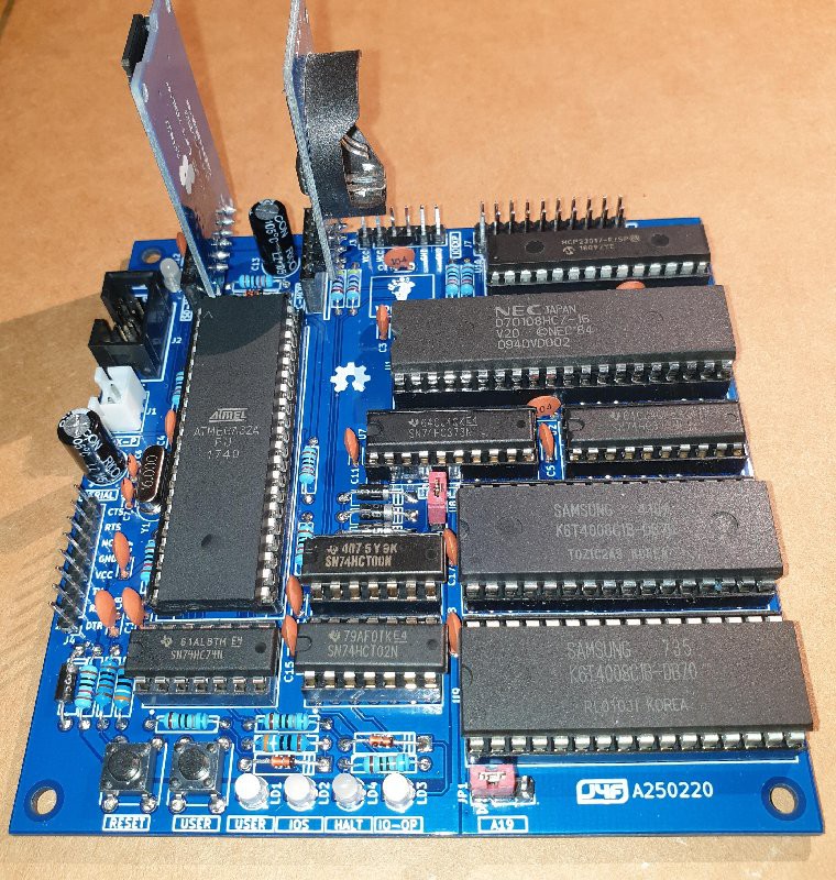
Here the V20-MBC hardware main specs:

- V20HL full static CMOS CPU (uPD70108H)

- can be used an 80C88 (CMOS version) too;

- RAM can be configured as 128/512/1024KB;

- optional RTC and microSD modules (the same used in the Z80-MBC2);

- optional 16x GPIO port;

- I2C expansion port;

- serial port;

- User led and key:

- ISP connector (for the Atmega32);

- clock can be configured at 4/8MHz (by software).

The CPU is used in "minimum mode" to limit the BOM.
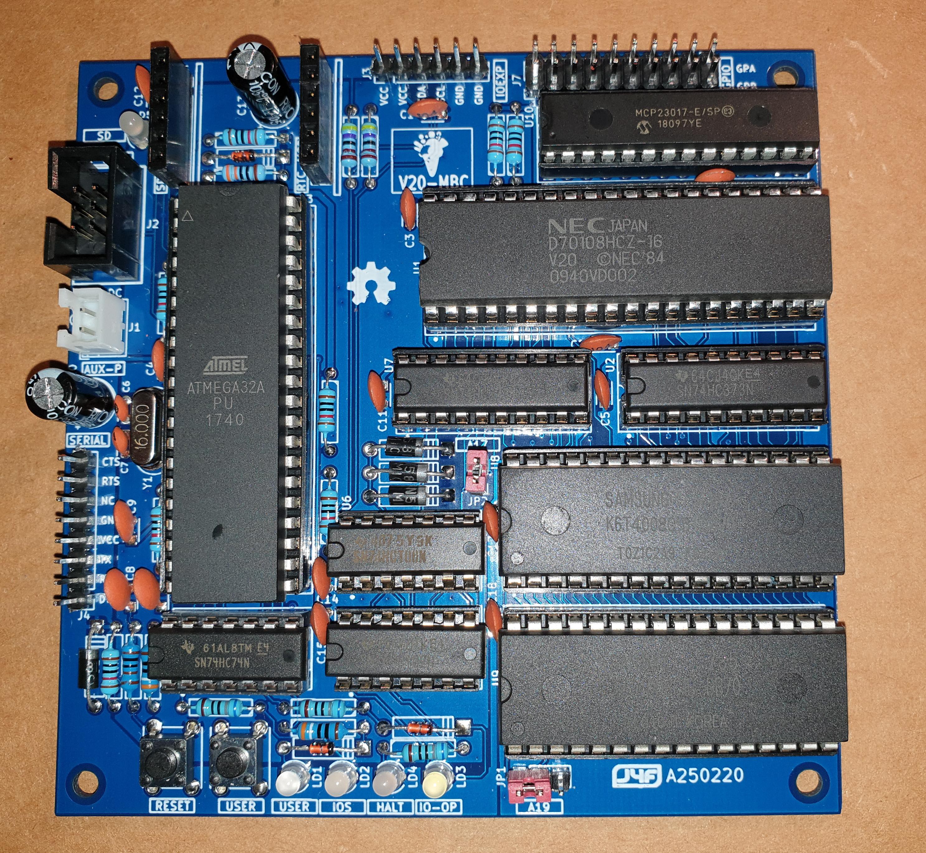
The layout allows to "plug in" a uTerm or a uCom board as in the Z80-MBC2 (vertically or horizontally) using the same 3D printed brackets (the following screenshot could change due to IOS updates).

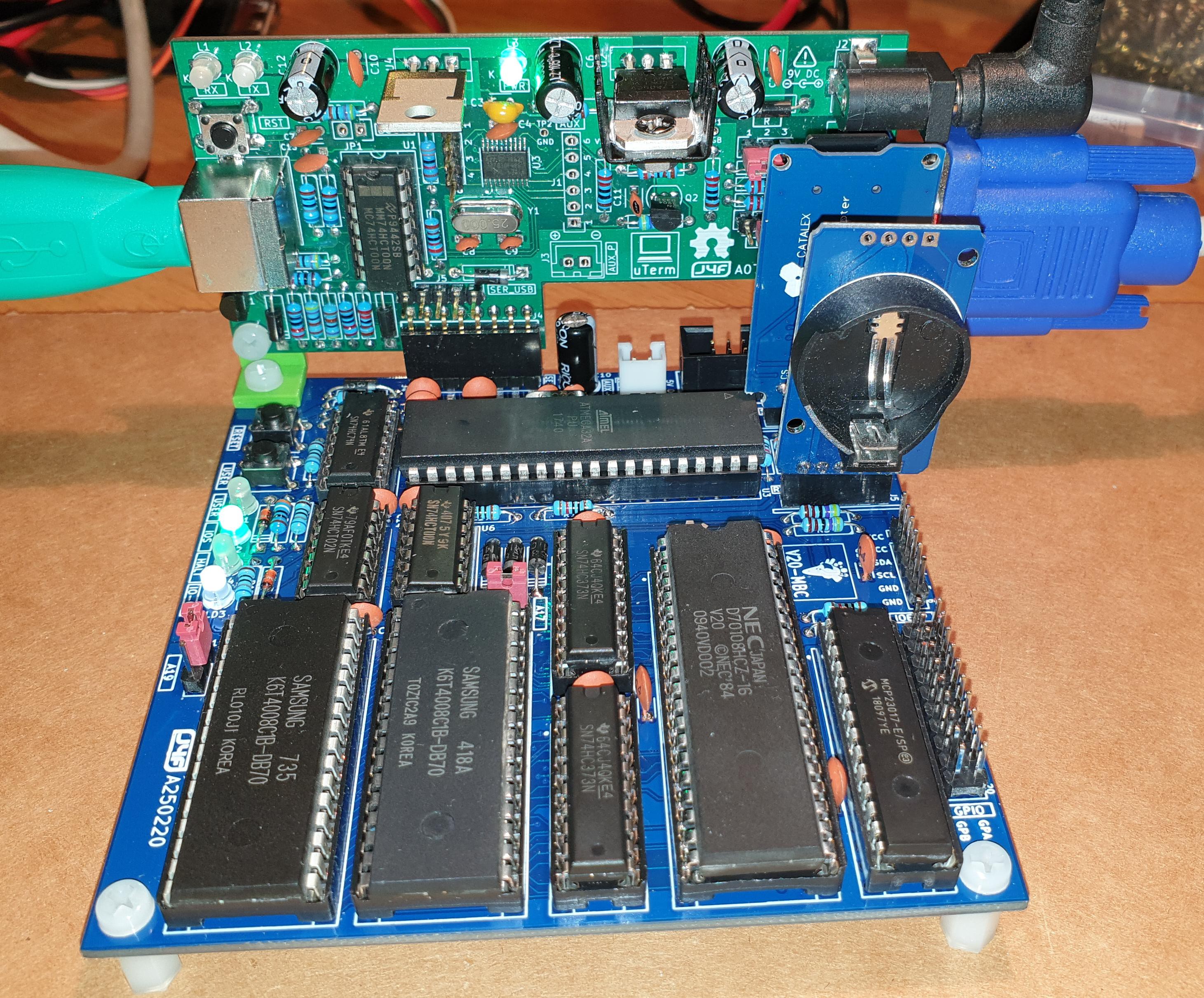
The following images show a V20-MBC attached to a uTerm board to form an "autonomous" unit with a PS/2 keyboard and a VGA monitor (mounted vertically and horizontally):
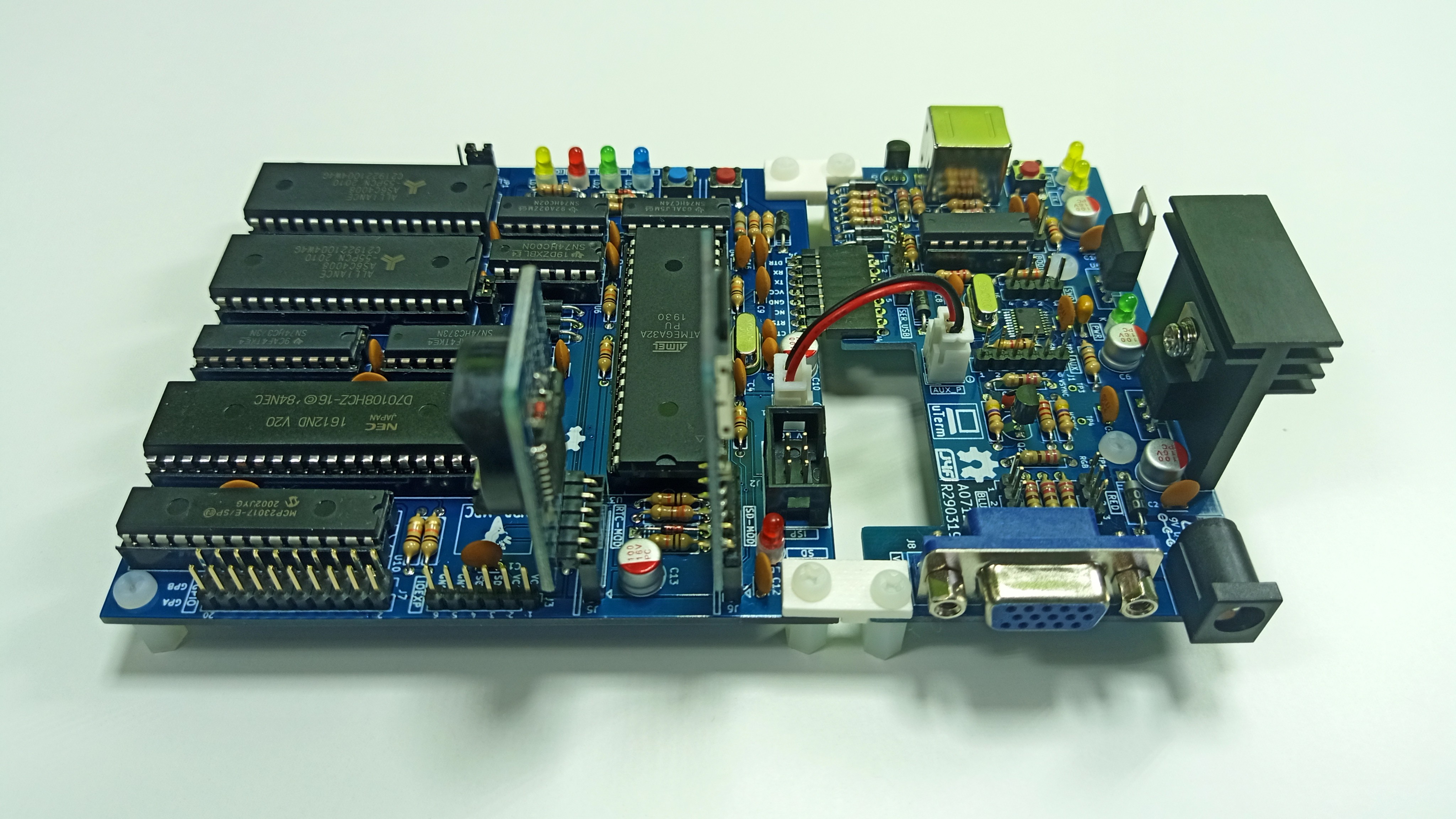

Because it is a "two flavors" board (8088/8080), I've used a two flavors ice cream as logo... ☺

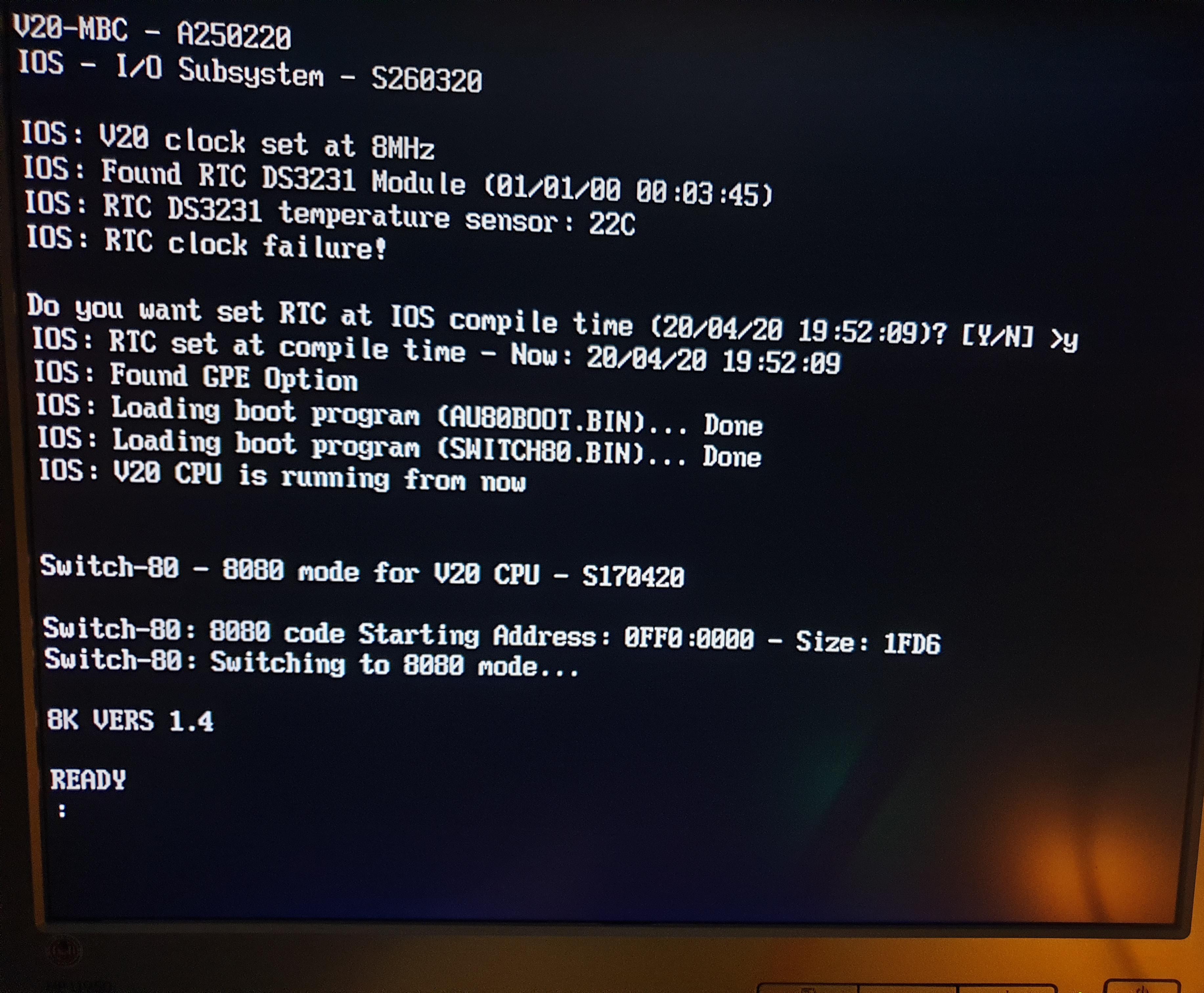
(the following screenshot could change due to IOS updates)
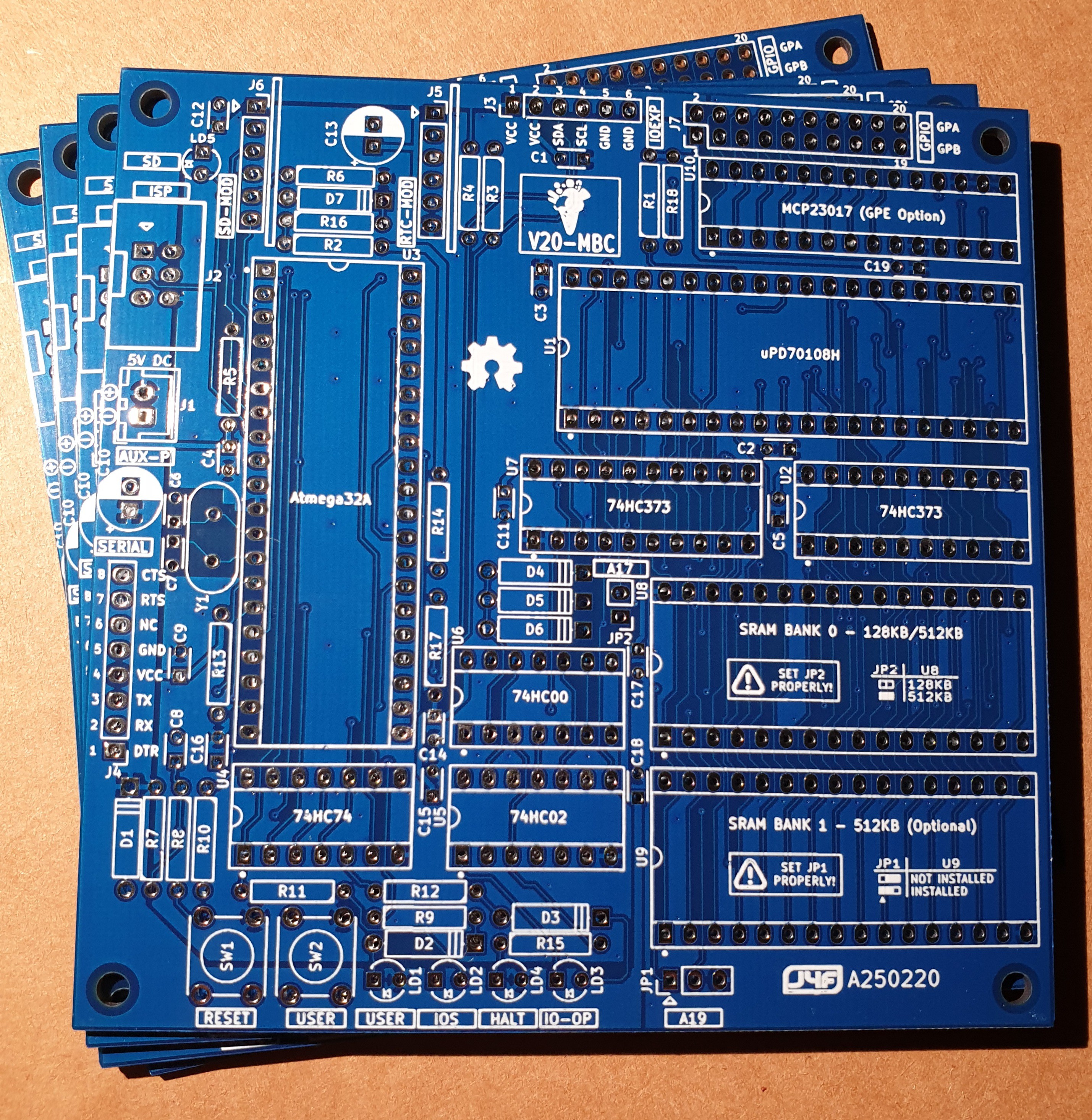

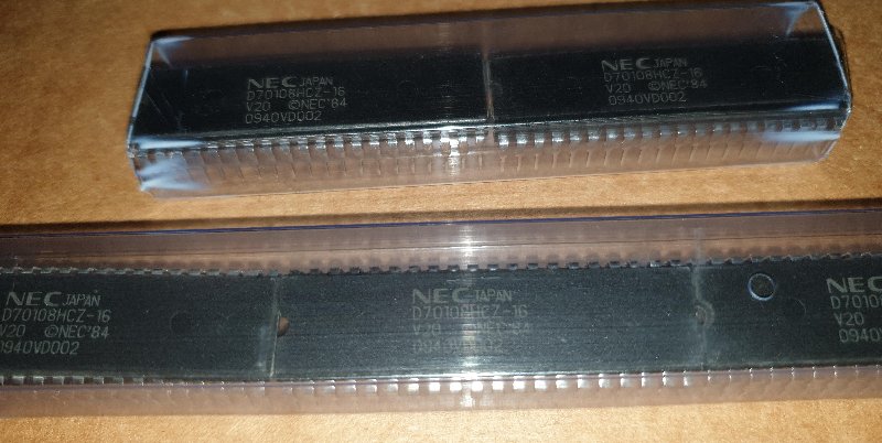
Please remember that a CMOS full static CPU is required here, so the only V20 CPU that can be used is the V20HL (uPD7108H, see the "H" at the end of the part code that makes the difference...).

Only this CMOS full static version allows to use a clock rate from DC and, under some conditions, guaranties that the logic levels are compatible with the Atmega32A ones (the Atmega logic input levels are not TTL compliant)

Another aspect of the V20-MBC is that the well known 8284 clock oscillator chip (normally used to generate the 8088/8086 clock with the required 33% duty cycle) is not used here. Reading  the V20HL datasheet you can see that the -12 and -16 speed grades have a symmetrical clock requirement, and the -10 speed grade clock requirement can be met using a little lower clock with a 50% duty cycle (not greater than about 9MHz, so using a maximum 8MHz clock there is a good margin).
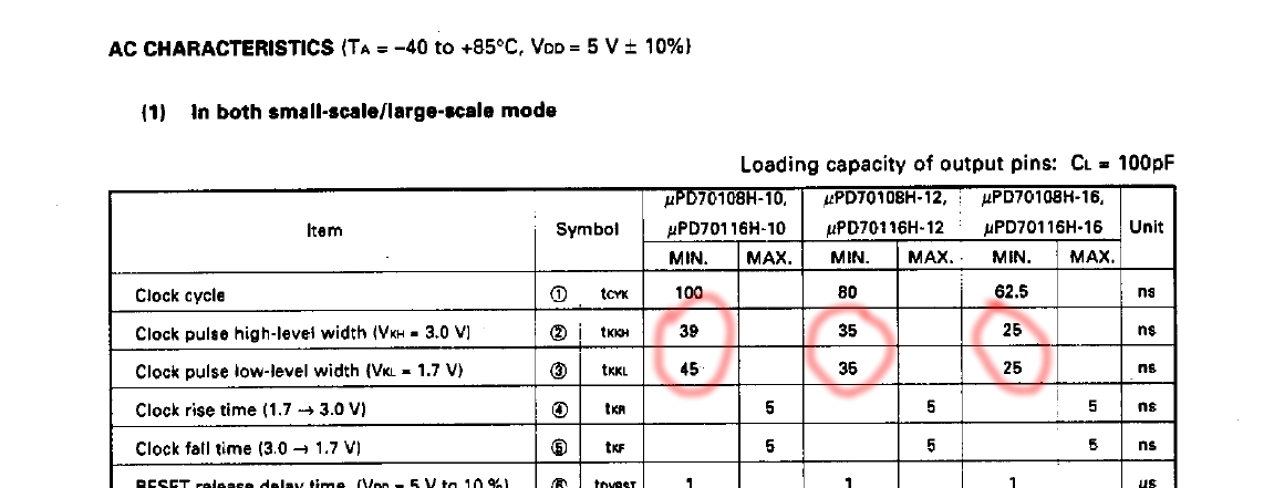
In the Files section you can find the V20HL Datasheet.


RAM CONFIGURATION

The V20-MBC allows three different RAM configurations:

  • 128KB (1x128KB)
  • 512KB (1x512KB)
  • 1024KB (2x512KB)

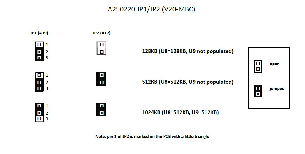
To set the proper RAM configuration two jumpers (JP1/A19 and JP2/A17) must be set. This operation must be done when the board is not powered, and before the first power on with the RAM chips installed.

Please note that using a 128KB SRAM only the single SRAM chip configuration is supported (the 2x128KB is not supported).

The following table shows how to set jumpers JP1 and JP2 for the three RAM configurations:

CONSIDERATIONS USING AN 80C88 CPU

The V20-MBC can use an 80C88 CMOS CPU too.

Of course when using an 80C88 CPU you loose the 8080 mode specific of the V20HL CPU.

Please consider that when using an 80C88 a speed grade -2 is required (80C88-2) to meet the 80C88 specifications. If we see at the datasheet the clock requirements are:
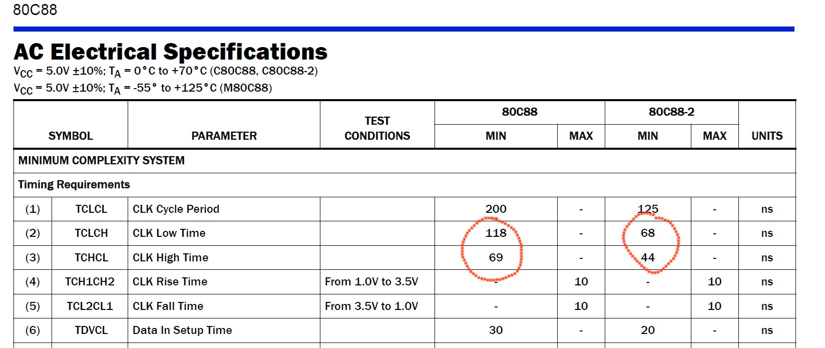
So a 8MHz clock with a 50% duty cycle will no meet both the 80C88 and 80C88-2 specifications, but a 4MHz clock with a 50% duty cycle will meet the 80C88-2 specs.

So you have to use an 80C88-2 CMOS CPU setting the clock at 4MHz...

Read more »

S260320-R241023_IOS_V20-MBC.zip

The sketch for the IOS (with the needed libraries). Unzip into a folder and open the .ino file (with Arduino IDE). IOS must be uploaded into the Atmega32A flash. Added MSDOS support. See the Changelog in the .ino file. The Serial port default speed is 115200 bps (8N1).

Zip Archive - 42.94 kB - 11/04/2023 at 12:35

Download

S260320-R241023.ino.with_bootloader_atmega32_16000000L.hex

The sketch for the IOS in executable format (.HEX) with the bootloader. This executable file is intended for use with a programmer as the Atmel Ice or AVRISPmkII or others (Fuse bits: High Byte 0xD6, Low Byte 0xAF, Lock Byte 0xCF)

x-hex - 62.91 kB - 11/04/2023 at 12:36

Download

SD-S260320-R241023-v1.zip

The content of the microSD for IOS S260320-R241023. Added the SPP Adapter board support for CP/M 2.2 and CP/M-86. See ChangeLog.txt inside the SD image.

Zip Archive - 5.07 MB - 11/04/2023 at 12:35

Download

A250220 - SCH.pdf

Schematic.

Adobe Portable Document Format - 221.90 kB - 04/21/2020 at 11:27

Preview

A250220 - Gerber.zip

PCB gerber files.

Zip Archive - 481.69 kB - 04/21/2020 at 16:10

Download

View all 10 files

  • How use the ISP port with the USBasp programmer under linux to burn the bootloader

    Just4Fun04/28/2024 at 16:18 0 comments

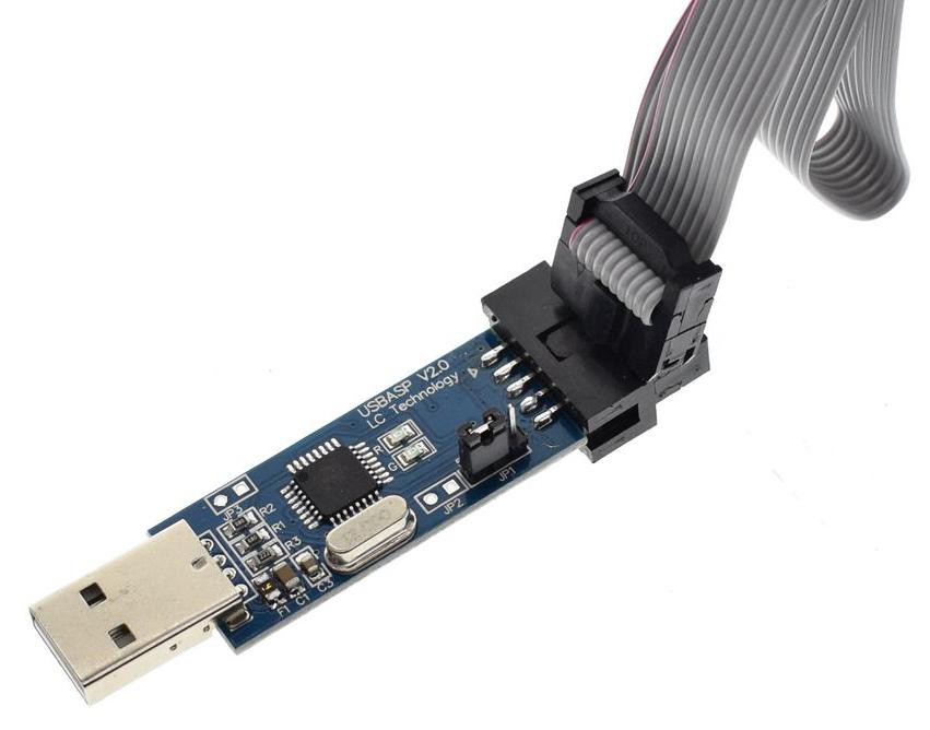
    A cheap and easy way to burn the Arduino bootloader is to use an USBasp programmer that is commonly available:

    The USBasp is also capable to give the power to the "target" using the VCC pin, but remember to check that the JP1 jumper is set to provide 5V to the target (as shown in the photo).

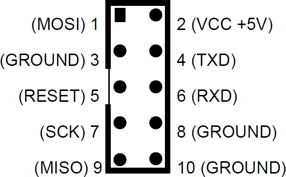
    Please note that the pinout of the USBasp is a little different from the "standard" ISP pinout:

    In the previous picture it is possible see that pins 4 (TXD) and 6 (RXD) are not at GND as expected  by the standard ISP port, and pin 3 is not NC.

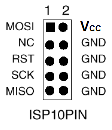
    See the following picture showing the standard 10 pin ISP pinout:

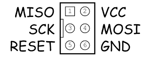
    So you must consider this when connecting the USBasp to the 6 pins ISP port (J2) on the V20-MBC (see the schematic):

    To avoid problems I suggest to use as GND pin 10 of the USBasp connector, and connect the other pins (VCC, MISO, MOSI,SCK, RST) accordingly. An handy way to connect the USBasp to the 6 pin ISP port (J2) of the V20-MBC could be to use a commonly available "10pin to 6pin" adapter like this:

    but I suggest not to use it "as is" because its internal connections are done for a "standard" ISP port, and we have seen that the USBasp connector differs from the standard one. The schematic of the adapter shows that isn't compatible "as is" with the UABasp connector:

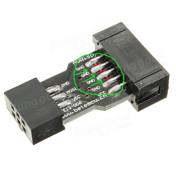
    To use it is a good idea isolate the pins 4, 5 and 6 cutting the trace on the PCB of the adapter that connects those pins together, and then check with a tester. In the following photo are shown the three cuts (thin red lines inside the green "circle") to do:

    BURNING THE BOOTLOADER FROM ARDUINO IDE:

    To easily burn the bootloader follow these "quick and dirty" steps (tested on a linux Mint OS with Arduino IDE 1.8.5):

    STEP 1: Connect the 10 pins connector of the USBasp programmer to the 6 pins ISP port (J2) of the V20-MBC (using wires or a modified adapter as discussed before);

    STEP 2: Verify carefully that any other connector of the V20-MBC is not used, and verify that both the SD and RTC modules (if present) are removed from the board;.

    STEP 3: Only at this point connect the USB side of the USBasp programmer to an USB port of your workstation;

    STEP 4: Open a "terminal" window on your workstation and go to the directory where there are the Arduino IDE executables, and get the root privileges with the command:

    sudo su

    then run the Arduino IDE with the command:

    ./arduino

    STEP 5: Because Arduino IDE is running as the root user it is necessary re-install the "core" for the Atmega32. Open the Board Manager as you already did (anyway  the guide is here). Note that you must do this step only the first time you execute the Arduino IDE as root;

    STEP 6: Now from the Tools menu of Arduino IDE select "Atmega32" as "Board", "16 MHz external" as "Clock", and "USBasp" as "Programmer". Then you can burn the right bootloader (without playing with the FUSE setting) selecting "Burn Bootloader" from the same "Tools" menu.

    All done!

View project log

Enjoy this project?

Share

Discussions

M. Kuperberg wrote 05/24/2024 at 18:35 point

I read Just4Fun's reply to my review of the product. His comments speak for themselves and are consistent with  his level of professionalism.

  Are you sure? yes | no

Just4Fun wrote 05/25/2024 at 09:03 point

I'm not going to follow your path. Anyone here can read and make their own conclusions.

Best regards.

  Are you sure? yes | no

M. Kuperberg wrote 09/29/2023 at 23:02 point

Yes, I built this and finally got it working. It took considerable finagling.

Criticism:

This project should be considered a beta version, as the serial port is non-standard and the build instructions are pretty much non-existent. Fix the serial port and add much needed documentation, including BOM and detailed build instructions.

Notes:

The V20HL is hard to find - doesn't come up in an eBay search, though there is one eBay seller that has them. Haven't tried the non H version of the V20, though others report that it might work. A cheap T48 XGecu EPROM programmer is helpful for programming the ATM32 chip (be careful to set the fuses and lock byte correctly, see comment below).

The SD card interface seems to be fussy about which SD cards it accepts. A 16 GB / 10 speed one works.

  Are you sure? yes | no

Just4Fun wrote 05/21/2024 at 11:06 point

Hi, I've spotted your comment only now, and given the tone you used I have to give a clarification.

This is not a kit for beginners, with all of its aspects explained, clarified and simplified in little steps, and with all the needed parts ready to use, labelled and sorted.
In any case a ready to build kit or assembled unit is available from the seller I've mentioned if you don't want or aren't able to find the needed parts.
It seems to me you are claiming for a "service" that is simply not due.

Some more clarification.
In the "Files" section there is the BOM you are asking for, and in the "THE SD IMAGE" chapter is explained what type of SD card must be used.
But may be you are too busy to read that, and is probably easier complaining not to find it.
About the "non standard serial port" please explain to me what is a "standard" serial port for you.

Best regards.

  Are you sure? yes | no

Keith wrote 05/25/2024 at 13:31 point

I had a look on eBay just now and there are plenty of V20 chips around, in a range of prices. They are also cheaper in QFP form.

  Are you sure? yes | no

John Borland wrote 09/11/2023 at 18:04 point

hi, enjoyed building but having an issue. After the message "v20 cpu running from now"  it just seems to hang. checked sd card and tried another cpu but still cant get past it to  command  prompt off some sort. Any Ideas???

  Are you sure? yes | no

Just4Fun wrote 09/13/2023 at 08:06 point

Some ideas:

* JP1/JP2 setting wrong;

* Wrong FUSE setting when flashing the Atmega (Fuse bits: High Byte 0xD6, Low Byte 0xAF, Lock Byte 0xCF);

* Bad RAM chip(s);

* Bad soldering.;

* A bad day...

  Are you sure? yes | no

John Borland wrote 09/15/2023 at 16:23 point

looks like it might have been ram, stuck an equivalent 128K ram chip in and booted up without issue

  Are you sure? yes | no

zpekic wrote 03/25/2023 at 00:11 point

Cool project! Right now I was just skimming a bit through the V20HL data sheet. If I understand correctly, it can actually natively execute 8080 code? I also saw it has IX and IY registers, does that mean it supports Z80 instructions too?

  Are you sure? yes | no

Ken Yap wrote 03/25/2023 at 05:19 point

Unfortunately V20 doesn't support the Z80 superset of 8080 instructions.

  Are you sure? yes | no

Adam wrote 03/23/2023 at 16:39 point

So I installed the latest IOS and I can see on the screen that the right IOS is installed. I downloaded the SD card and extracted it then deleted my old card and copied over the new files. 

I am getting the following error:  ISO: SD error 2 (NOT_READY on MOUNT operation.

The file names below are what I am using. Am I doing it wrong? I did try to select different Disk Sets but that did nothing. I tried to format with FAT16 and FAT32, nothing. 

My boot screen shows...

V20-MBC - A250220

IOS - I/O Subsystem - S260320-R250223

I feel like maybe the V20-MBC - A250220 might be the problem. Maybe I did something wrong. If anyone can help please.

Regards,


Adam

SD-S260320-R250223-v2.zip

S260320-R250223_IOS

  Are you sure? yes | no

Ian wrote 03/24/2023 at 21:40 point

Hi Adam

Start with the simple stuff. 

First off, check that the SD card reader module is correctly plugged in - I know, but it's worth checking :)

Then download the official SD Association card formatter from https://www.sdcard.org/downloads/formatter/ and format the card with that. Copy the contents of the SD-S260320-R250223-v2.zip file to the SD card with FastCopy (https://fastcopy.jp/) or any other software that can be configured to verify file writes.

If you still get the same error, try a new SD card.

Regards,

 - Ian

  Are you sure? yes | no

Joe Smith wrote 02/11/2023 at 22:56 point

How about a BOM for  this project

  Are you sure? yes | no

Just4Fun wrote 02/12/2023 at 10:46 point

The BOM file is in the Files section ( https://cdn.hackaday.io/files/1709247312812416/A250220%20-%20BOM%20v3.ods ). How about reading carefully *all* the docs... :-)

  Are you sure? yes | no

Tonata wrote 07/25/2022 at 12:39 point

You try a 16 bit linux: https://github.com/jbruchon/elks/issues

Works well.

  Are you sure? yes | no

mobra66 wrote 09/02/2021 at 19:09 point

If you want a slightly newer version of CP/M-86 Turbo Pascal than the 3.00B which is shipped on the SD card, I found a working image of Turbo Pascal 3.01A on this web page: https://rc700.dk/software.php?name=RC750_TurboPascal_v3.01a - remember to run TINST.CMD to select a proper terminal (most likely you want ANSI).

  Are you sure? yes | no

Just4Fun wrote 09/07/2021 at 09:23 point

Thanks for the info.

BTW: Do you know how extract the .img file?

  Are you sure? yes | no

mobra66 wrote 09/07/2021 at 15:45 point

The following diskdef works with CPM tools:

diskdef rc759
  seclen 1024
  tracks 154
  sectrk 8
  blocksize 2048
  maxdir 512
  boottrk 4
  os 3
end

  Are you sure? yes | no

Just4Fun wrote 09/07/2021 at 16:49 point

Thanks!

  Are you sure? yes | no

Mike C wrote 08/10/2021 at 19:21 point

I'm making an emulator for this system. The AVR side is only HLE for now, and the 8080 emulation on the V20 isn't working yet.

https://i.imgur.com/oWQsbVJ.png

  Are you sure? yes | no

Thierry Supplisson wrote 08/18/2021 at 00:18 point

Do you plan to share the code?

  Are you sure? yes | no

Mark Morgan Lloyd wrote 03/25/2021 at 10:15 point

Like a number of other people here, I wrote an emulator in the 1980s so that a V20-based system could run CP/M-80 programs. However, I was working with CCP/M-86 rather than CP/M-86, and the taskswitching showed up a nasty silicon-level "erratum": one of the status flags isn't preserved when the chip switches from (I think) 8- back to 16-bit mode.

  Are you sure? yes | no

steve hunt wrote 03/24/2021 at 14:48 point

I've modified the V20CBIOS source to allow this device to automatically execute either CP/M-86 or CP/M-80 programs without the need of the VCPM emulator program that I wrote back in the 80s.  If the program is a .CMD it'll execute as normal, and if it's a .COM it'll load it into an 8080 environment and then execute it.  The modifications also adds a SAVE command that allows saving pages from the 8080 memory bank.  The SAVE command is only available following execution of an 8080 program and only if the 8080 memory bank is still available. 

The modified V20CBIOS source code (and the compiled cpm86.bin binary file which is ready to copy to your SD card) can be found here: 

https://github.com/binaryspider/v20-mbc_cpm8680_cbios

  Are you sure? yes | no

Just4Fun wrote 03/24/2021 at 15:45 point

Thanks you very much! It is amazing to meet the creator of the VCPM utility here!!! Thanks again for sharing.
So the V20-MBC with your changes is probably the only implementation that can run both CP/M-80 and 86 at the same time...

  Are you sure? yes | no

steve hunt wrote 03/24/2021 at 17:28 point

You’re welcome :-)

There were other systems that could do similar back in the day, but they were typically expensive dual processor computers.  Those I worked on at LSI Computers, the CAL-PC, LSI-Model Four and LSI-Octopus, all had 8088 and Z80 CPUs in order to run CP/M-86 and CP/M-80 programs.

  Are you sure? yes | no

gkaufman wrote 05/24/2021 at 15:12 point

What a great little system, a tremendous thanks to both Fabio and Steve. 

Very similar to the CompuPro 8085/8088 dual processor system in a tiny footprint.

  Are you sure? yes | no

Just4Fun wrote 03/24/2021 at 17:54 point

Just added a paragraph on your implementation:

CP/M-86 WITH AUTO-SWITCH TO CP/M-80

  Are you sure? yes | no

mobra66 wrote 10/24/2021 at 12:37 point

Excellent work. Makes it so much easier to work with the combined tools of CP/M-80 and CP/M-86. Thank you!

  Are you sure? yes | no

Ruud wrote 03/16/2021 at 18:59 point

I found a BASIC program to read out the RTC. How do I set the RTC using BASIC? Is there a document that explains the possible further use of IN and OUT?
Thank you in advance!

  Are you sure? yes | no

Just4Fun wrote 03/22/2021 at 12:52 point

No, from Basic you can only read the RTC. The RTC setting can be done only using the "Boot system menu".

For more info on IN and OUT in Basic you have to become familiar on how the Opcodes work. See the comments in the .ino source file in the "Virtual engine" part.

See also the basic examples.

  Are you sure? yes | no

Ruud wrote 03/24/2021 at 14:26 point

I had a look at the INO and that made me clear that there was nothing provided to set the RTC in BASIC or even ML. But if one changes the INO, a lot can be done. Nice challenge. Thank you for the pointer!

  Are you sure? yes | no

coopzone-dc wrote 01/14/2021 at 20:44 point

Hello,

Can someone give me the steps to compile the cp/m-86 BIOS please. So far i have copied the source code to drive F: and can run a:asm86 bios.z86, this gives several files including a .h86 file that i can convert to a .cmd file with a:gencmd bios. But how do i get the cpm86.bin file?

And do i have to write this to the first track on the boot disk? if so how?

Thanks for help.

  Are you sure? yes | no

coopzone-dc wrote 01/21/2021 at 18:46 point

I have worked out how to do both the cpm-86 and cpm-22 version of the bios with the help of Just4fun, many thanks.

if you would like to know how try:

https://www.instructables.com/V20-mbc-How-to-Build-a-Custom-Cpm-22-BIOS-Windows-/

and

https://www.instructables.com/V20-mbc-How-to-Build-a-Custom-Cpm-86-BIOS-Windows-/

have fun

  Are you sure? yes | no

Scott wrote 05/03/2021 at 22:28 point

I see you are running TASM under a WINDOWS 10 virtual machine to perform this function. I assume you are developing in a Linux environment. Like you, I also run a WINDOW XP virtual machine for SOME older development software like AVR STUDIO 4.19sp3. In this case, since TASM v3.2 is a WINDOWS executable, it will run using WINE under Linux. I know because I have done so, particularly with TASM v3.2. This saves a LOT of time and hassle with using WINDOWS dev-tools under Linux.

I've done the same with DOS-based tools like Dave Dunfield's assemblers using DOSBOX. Set up a BASH script and add the drives, etc. 

WINE, QEMU and DOSBOX work very well and I think many of us are very blessed to have them and Linux and ALL the developers of Linux/Linux tools doing all the wonderful things they do and support they bring ALL the time. 

Peace and blessings,

JQ

  Are you sure? yes | no

sq9pxb wrote 11/30/2020 at 19:44 point

Hello!

I try to use for this great project Intel 8088 proc (not CMOS 80C88), and its work fine!

See and sorry for low quality : https://www.youtube.com/watch?v=P69ItijqUvk

Regards,

SQ9PXB

  Are you sure? yes | no

Jacques wrote 07/27/2020 at 01:57 point

Completed the assembly with NEC D70108C-8 CPU and work without any problem at 8Mhz. For now only tested CP/M-86.  Notice that the specifications for the NEC D70108C-8 are   

clock pulse High level minimum width is 44 nsec

clock pulse low level minimum width  is 60 nsec  

  Are you sure? yes | no

freefuel wrote 07/10/2020 at 13:39 point

allow me to apply some arm twisting, if we ask very nicely can we have an ISA card version of this for use in a passive backplain? 

  Are you sure? yes | no

Ken Yap wrote 07/11/2020 at 01:43 point

I doubt it because it would be a total redesign to bring out the buses to fingers, add transceivers, and all that guff. Return that ISA bus to the museum you took it from. 😉

  Are you sure? yes | no

Aaron wrote 01/27/2021 at 01:05 point

well maybe not the twisting you wanted but atleast there is maker of the ISA stuff and no ISA is not dead especailly when it gets used in PC104 stuff. Not ready for the museum as of yet.....

https://github.com/skiselev/micro_8088

https://www.ebay.com/usr/fmv.electronics1?_trksid=p2057872.m2749.l2754

  Are you sure? yes | no

guus.assmann wrote 10/28/2021 at 14:47 point

This is already old, I know.

I made a PCB with a card-edge connector that fits the 8085-SBC as designed by Craig Andrews. This has a passive backplane.

So it's not ISA but it has all signals to the bus. And it also works at 10Mhz, with some changes in the ATMEL program. It may need some more small changes, to have some inputs on passive pull-ups instead of active pull-up by the Atmel.

If you want the layout files. let me know.

  Are you sure? yes | no

RW wrote 06/06/2020 at 13:15 point

You seem to be saying a 80C88 -2 is needed for 4Mhz, when I do the math, reciprocal of double the minimum low time for 50% cycle... I get ~7.3 Mhz for the -2 and ~4.2Mhz for the plain Jane. Still processing the deets, but not sure how it needs 70ns RAM either, since 120 should be good over 8Mhz, or is the ATmega writing to it faste?

  Are you sure? yes | no

Just4Fun wrote 06/06/2020 at 13:52 point

I've added 10ns for the rise and fall time, so the minimum period (50% duty cycle) for the 80C88 is (118ns + 10ns)*2 -> 3.9MHz.

About the RAM speed grade the 70ns is only that one I've used because it is cheap and  easy to find on ebay... A 120ns one should be fine as far as I remember (yes... the phrase I've written can be misleading in this case...)

  Are you sure? yes | no

RW wrote 06/06/2020 at 14:37 point

Ah right, thanks. Guess even if you condition it with fastest through hole logic it's still 5ns. However, I'll assume the engineers left themselves 5% wiggle room and 99% of the "-1" parts will work. I'll have to try deciphering the date code on mine (Harris) and if it's not in the first few months of production, it should be good. If it isn't, give it another .5V and try again LOL. Particularly as Harris seem to have super good processes (They put out 25Mhz 286s etc). I think I saw a simple way to fiddle the duty cycle also, will look into that. 

Edit: Hey wow, an edit button. So checked out mine, seems to be 3 years into production, so I would hope they got them well tuned by then. Oddly though, there's a slight scuff on the package where they'd put the -2 or -10 -12 etc, and the scrap industrial control board it's sitting on has a 12Mhz crystal, all the other parts seem fast enough for 12Mhz too. So I don't know if it is a "-1" and that clock is divided in 3 or 4, or it's clocked at 6 with some duty cycle modification, or whether it was deliberately scraped off because they put a -10 on a 12Mhz board. Was made in 1986, so I think there was a huge enough price difference between speed grades then still that A) They wouldn't use 12Mhz capable parts on a board that ran half that speed B) they might have tried to save $20 on the 10 instead of 12.

Edit2: "Pulse stretcher" is what circuits are called that can modify the duty cycle of a clock pulse.

  Are you sure? yes | no

villaromba wrote 06/05/2020 at 16:02 point

CP/M 86  = Perfect !!! Thankyou.

BTW XMODEM fully working, for whatever reason SERIAL_RX_BUFFER_SIZE in HardwareSerial.h  had gone back to original values. When I looked at the .INO I realised IOS:

'Found extended serial Rx buffer' was not being shown ...... it all came back to me from SBC days....  it's an age thing!!!!

  Are you sure? yes | no

Just4Fun wrote 06/06/2020 at 09:05 point

Great!

BTW: If you update the MightyCore library you will loose yours changes...

About XMODEM: I haven't found a XMODEM version for CP/M-86. If you found one let me know...

  Are you sure? yes | no

villaromba wrote 06/06/2020 at 12:09 point

Will seek !  

http://www.eolith.co.uk/mirrors/cpm86/files.htm  holds some interesting programs including Forth 83 which I transferred &  seems to work ok. Also some working File/Directory utilities  e.g  nsweep.cmd, sd.cmd. Much for specific IBM pc but will look through some of the others programs. Documentation good.

  Are you sure? yes | no

Scott wrote 06/13/2020 at 03:29 point

I have recently been working with CP/M-86 (V1.1 for PC) using QEMU as a virtual (PC) machine (as a fork off from the V20MBC project). I was able to successfully interact with the VM via a serial port (AXI and AXO) set up to be a UNIX socket, which then used SOCAT to translate it to a virual serial port for PICOCOM, which used the external SX and RX programs under Linux. I too found there was no XMODEM-86 available for CP/M-86 nor is there a CP/M-86 KERMIT available for the IBM PC/XT machines. However, I found MODEM9 (MODEM 7 fork from CP/M-80), which does use XMODEM for U/L and D/L. It can be found here https://www.z80cpu.eu/mirrors/klaw/86comm.zip. I'm sure that it can be slightly modified to work on the V20MBC since all I/O is done through the CON: device. The CP/M-86 ASSIGN utility may be used to remap logical and physical device I/O as well.

Peace and blessings,

JQ

  Are you sure? yes | no

Scott wrote 05/27/2020 at 07:18 point

Ordered PCB from eBay vendor out of TEXAS. It arrived today. Build was non-traumatic. 

I couldn't find the ATmega32 fuse settings anywhere in the project files. Might be helpful to add them to the IOS source code for reference. I ended up using lfuse:0xFF and hfuse:0xC6

All I have on hand is older 8088's from AMD (DC: 1978) and an INTEL. 

The V20 I have is D70108C-10, which is not the D70108H that was said to be required for this board. **However, the D70108C-10 works fine.**

Idle current is about 70ma. Active current peaks at just under 100ma.

XMODEM: running V20 at 8MHz was successful with U/D load of 1MB file.

Since the Z80MBC2 supported QP/M 2.71, I copied those disk images over to the SDcard but had to modify the IOS source code to allow 2 disk sets rather than just 1 as is current config and add the DEFINES from the Z80MBC2 source code. Weird because QP/M loaded the 1st time but it will not load any longer.

CP/M 3 and PASCAL would not load. I did not look into the reason(s) why. CP/M 3 is likely due to banking set TRUE.

Right now, the V20MBC is a glorified 8080. Any chance to get some 8088/8086 code running on it? CP/M-86 is available but seems very limited.

J4F - thanks again for another great "hybrid-retro" design. I love the "new" instruction stuffing method used since Z80MBC2.

Peace and blessings,

JQ

  Are you sure? yes | no

Just4Fun wrote 05/27/2020 at 09:40 point

Hi, thanks for the info. If you try to use the Z80-MBC2 CP/M, it contains a BIOS with Z80 specific code that doesn't work with the 8080 mode. The same is for CP/M Pascal. I haven't checked for QP/M.

About 8088/8086 specific code, I'm thinking about it...

  Are you sure? yes | no

Scott wrote 05/27/2020 at 10:13 point

Hi: I figured the issue was Z80 code vs. 8080 code. I just hadn't gone looking through the code for those loaders yet.

It's odd that the QP/M loader brought up CP/M and I retrieved a directory listing of drive A:. Then it never worked again.  Maybe the V20 thought it was a Z80 for a moment then suddenly realized it was an 8080. :)

  Are you sure? yes | no

Just4Fun wrote 05/27/2020 at 10:20 point

About QP/M, also its BIOS uses Z80 specific code (it is very close to the CP/M one).

  Are you sure? yes | no

Scott wrote 05/30/2020 at 20:21 point

Yes, the Z80-MBC2 loaders are all Z80 mnemonics.  I may take the time to modify at least the QPM files.

I know, there's not much code available for 8088/8086 single board computers. It's all DOS or PC BIOS related. Sigh... :)

With some effort, Dave's  MON-85 monitor may be modified to work with [s]8080[/s] 8088 code, which would be good since MON-85 allows one to set and use up to 8 software breakpoints.

Peace and blessings,

JQ

  Are you sure? yes | no

Just4Fun wrote 05/31/2020 at 09:22 point

MON85 for the V20-MBC is already available in the /8080 folder... (see the DETAILS section...)

  Are you sure? yes | no

Scott wrote 05/31/2020 at 19:07 point

Sorry, my prior post should have stated "8088", not "8080". :(

Yes, MON-85 for the V20 running in 8080 mode. I was talking about mods to bring it up to 8088 usage, so "MON-88". 

As I recall, there are translators for 8080 to 8086 mnemonics. Would be interesting to see MON-85 run as "native code" on the 8088. :)

Peace and blessings,

JQ

  Are you sure? yes | no

mark.e.riley wrote 07/25/2020 at 07:26 point

Do you want a hand?  I'm going to fork this anyway so that I can use an ATMega1280(p) :-)

  Are you sure? yes | no

villaromba wrote 05/23/2020 at 09:49 point

Just loaded the new revision with XMODEM  and replaced the SDCard files. When I run XMODEM it just hangs.... All OK or you ??

  Are you sure? yes | no

Just4Fun wrote 05/23/2020 at 10:51 point

Tested now and it seems that it doesn't receive... strange because I've tested it a few days ago and worked in both directions... Hmmm...

  Are you sure? yes | no

villaromba wrote 05/23/2020 at 11:15 point

Try @ 4Mhz, it works for me at lower rate....

  Are you sure? yes | no

Just4Fun wrote 05/23/2020 at 11:12 point

it seems that only very little files can be received... strange because I've tested it with big files (500KB) in both ways without any problem... but not working now...

  Are you sure? yes | no

Just4Fun wrote 05/23/2020 at 11:33 point

No differences for me @4 or 8MHZ. I can send and receive a 190 blocks file as MBASIC85.COM but if I try to receive a big file (about 500KB) it closes the receive session without receiving nothing. This is very strange as I've tested it without any problem with big files... and I haven't done any change...

  Are you sure? yes | no

villaromba wrote 05/23/2020 at 11:44 point

Just dumped a 1200Kb .txt file over (took 6.18mins) but went over without a problem.

BTW I'm running an ATMega32, In theory I think it should be ok  but I will burn a Mega32A just in case !!! 

OK: With Mega32A no difference, nothing at 8Mhz  all good at 4Mhz

  Are you sure? yes | no

Just4Fun wrote 05/23/2020 at 12:00 point

So @8MHz you can't transfer any file (little or big) and @4MHz every file (little and big) without any problem?

  Are you sure? yes | no

villaromba wrote 05/23/2020 at 12:06 point

@8MZ a  5Kb file hangs at 2.7% xfer. Everything seems to work @ 4Mhz. Just xfrerred Zork 1, 2 & 3 over too without any problems

  Are you sure? yes | no

villaromba wrote 05/23/2020 at 12:20 point

ok A little more info e.g with XMODEM ZORK1.DAT /S,  a send - works @8 & @4 Mhz just the /R that seems to be the problem at 8Mhz

  Are you sure? yes | no

Just4Fun wrote 05/23/2020 at 12:16 point

WAIT!!!! All previous (my) problems are fake!!!!

I was using a corrupted (big) test file inside my VM!!! (OMG!!!)

Now it is all working @4 and 8MHz with every kind of file (little and big) in both ways... (as during my previous tests).

So no little bad ghost inside my V20... :-)

  Are you sure? yes | no

villaromba wrote 05/23/2020 at 12:23 point

Well that's good news (I think!!!) - I can live with  Xmodem @ 4Mzzzz it's not used that much any rate. Next week I should complete my 2nd build. Be interesting to see how that does.

BTW Thanks for all the  tests and updates......

  Are you sure? yes | no

Similar Projects

Does this project spark your interest?

Become a member to follow this project and never miss any updates