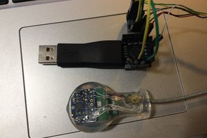
The sensor itself consists of a 3D printed venturi tube with a PCB mounted on top of it.
A venturi tube is a simple type of flow sensor. It's basically a tube with a constricted center portion. As air flows through the tube it is forced to speed up as it passes through the constricted throat of the tube. This increase in speed comes with a decrease in pressure. By sensing the air pressure both at the entry to the tube and at the throat of the tube the flow rate of the air passing through the tube can be determined.
A PCB is mounted on top of the venturi tube. This PCB holds the following main components:
- Processor. I'm using an ARM processor made by ST (STM32 family)
- Pressure sensors. There are two sensors mounted to the bottom of the board which sense flow in the venturi tube
- OLED display. This is used to display current pressure/flow rate information when the device is being used in stand alone mode. The data is represented both in text form and as a moving graph at the bottom of the display
- Rotary encoder. This provides a knob that can be used to switch between screens of the display and enter limits for monitoring.
- Buzzer. A magnetic buzzer is used to alert medical staff in the event that the flow rate or pressure exceeds the limits entered.
- Communication interfaces. Both RS232 and USB ports are available for connecting the flow sensor to other equipment.
All design files are available in the github link below.
Additionally, a video is linked below which shows the results of some initial testing of the sensor. Results have been very promising.
 Steve Glow
 oneohm
 DIY GUY Chris
 chris.coulston
 CaptMcAllister