Phil Malone
-
Log #5 Going Wireless
04/17/2020 at 19:28 • 0 commentsIn Log #4 I described the process of getting the HUGS protocol running on the hoverboard. Once I had that under control I needed to think about what my first Human Machine Interface (HMI) was going to look like.
My first test platform was going to be a Jenx Multi-Stander, which is basically a complex collection of framework and padding on wheels, designed to provide support and mobility to a young child with minimal muscle strength or control.
I considered different input options, and finally decided on an arcade joystick with limit switches. I chose this in lieu of an analog joystick because a child with reduced fine motor control will not gain much benefit from a proportional controller, and a switch based joystick will be very robust. My ultimate goal is to generate some smart motion profiling based on observed control behavior.
The next question to resolve was should the input device be wired to the hoverboard, or should it be wireless.
Since we live in a wireless world, so I thought I'd run down this road until I hit a roadblock.
The ESP32 supports WiFi and Bluetooth. Bluetooth is cool for low power devices, but once I started looking at the software required to get point-point working, I was a bit discouraged. Then I discovered that Espressif (make of the ESP family) has a pre-built WiFi protocol for interconnecting their chips.
It's called ESPNow, and there is a sample project in the IDF to show how it works. I implemented espnow on two ESP32 dev kits, to see how well I could transmit joystick information wirelessly. The implementation went pretty well, but I ran into other problems.
So far I had been using the 5V supply that the motor controller board was providing to run my embedded HMI processor. This power was convenient because it was one of the pins on the UART cable. Unfortunately whenever the ESP32 started using WiFi, this supply got squirrely (a very technical term). It seems that the ESP was pulling too much current to be supplied from a single motor controller. As long as both of them were powered up, everything worked fine, but during startup or shutdown when only one might be providing power, the ESP got erratic and it would not always recover... This left the hoverboard in a bad state where it would not power up or down properly.
So, in the end I decided that I didn't need wireless that badly, and I decided to go down the tethered joystick road. Although I did not end up using espnow, if you want to see how it works, there is a espnow branch in my ESP HUGS repository.
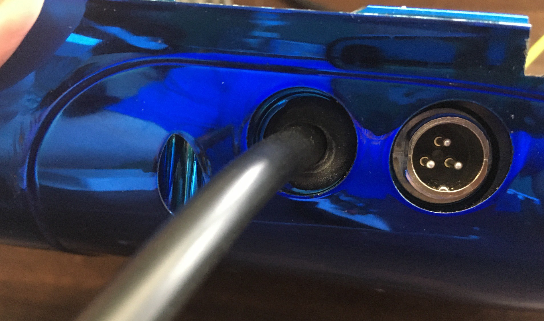
Ultimately I prefer the tethered approach. This way there are no "pairing" issues or loss of control due to interference or low batteries.... and no batteries. You also can't lose the joystick because it's connected. I was able to pull the power switch out of the hoverboard case, and replace it with a rubber grommet that protected the robust 6 conductor cable that I ordered.
![]()
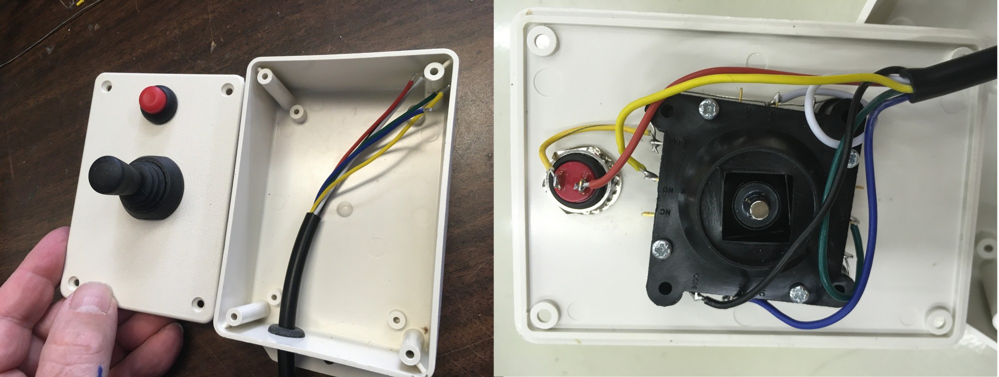
I also decided on a smaller switch-based joystick. I mounted it in a small plastic box, along with the relocated on/off switch. Now I finally had all the controls I needed. Next up is refining the motion controls.
![]()
-
Log #4 Developing HUGS
04/17/2020 at 15:04 • 1 commentHUGS is an acronym. It stands for: Hoverboard Utility Gateway System. Yes, it's a bit contrived, but every project needs at least one cute acronym :)
The idea was (and still is) to modify the Hoverboard firmware, to provide a standard control interface, and provide the opportunity for hobbyists with mid-level tools and skills to use the boards for a variety of drive purposes. I want to keep as much of the standard hoverboard electronics and hardware untouched (or at least un-modified) and then use existing connectors etc. to provide an external control interface. This interface would be used to receive commands from, and send system status back to, a control processor.
The HOVER-1 ULTRA boards have one serial interface that connects the left and right side motor controllers, and so I decided to repurpose this interface for external commands. There are several other serial ports available on the controller boards, but these are exposed as sets of PCB pads that don't have anything connected to them. These can be used as additional ports, but you need to solder header pins to them, and frankly, it's tricky, even for an experiences builder.
It IS possible to reprogram the motor controllers without actually soldering pins to the board, just by pressing the programming header onto the pads, so that was consistent with my goal of not requiring electrical modifications.
So, I started out by creating what I thought would be an efficient control-protocol specification. I wanted to be able to control the speed and position of the drive wheels, as well as being able to enable and disable the controller and get feedback on things like speed, position, voltage, current etc.
I chose a binary packet format (rather than ASCII Text) in order to keep the packets short (and fast). Each variable length packet would contain start and end bytes, variable length data and a checksum. Each incoming command would also request a specific response packet containing sensor or status data. The HUGS protocol would run at 115200 BAUD.
I've included the Protocol Specification in my files list.
When I went to start implementing the HUGS protocol in my deployment test code, I realized that there were a lot of elements in the Lawn Mower code that I didn't need. So to simplify things, I forked a new repository from the original Florian Gen 2 code base. This became the basis for my Hoverboard_Utility_Gateway_System repository.
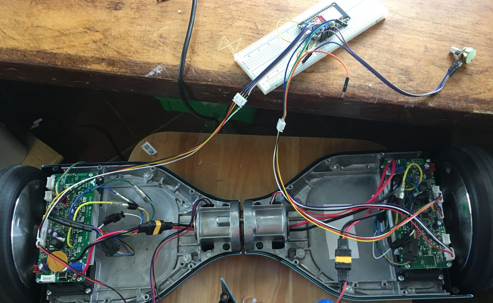
Whenever you develop a protocol, you typically need something to run at both ends to test that it works. In my case my initial plan was to embed an ESP32 based processor into the hoverboard chassis to act as a "Human-Machine Interface" (HMI), so it made sense for me to work on this component simultaneously with the hoverboard firmware.
I grabbed an ESP32 DevKit 1 prototyping module and plugged it into a proto-board and then added some cable headers that matched the cable already being used by the Hoverboard. Instead of a single cable running between the Master and Slave controllers, I needed to run a separate cable from each controller, so my prototype board had both a master and slave connecter.
![]()
The ESP32 it really small and capable with WiFi and Bluetooth, but the reason I chose it over it's little brother (the ESP8266) is that is comes with three UARTs in hardware. One of these is usually dedicated to the download/diagnostics function, which leaves two that can be used to talk to the two motor controllers. You can access these three ports easily with the ESP32-IDE, and with a bit of fiddling with the Arduino IDE. I had just done a major project wit the ESP32-IDF so I used that.
The first HUGS command that I implemented was the SetPower command which just translated into PWM power values of +/- 1000 in the bldc.c code. The new hoverboard firmware accepted the command from the HMI and then responded with the requested status data.
The code for the ESP32 was setup to read a potentiometer and convert the value into power values and send this to the Hoverboard. This way I could get a feel for the performance of the hoverboard code and drive electronics simply be twiddling the pot. I implemented ALL the different response codes, so the ESP was able to sequence through them and display the replies on a serial terminal on the PC, as part of the ESP32-IDF console.
I learned some interesting things while doing this initial testing. Each of the motor controller boards are capable of shutting down their own 5.0V Power supply, but only the board that is connected to the power button can see the request for power on or off. It must pass this information across to the other side via the serial port, so the HUGS interface has to be able to report a "power off" request up to the HMI so it could relay it to the other controller. The obvious question then is how does the other side get turned on? It turns out that the 5V supply form each controller is shared across the serial interface, so if either controller power up, it powers up the opposite side. Thus BOTH sides must hold the power OFF for the electronics to be truly turned off.
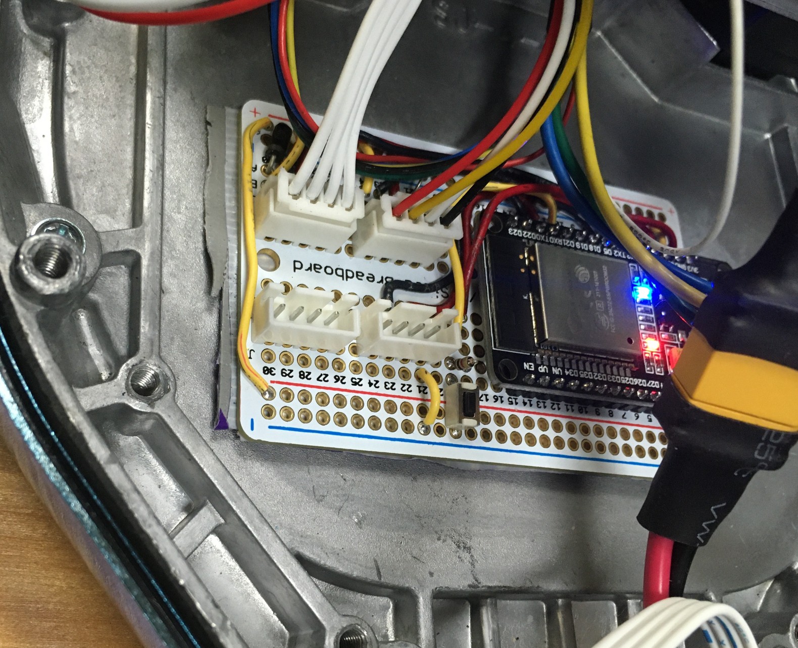
After I had proven that I could run the board from an ESP32 with no problems, I built a wired protype HMI board (vs the solderless proto-board) to make my testing a little less likely to fall apart. At the same time I started a PCB design to send off to PCBway.com
![]()
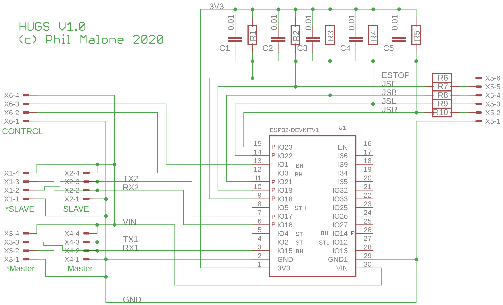
Here are the resulting schematic and board layout.
![]()
![]()
Note that the board has two connectors for attaching to the slave, and two for the master. The two pairs of connectors just have their TX and RX pins swapped. This is to accommodate the type of cable you are using (crossover or straight through). Ultimately the TX line from the ESP32, needs to get paired with the RX line of the Hoverboard controller.
Next, lets think about wireless control.
-
Log #3 Exploring Firmware
04/16/2020 at 17:49 • 0 commentsIn Log #2, I explained how I found the source code I hoped would work with my hoverboard, and how I prepared for developing new code.
The first step was to build and deploy one of the code repo's I had found..
I decided on the Gaucho LawmMower hack, as it seemed to interface to more external devices, and it included more additional support files (like schematics and images).
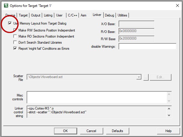
I forked and cloned the repo using Github Desktop. It took a but of tweaking to get Keil uVision 5 to accept the project as cloned, but once I discovered how to overcome one build problem, it looked like it was ready to flash. I didn't record the specific build error that was being thrown (something about a missing map or file ??), but the solution was to change the project setting below.
![]()
The overall project structure is really easy to work with. There were matching .C and .H files, and the number of total files was reasonable. Since it took me a while to get the hang of what the files were doing, here's a quick overview of the ones that interested me the most.
main.c Obviously the main program, but it mainly forms the background error checking function. After sounding the startup tomes, it enters an endless loop checking for error conditions, such as low voltage, high current and inactivity timeout, at which point it sounds an alarm, sets the status LEDS and powers down both boards.
setup.c This module contains the initialization code for all of the hardware interfaces: Timers, GPIO, Interrupts, Watchdog, ADC, PWM & Comm Ports. If you want to see how the code interfaces with the hardware, this is where you need to look.
it.c This module contains the running code for Interrupts and timers (which are based on those interrupts). Most of the code in this module is time critical, so there are no loops of heavy processing. Functions typically set some flags and maybe call a small function, and then return.
bldc.c This module is where all the cool Brushless DC motor control logic exists. The main bldc control function CalculateBLDC() is called periodically. The code says every 62.5 uS, but on the HOVER-1 Ultra, is appears to run twice as often as this, at 31.25 uS. I don't know if this is a configuration error, or perhaps the processor has a faster Crystal, but it's a bonus. The Gaucho code has several motion command functions that I didn't end up using, but these sit on top of the normal PWM power control. The main function of CalculateBLDC() seems to be to determine which drive phases should be active, and what PWM power level is required. The HOVER-1 wheel has 15 phases per revolution, and 6 Steps per phase (my wording). This means that for each revolution of the wheel, you are able to discern 90 transitions (Steps).
commsXxxxxx.c There are several module which have the same file name structure: comms followed by the name of the communications function. Each of these files deals with one of the various serial communications ports. This could be for inter-board communication, diagnostics, Bluetooth or any other purpose. Each instance has a very similar structure. There is a function called updateXxxxInput() which is called based on some interrupt (UART Rx or Timer) which signals that a single input event must be processed. There is also a function called checkXxxxInput() who's job it is to process a completed input buffer and take the appropriate action. I found it very easy to add my own communications using this structure.
It's worth noting that in both of the two code sets that I found, there was the assumption of a master/slave relationship between the two controller boards. The "Master" would determine that some action needed to be taken and it would take that action locally, and then tell the slave to do the same thing. This was done over the MasterSlave comms interface.
In order for single set of source code to be used to generate the binary image for both controllers, there were two compiler #defines created (called MASTER and SLAVE) which were used for conditional compilation. In several files, there are sequences like the following:
#ifdef MASTER
   #define USART_MASTERSLAVE_TX_BYTES 10  // Transmit byte count
   #define USART_MASTERSLAVE_RX_BYTES 5   // Receive byte count
    // Variables which will be written by slave frame
    bool slaveBoardMovementByStepCompleted=FALSE;
#endif

#ifdef SLAVE
   #define USART_MASTERSLAVE_TX_BYTES 5   // Transmit byte count
   #define USART_MASTERSLAVE_RX_BYTES 10  // Receive byte count
    // Variables which will be send to master
    FlagStatus upperLEDMaster = RESET;
    FlagStatus lowerLEDMaster = RESET;
    FlagStatus mosfetOutMaster = RESET;
    FlagStatus beepsBackwardsMaster = RESET;
#endif
Since I just wanted to prove that I could build an deploy the code to one controller, I #defined MASTER and used that generated binary throughout my initial testing.
Later on, when I got around to developing my own code, I wanted both controller boards to be running the same code, so one of the first things I did was to eliminate the MASTER and SLAVE defines, and delete all the slave code. But that's a later story.
-
Log #2 Researching Firmware
04/16/2020 at 14:28 • 0 commentsOnce I received my new HOVER-1 ULTRA, and discovered that it had two separate motor controller boards, I knew I had some research ahead of me.
To cut a long story short, I found two great projects that could help me with code.
The first source was a Software repo by Florian, a German Software and Hardware developer.
https://github.com/flo199213/Hoverboard-Firmware-Hack-Gen2
This appears to be the first code repository that deals with the Dual controller code.
An interesting adaption of Florian's code was made by Gaucho, in Rome.
https://github.com/gaucho1978/CHEAP-LAWNMOWER-ROBOT-FROM-HOVERBOARD
By combining information from both of these projects, I was able to establish a starting point for my own code. I actually used Gaucho's code to verify that I could succesfuly build and deploy working code, but in the end I used Florians code as the basis for my own project.
The Florian Repo came with the following Flashing instructions
-------------------------------------------
The firmware is built with Keil (free up to 32KByte). To build the firmware, open the Keil project file which is includes in repository. Right to the STM32, there is a debugging header with GND, 3V3, SWDIO and SWCLK. Connect GND, SWDIO and SWCLK to your SWD programmer, like the ST-Link found on many STM devboards.
- If you never flashed your mainboard before, the controller is locked. To unlock the flash, use STM32 ST-LINK Utility or openOCD.
- To flash the STM32, use the STM32 ST-LINK Utility as well, ST-Flash utility or Keil by itself.
- Hold the powerbutton while flashing the firmware, as the controller releases the power latch and switches itself off during flashing
--------------------------------------------
So I ordered the ST-LINK interface from AdaFruit.com, and downloaded the Keil software from https://www.keil.com/demo/eval/arm.htm and the ST-LINK Utility from https://www.st.com/en/development-tools/stsw-link004.html
I mounted header pins for programming and serial debugging, and stared down the road of figuring out what the various elements did.
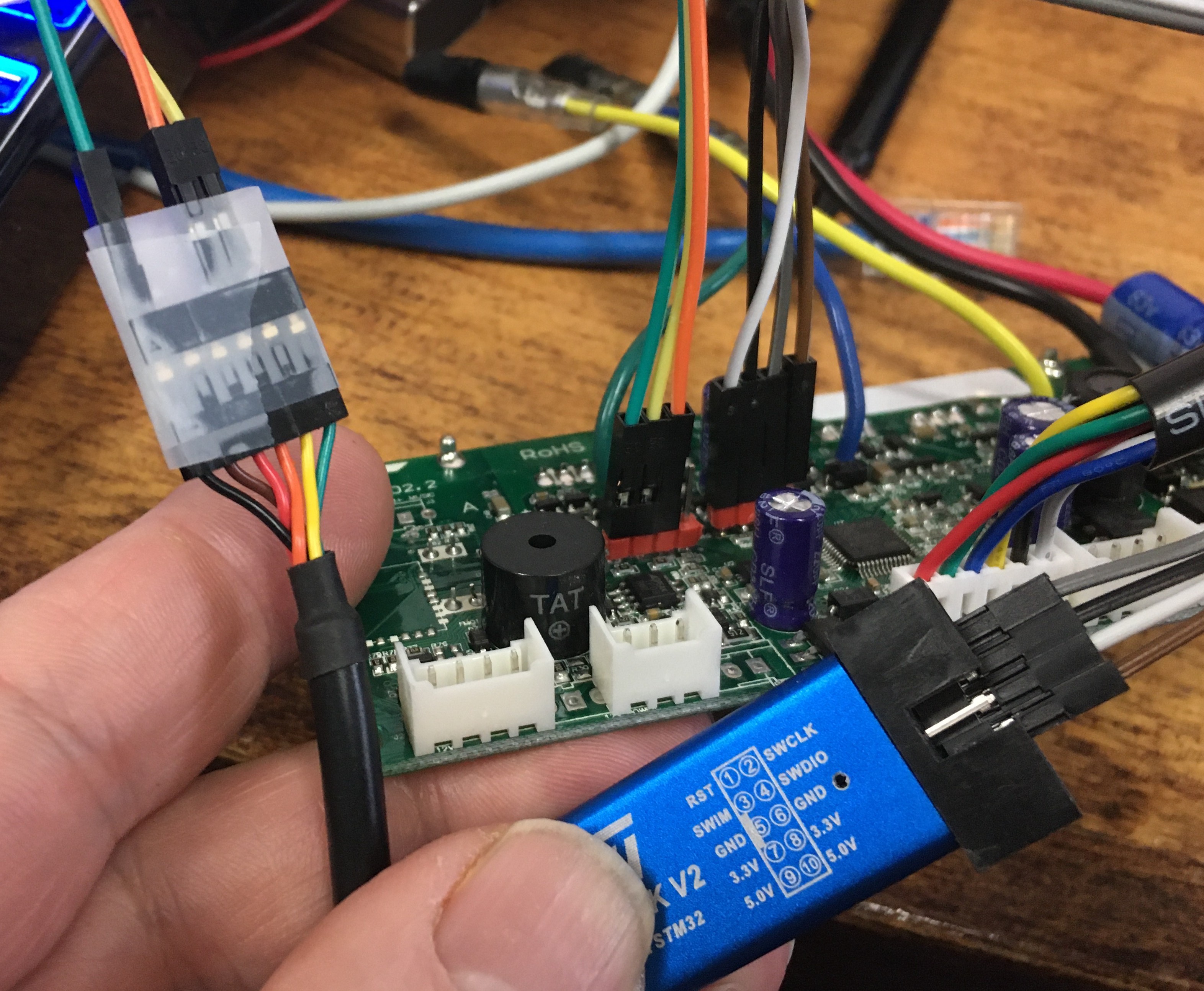
The following picture shows the two cables that I assembled for programming and debugging. The ST-LINK module was connected to the programming header by 4 wires. This provided the communications AND power for the processor. Note: the processor runs on 3.3V (not 5V). Also shown is the serial debugger cable that uses a USB-TTL Serial interface like this one. Note that the power from the debugger cable is not used, and the interface is 3.3-5v compatible.
![]()
-
Log #1 Hardware Research
04/16/2020 at 13:56 • 0 commentsI decided I wanted to experiment with a Hoverboard drive system. I knew they were brushless but that was about it. I've been working with small robot drives and software for 15 years, as part of my involvement with FIRST Robotic teams.
Step one was to get a little smarter about what people had already done. I'd looked several years back, but couldn't find much.
Now I found several projects and Github repos that had code for hoverboards.
https://github.com/bipropellant/bipropellant-hoverboard-firmware
https://github.com/flo199213/Hoverboard-Firmware-Hack-Gen2
https://github.com/gaucho1978/CHEAP-LAWNMOWER-ROBOT-FROM-HOVERBOARD
So, I decided to go and buy a hoverboard to play with. My problem was that I couldn't find a great list off specific manufacturer's, who's boards contained a controller that was compatible with the code that was out there. I found it hard to believe that all boards were similar enough to use the same firmware.
Anyway, I decided to locate a hoverboard supplier that seemed to be be large enough and recognizable enough to provide a consistent product line over time. I settled on HOVER-1 since they had several models and were also available online, and in brick & mortar stores like Best-Buy and WalMart.
I ordered the HOVER-1 ULTRA which was a middle of the road product which sold for $154 online.
Note: I have just found that HOVER-1 is selling reconditioned ULTRA units on EBAY for just $99.
When I opened up the unit I was in for a surprize, because the controller board was NOTHING like what I had found in all the hoverboard Hacking projects. Sigh.... In fact, it was two separate controller boards, located where the gyro boards were in most hoverboards.
Before I just threw my hands up in dismay, I searched further, and found a few code repos that apparently worked with this type of controller board. So rather than try another brand, I decided that smaller independent controller boards might actually be an asset. It meant I could have one board for each motor, which meant I could separate the motors more easily, and one controller failure would not take out both motors.
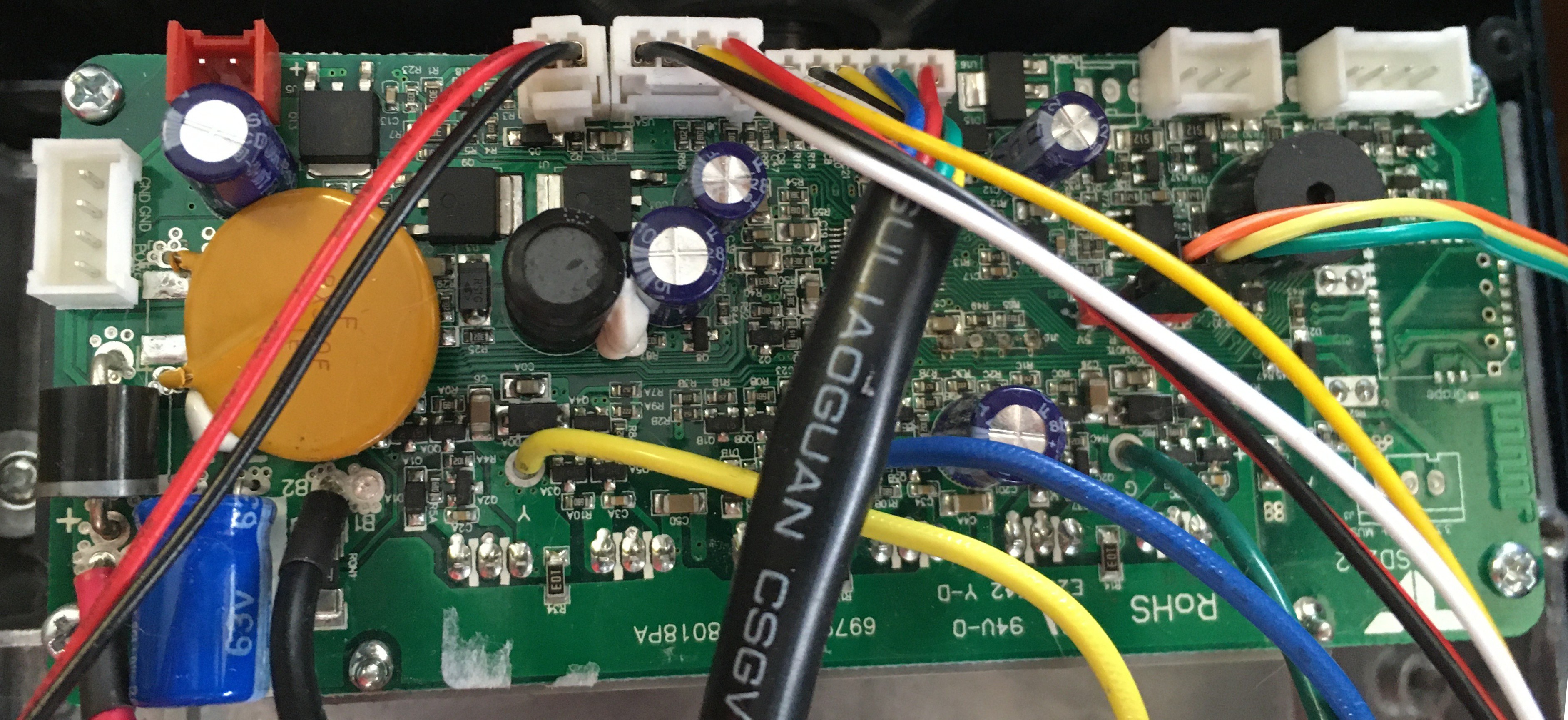
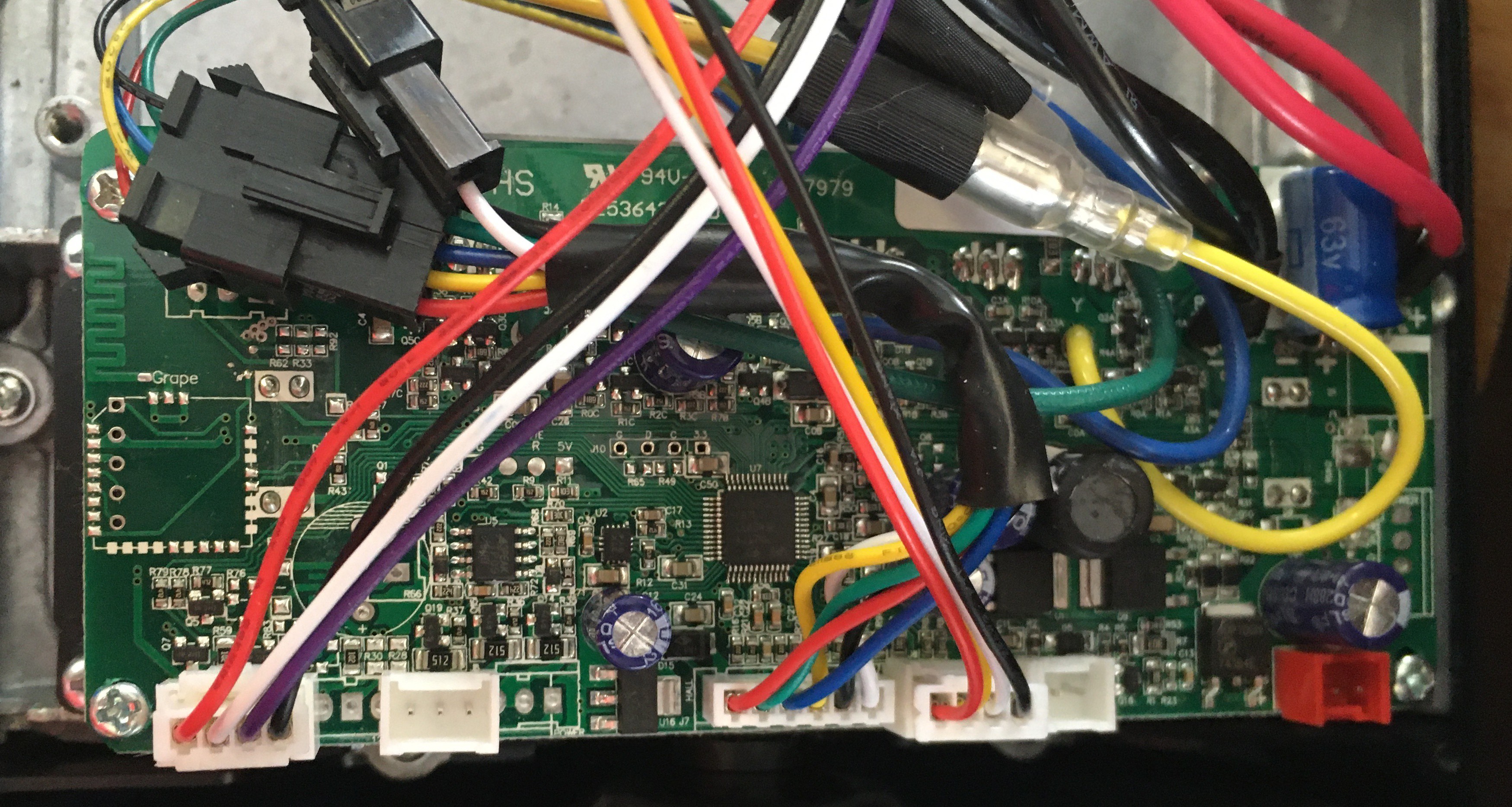
Here are some pics of the two controller boards.
![]()
Master Controller (No battery)
![]()
Slave Controller (Battery Side)
Hoverboards for Assistive Devices
Want to motorize a wheeled assistive device? What better than a hacked hoverboard with brushless motors, electronics and power.