 M. Bindhammer
1. Overview
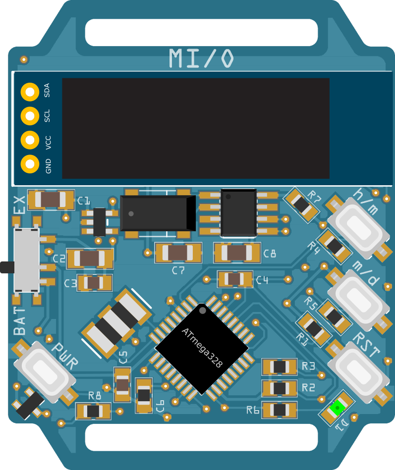
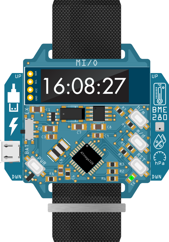
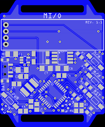
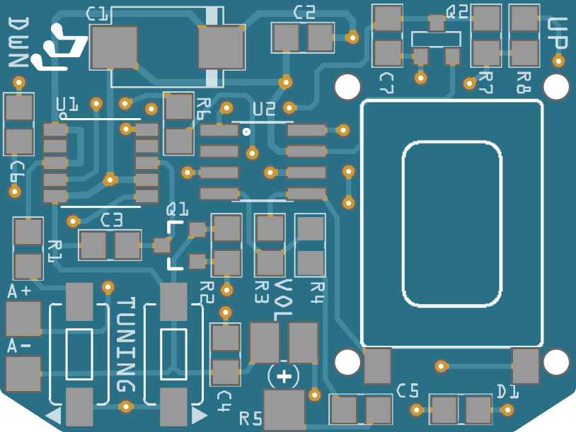
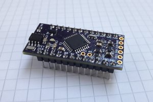
Top side:
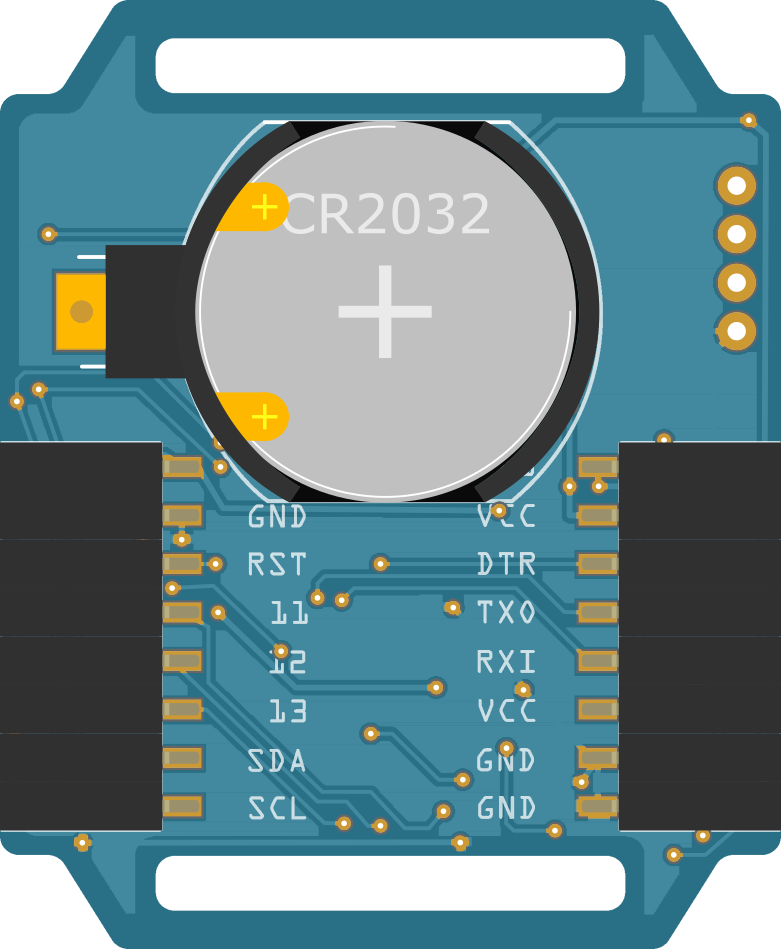
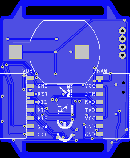
Bottom side:
- 40 x 50 mm
- Two cutouts for a wristband
- ATmega328 microcontroller, 8MHz
- Programmable via FTDI breakout or ISP using an Arduino Pro Mini as a programmer
- 128 x 32 I2C OLED
- PCF8523 Real-Time Clock (RTC) and calendar
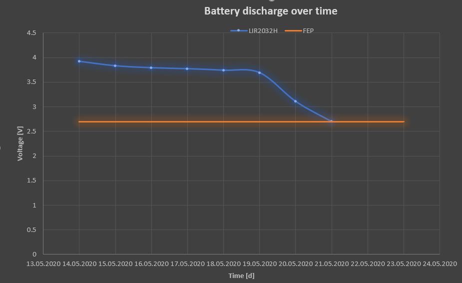
- Powered by a CR2032 coin cell or external power supply
- On-board LDO for external power supplies
- Latching style on-off, programmable automatic switch-off
- 2 x 8-holes SMD female headers on backside to access pins; can be also used to plug in add-on modules
Casio used some kinda add-on modules like a TV remote on their 90's wristwatches:
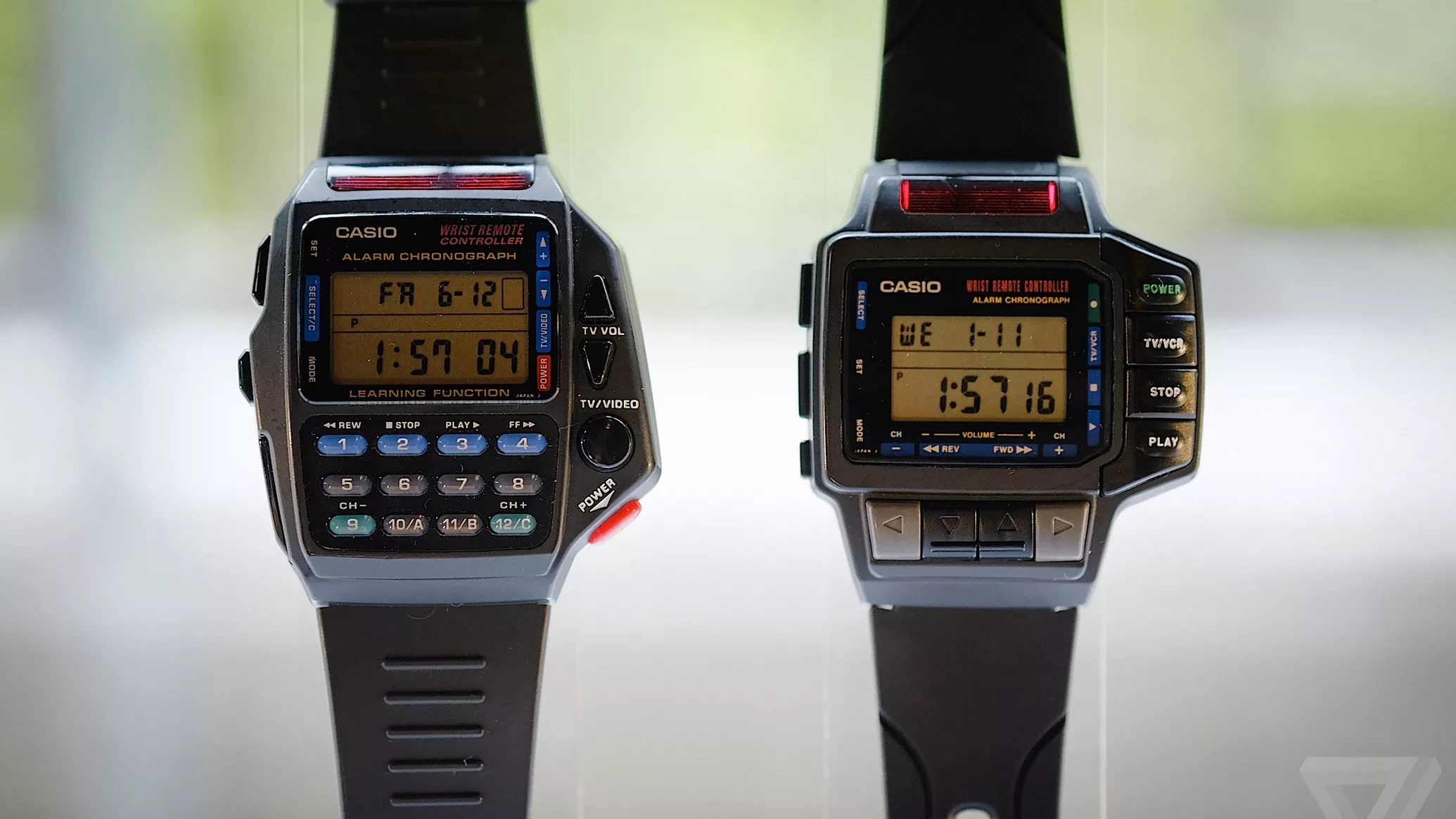
Image courtesy of theverge.com
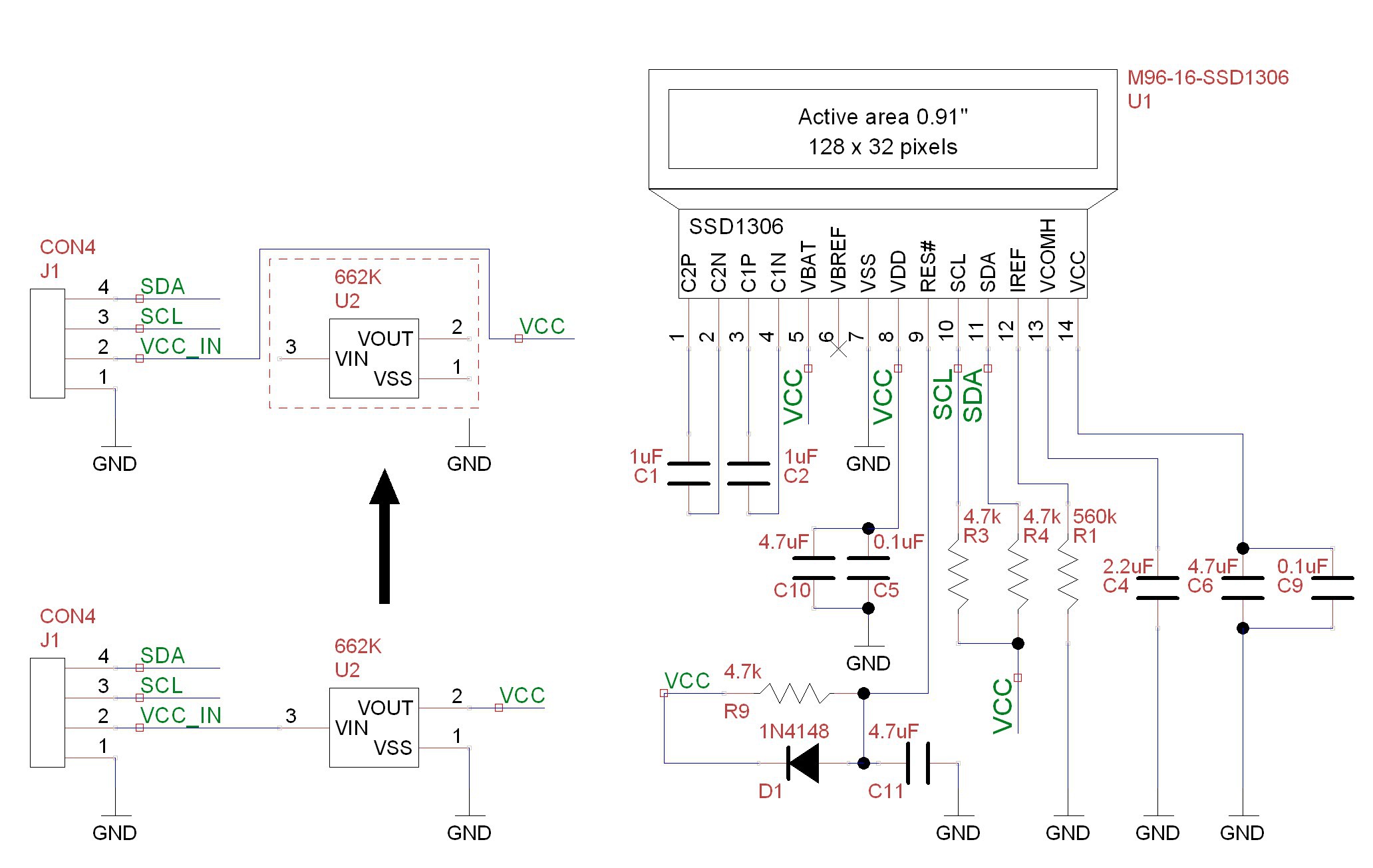
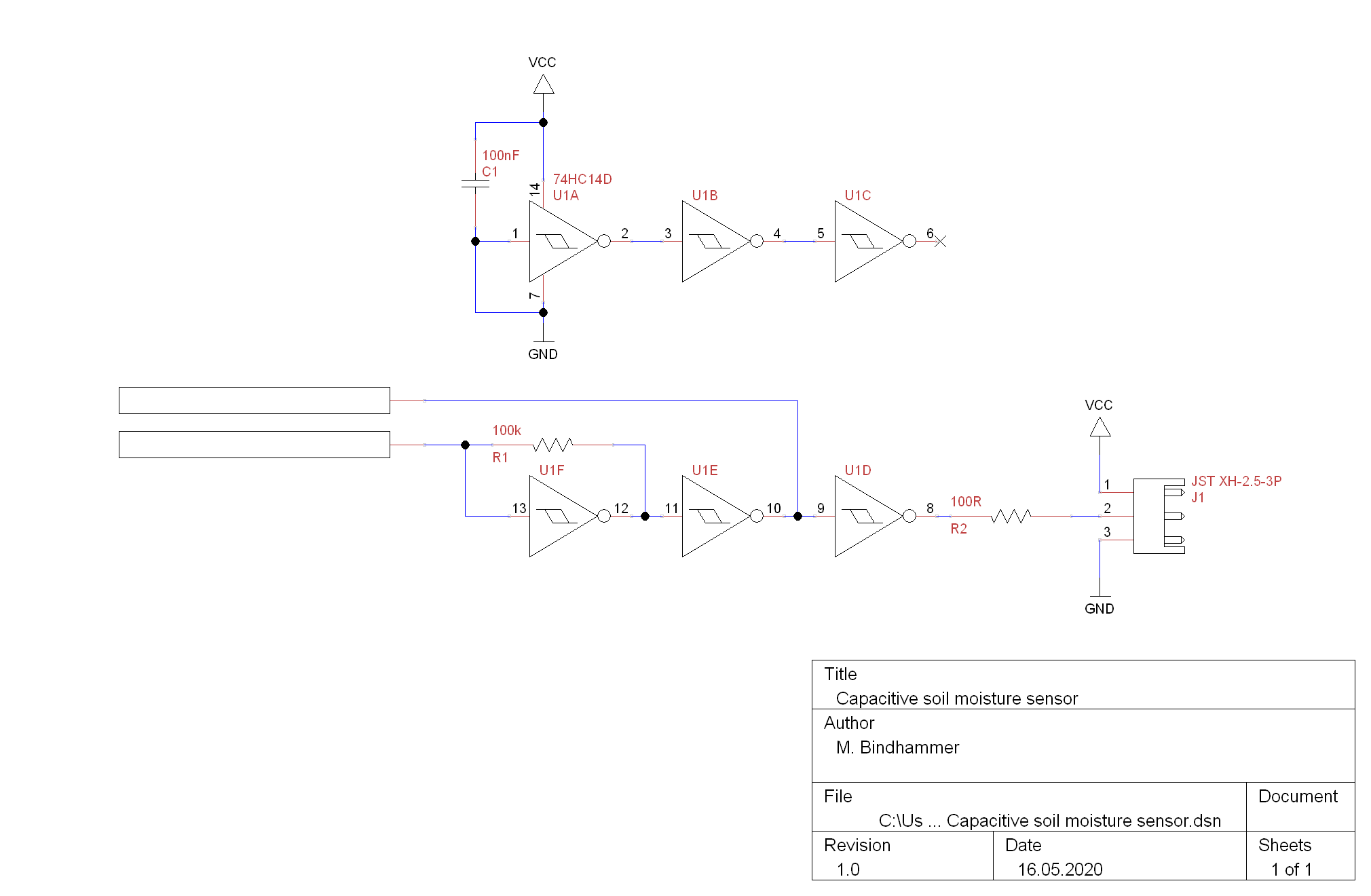
2. Schematic
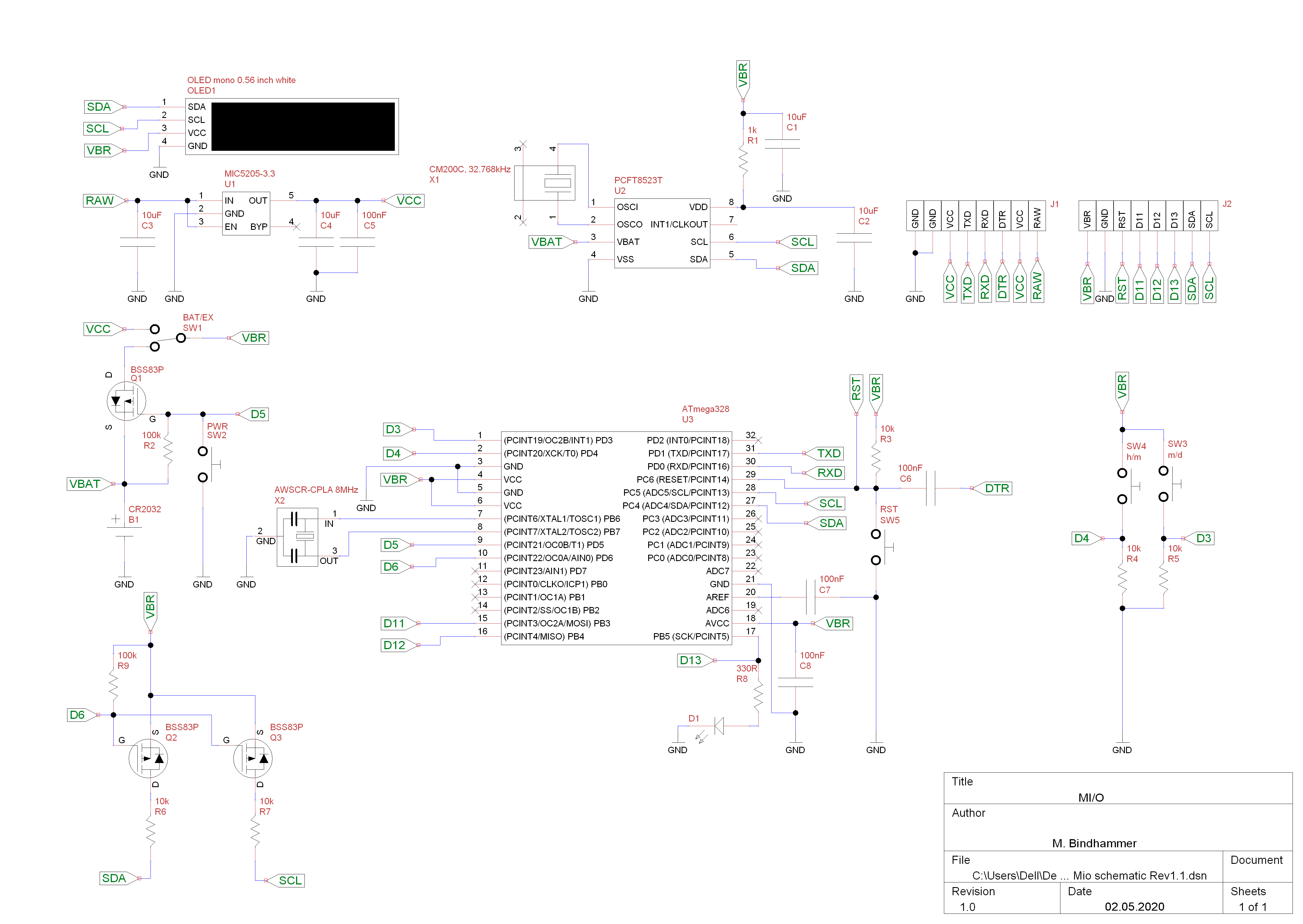
Unlike other watch designs where the microcontroller is put into sleep mode, MI/O completely switches off everything except the RTC when the watch is not in use.
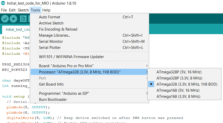
The disadvantage is that we cannot use a bootloader if the board is used as a wristwatch. With bootloader the ATmega328P needs about 2.1 seconds to boot. This is not acceptable in watch mode, because you would have to wait 2 seconds after pressing the PWR button and hold the button until the time is displayed. Fortunately we do not need a bootloader. We can program the chip directly via ISP. The time/date is then nearly shown without delay after power-up. And if we need a bootloader for other applications, we can of course burn it onto the chip.
Q1, R2 and SW2 form a simple latching style power circuit. On power up the R2 resistor pulls up the gate on the Q1 p-channel mosfet which prevents current from flowing through Q1. When the user presses SW2, the gate on Q1 gets pulled to ground which allows the current to flow, the ATmega328P turn on. It then drives the GPIO pin to ground. When the user releases SW2 the GPIO pin keeps the gate low. The ATmega328P then just Hi-Zs the GPIO pin when it needs to shutdown. This way it can make sure the data is safe when it shuts down. Q2 and Q3 enabling/disabling the I2C pullup resistors R6/R7 to avoid the devices are being "phantom powered" via the I2C lines themselves. However, phantom powering cannot be completely prevented as R2 connects the positive terminal of the battery with an I/O of the ATmega328P, and the ATmega328P powers itself through the internal protection diodes. R2, the microcontroller and maybe other peripherals acting as a voltage divider or resistors in series. The value of the resistor R2 should therefore be set as high as possible without putting the Q1 MOSFET gate into an undefined state. If we use a value of 1MΩ for R2, we should end up with a stand-by-current of around 4µA.
Two small modifications must be made to the breakout board of the OLED1. The LDO at the backside has to be removed and VCC_IN has to be connected to VCC by a small wire jumper, see redrawn schematic of the OLED breakout below. Instead of a wire jumper a SOT23 jumper could be used. This ensures that all components on the board have the same voltage level. The OLED1 works without LDO in a voltage range of 2-4V without problems. Furthermore the 4.7k pullup resistors R3 and R4 on the OLED breakout have to be removed to avoid mentioned "phantom powering".
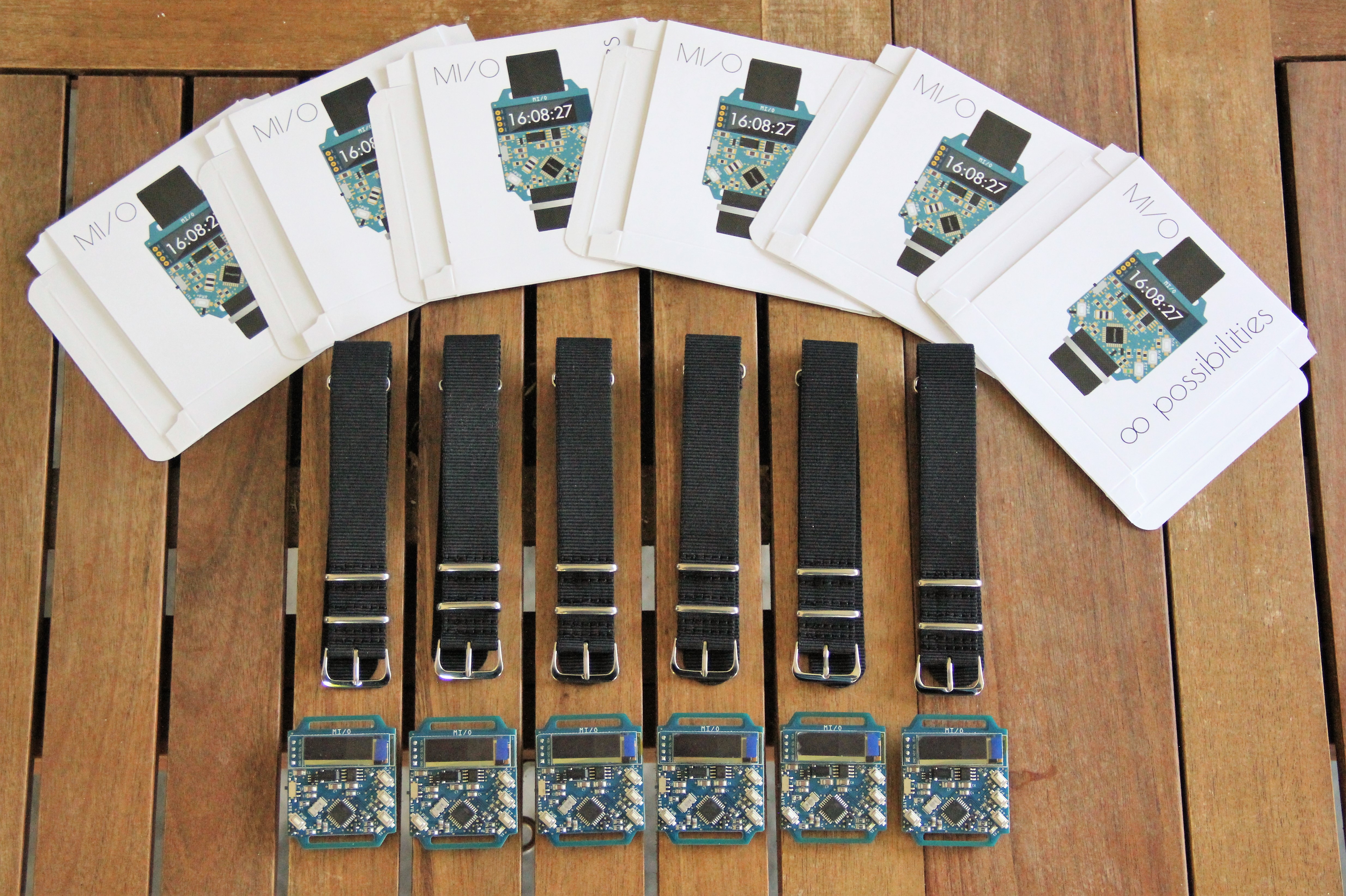
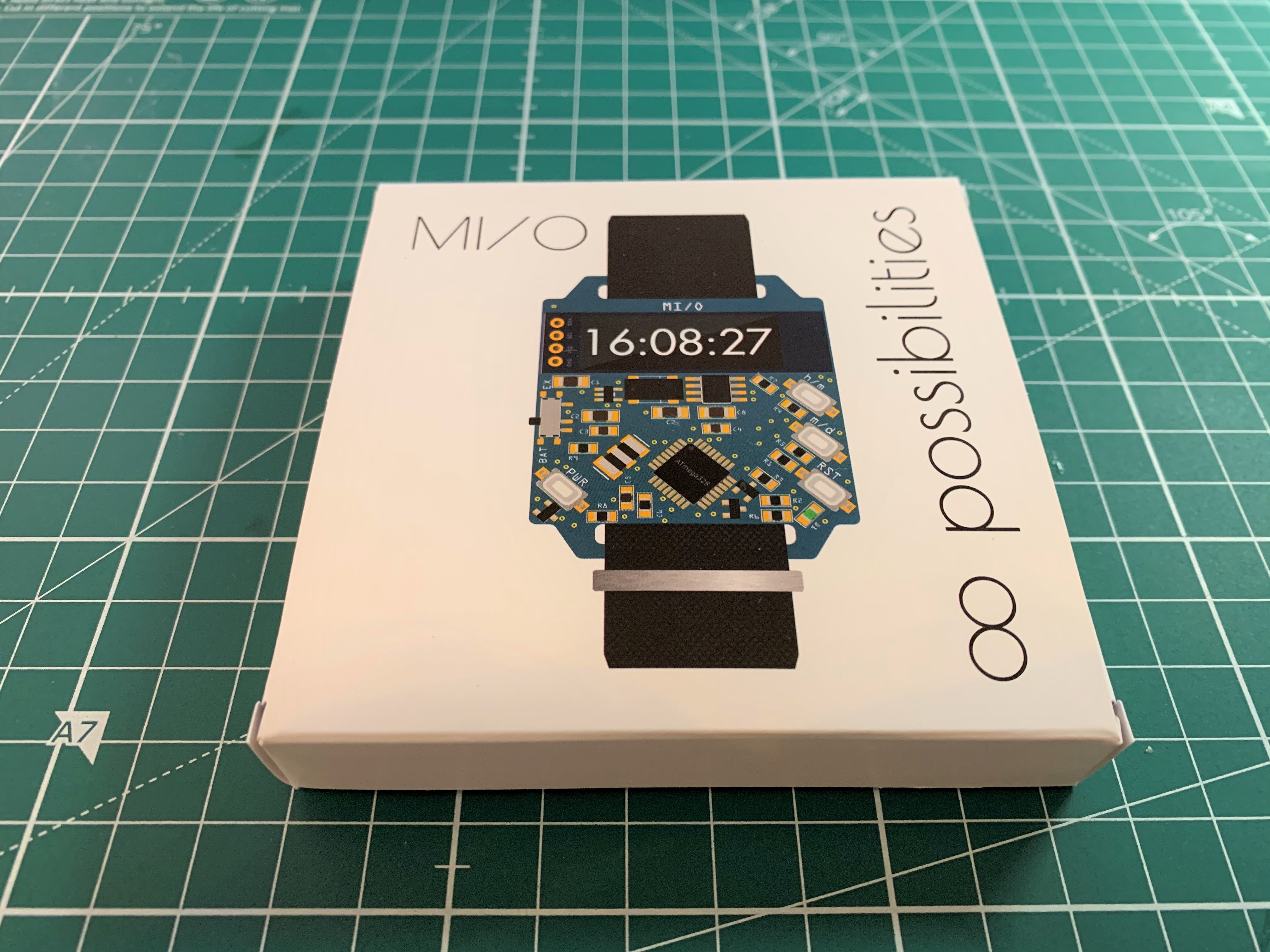
3. Prototype

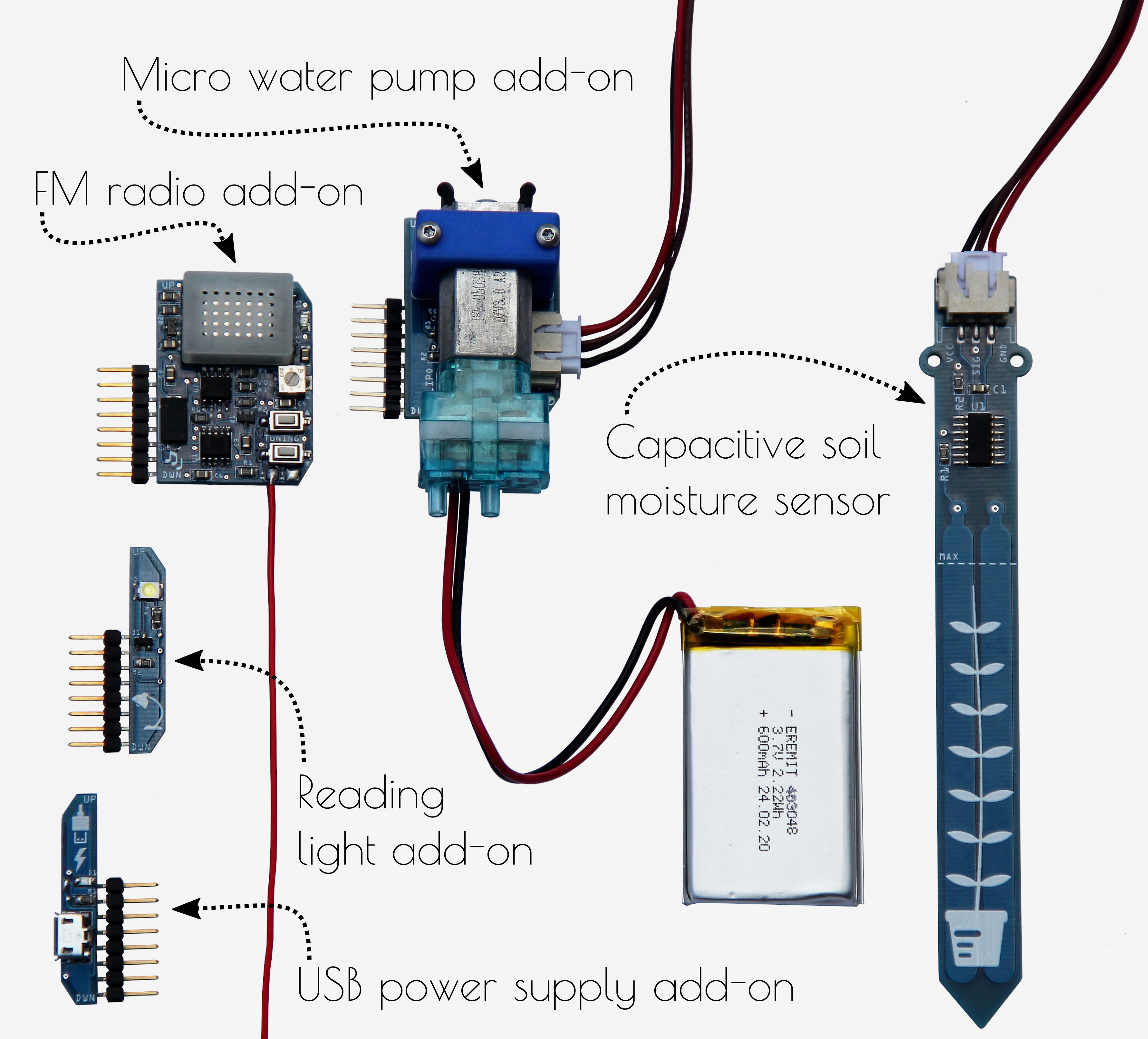
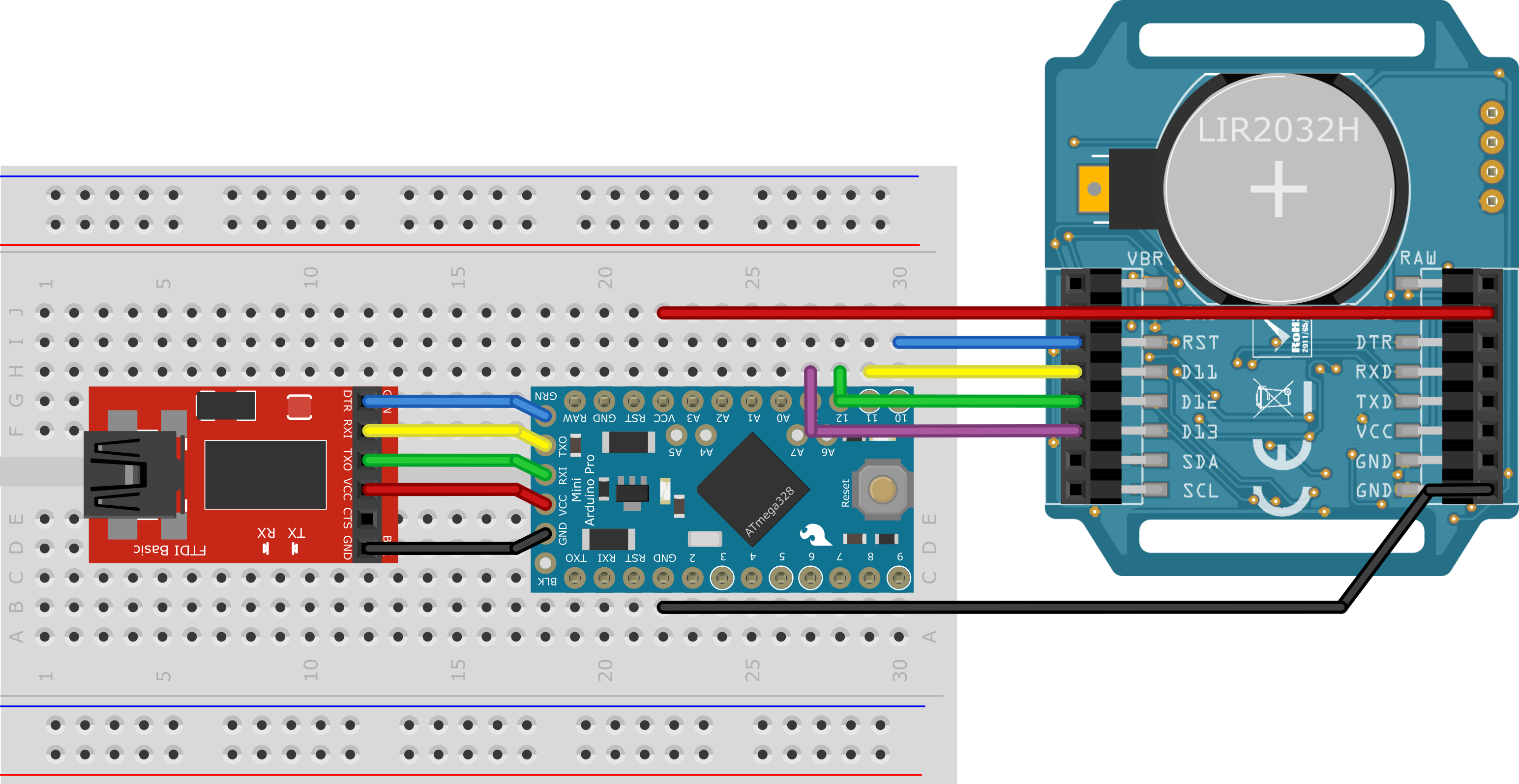
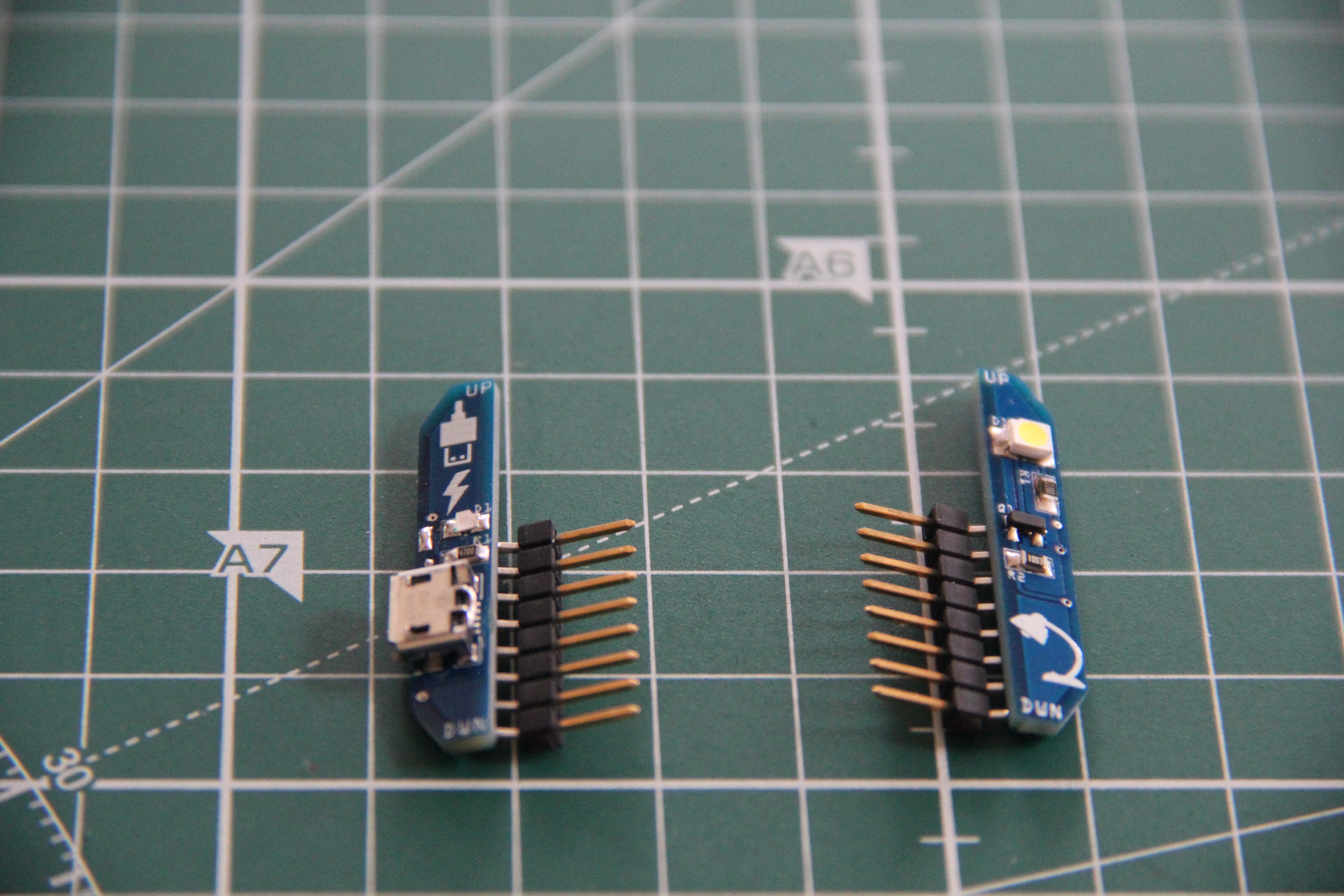
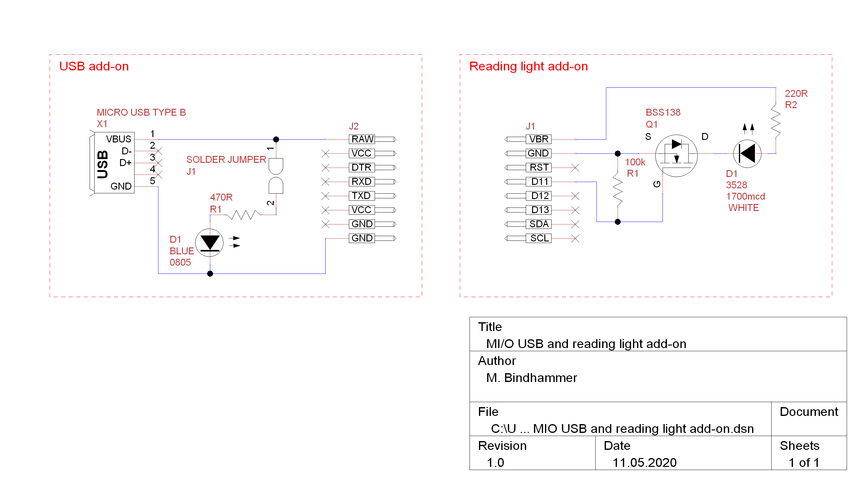
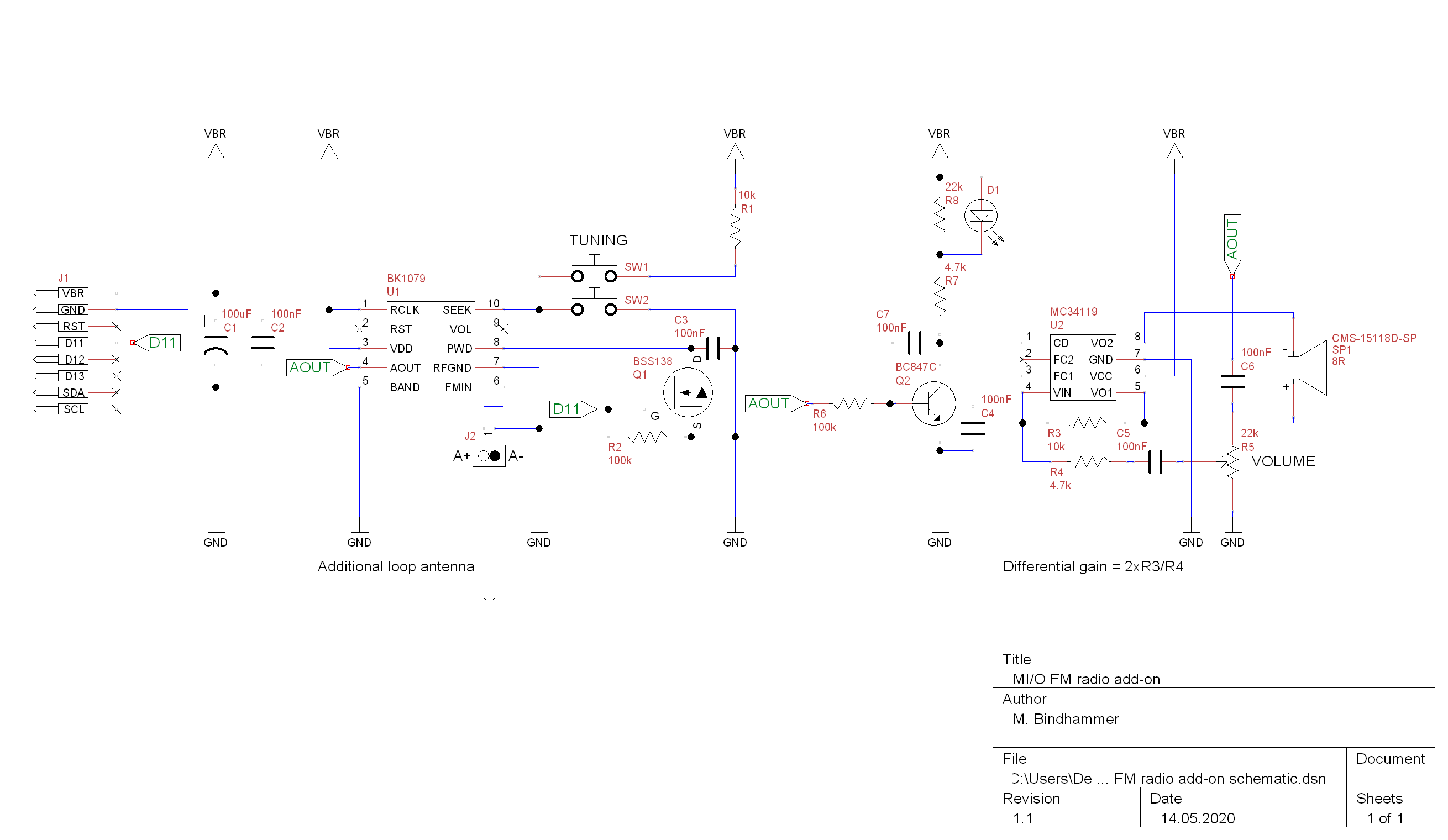
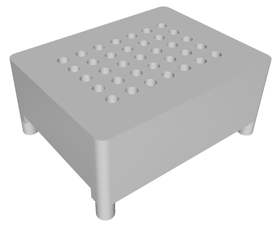
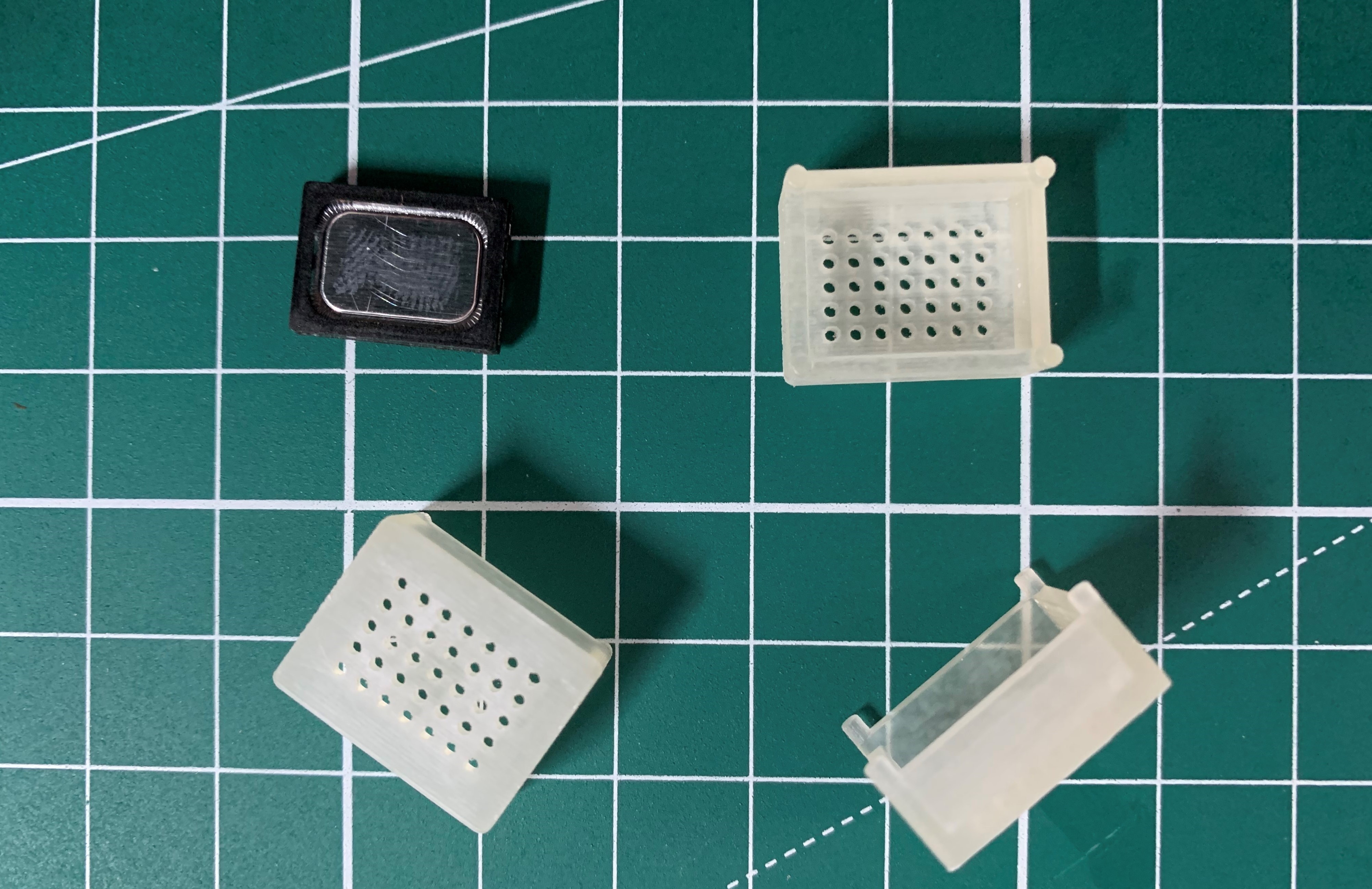
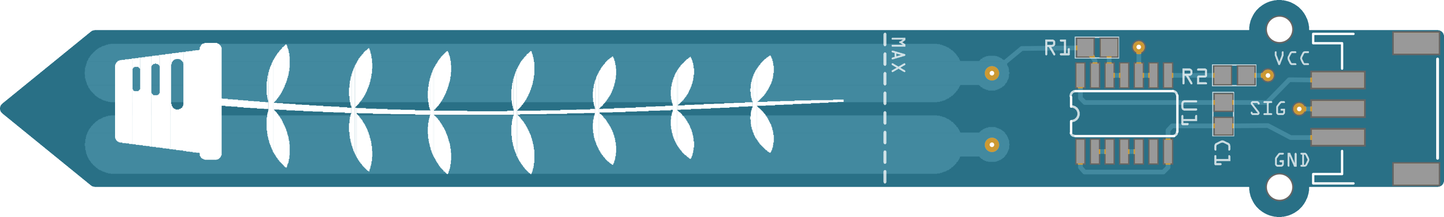
4. Add-on modules
Just two ideas for add-on modules: USB power supply and a BME280 humidity, pressure and temperature sensor. Want more ideas? Reading light, laser cannon, keyboard, ToF-sensor, TV remote control, accelerometer, compass... Endless possibilities.
So far built add-ons:
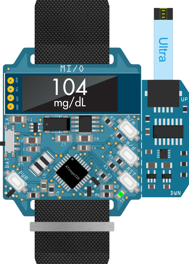
5. Future work
The watch itself is finished as far as the hardware is concerned and is in pre-production. However, there is still some work to be done on the software side. In the future I would like to develop more add-ons for MI/O. Next, a blood glucose meter is planned, based on my work here.
This project is released under the CC-By-NC license.

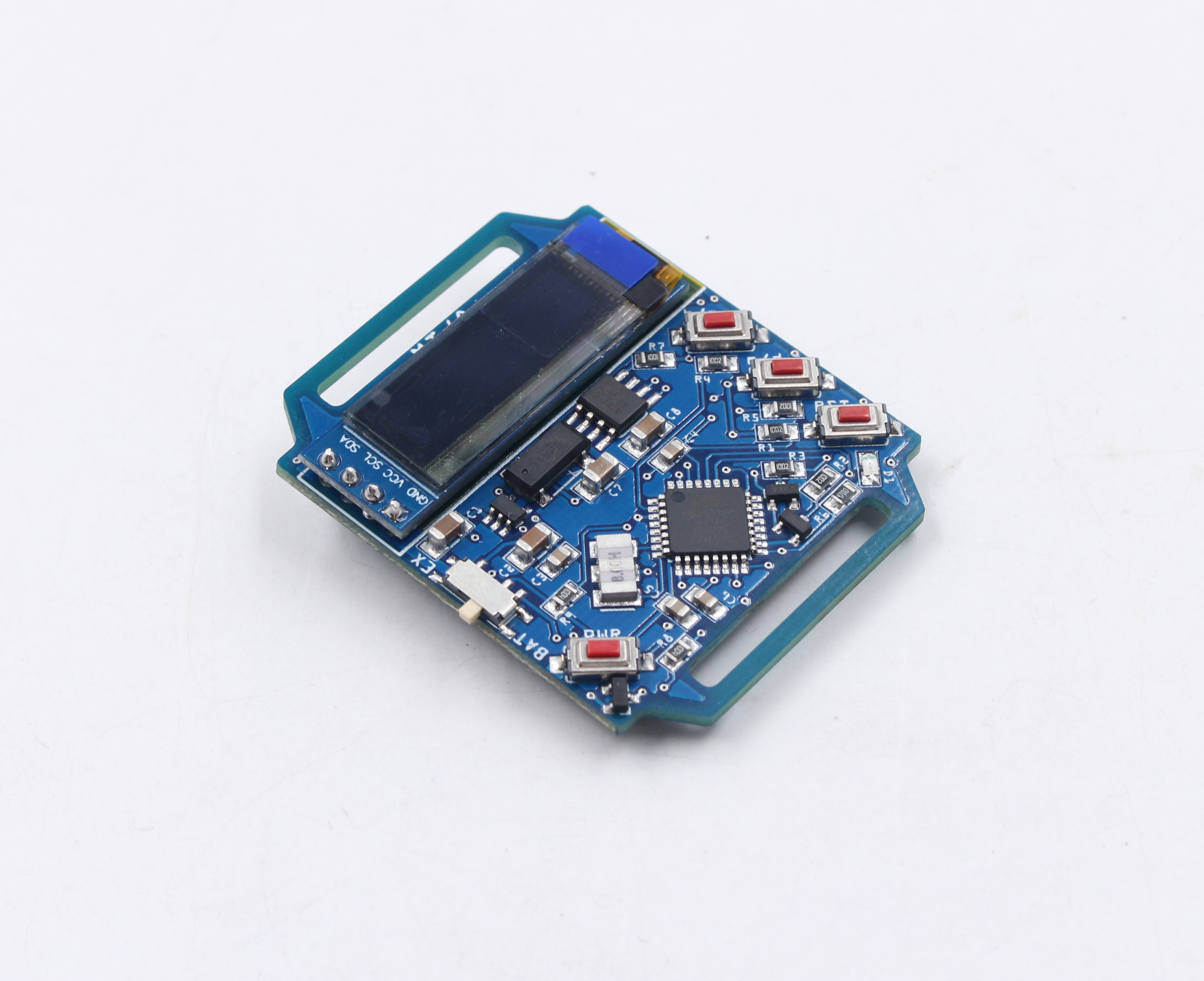
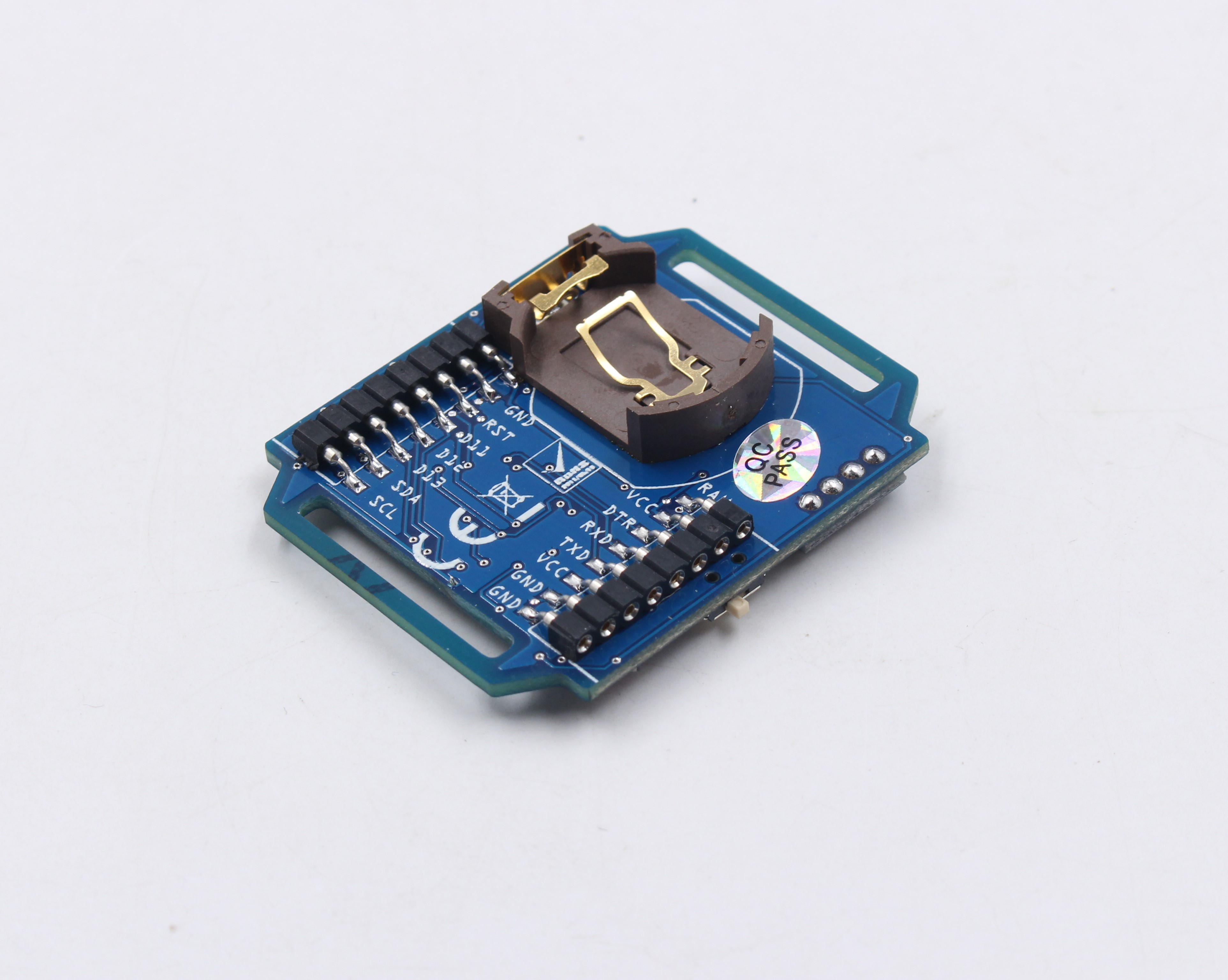
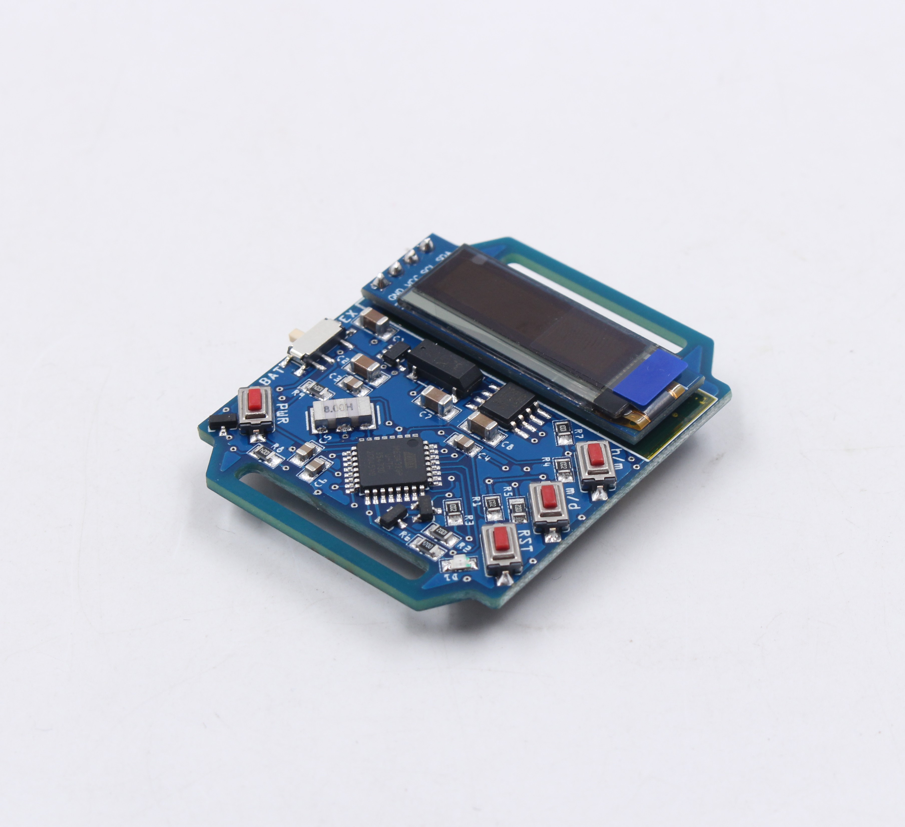
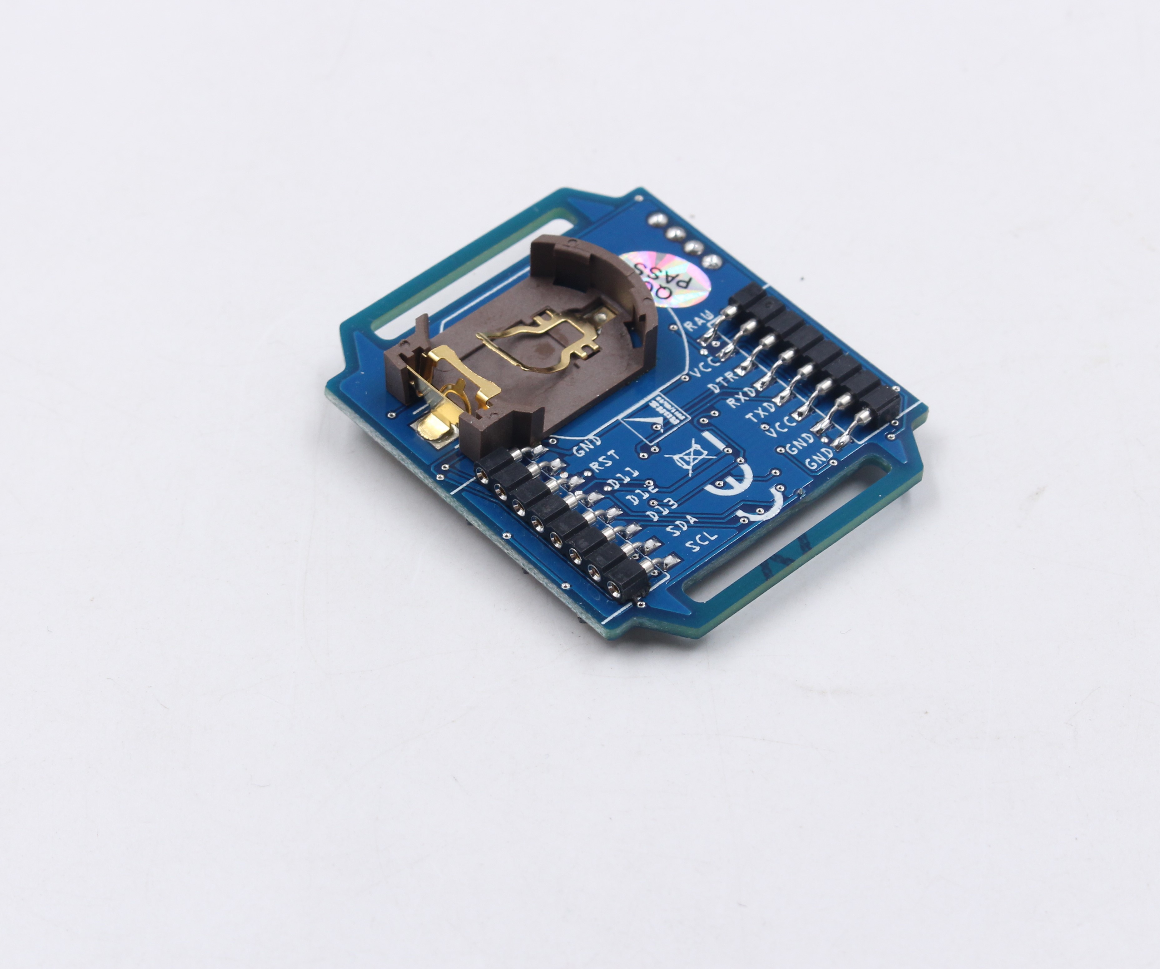
 As usual I used a stencil, low temperature melting soldering paste and a hot air gun to populate the board. Some soldering was done directly with a soldering iron. I am very satisfied with the result, looks like machine made:
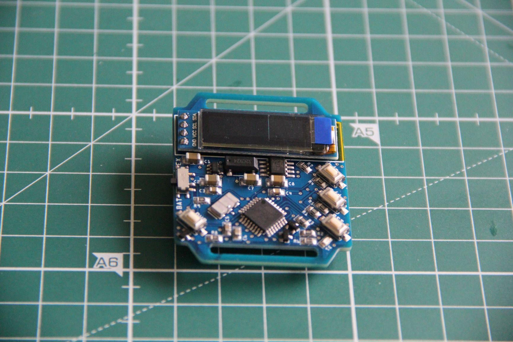
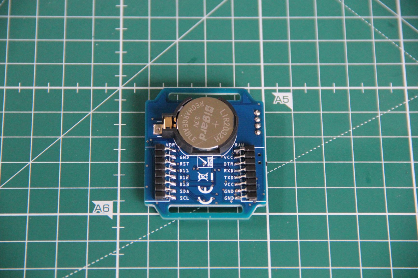


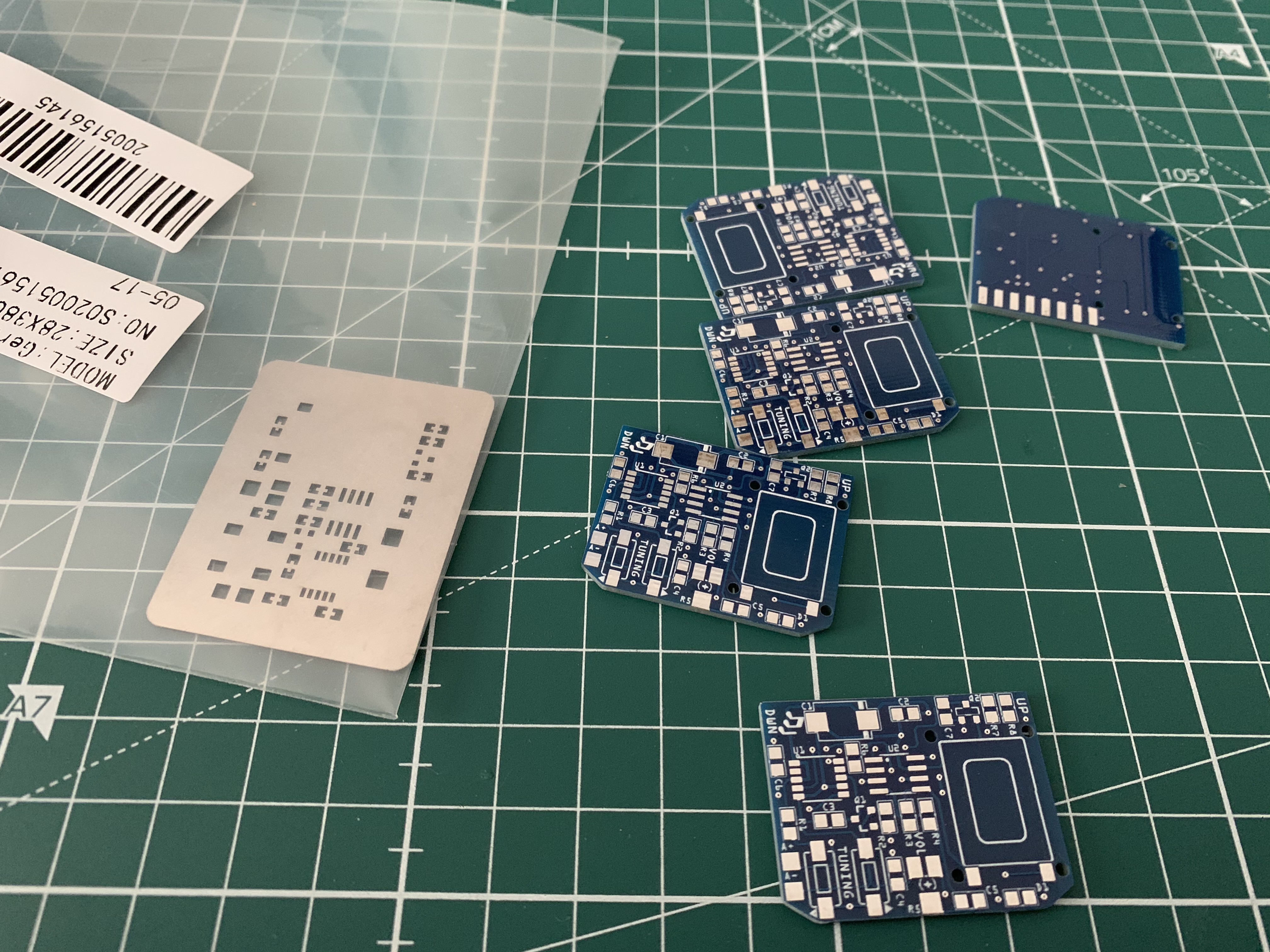
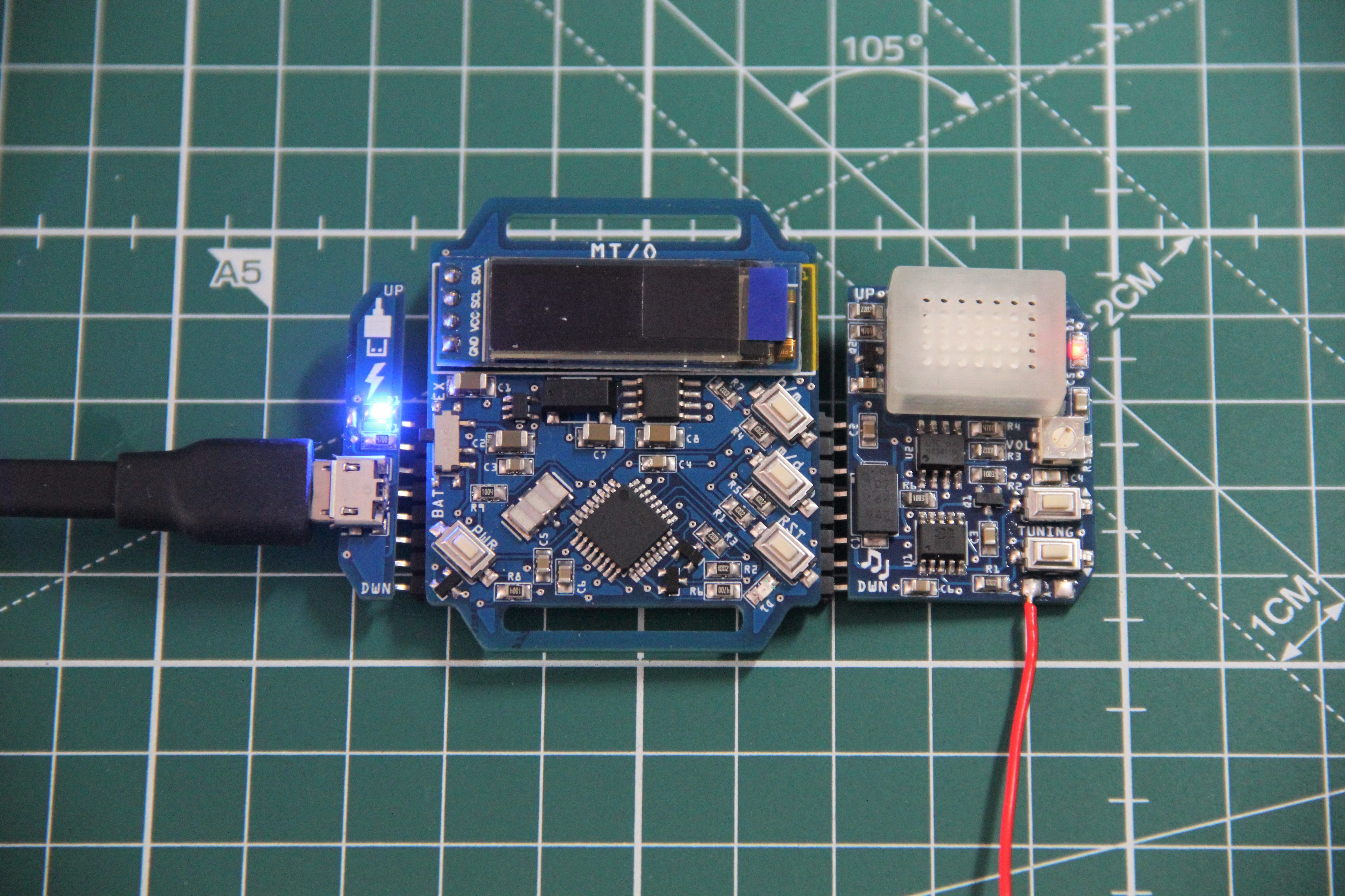
 Populated PCB:
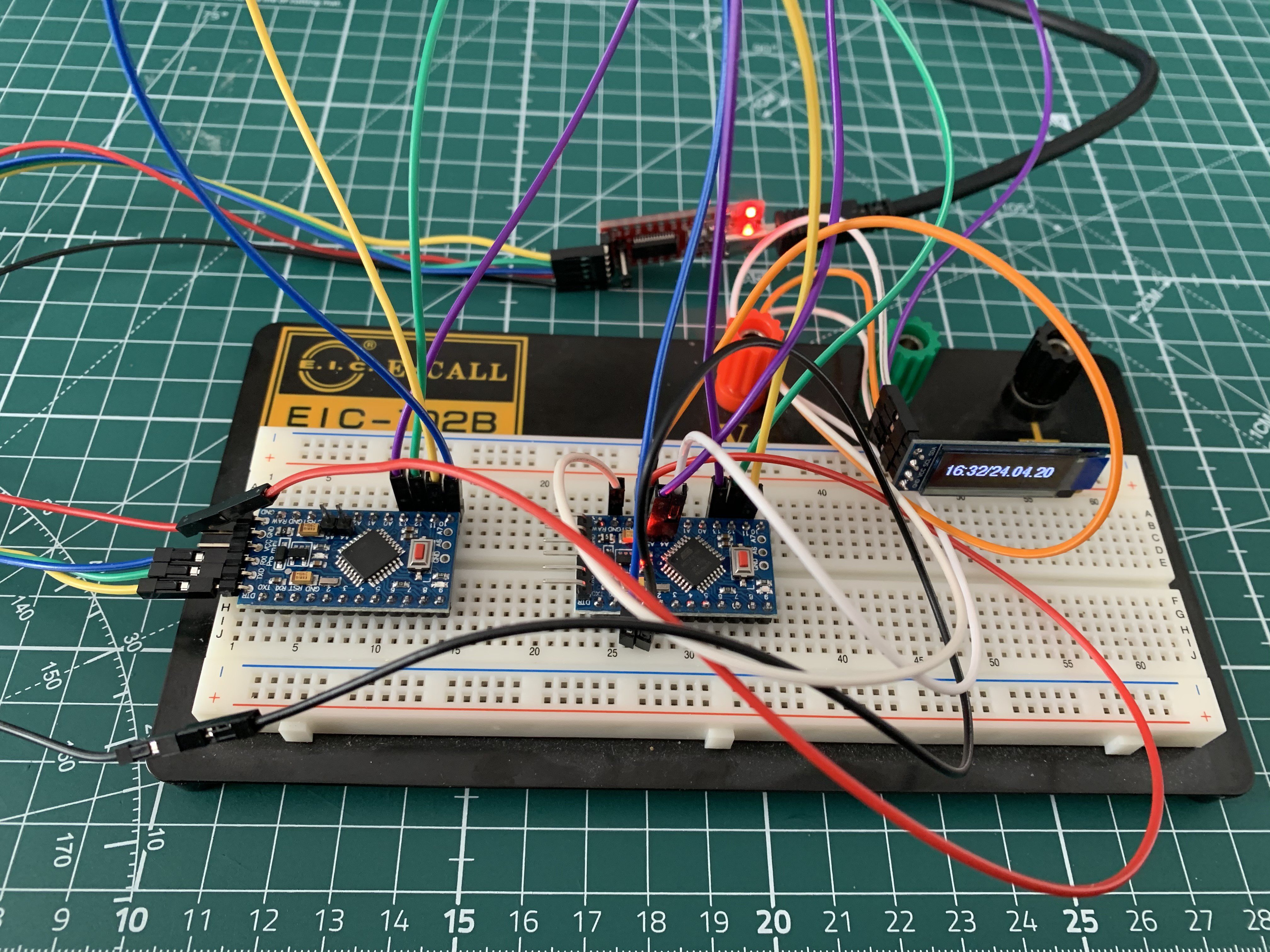
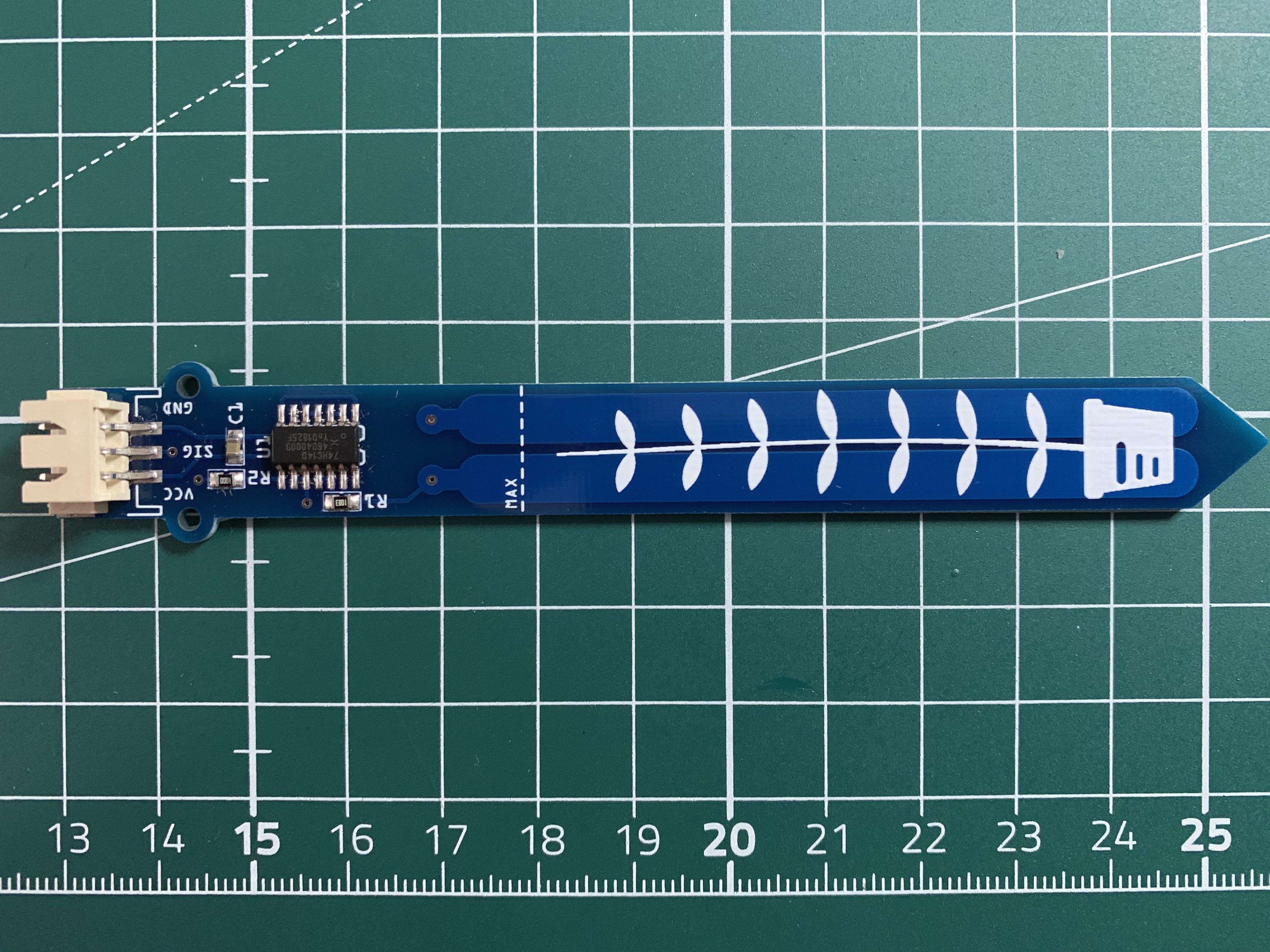 Test code...
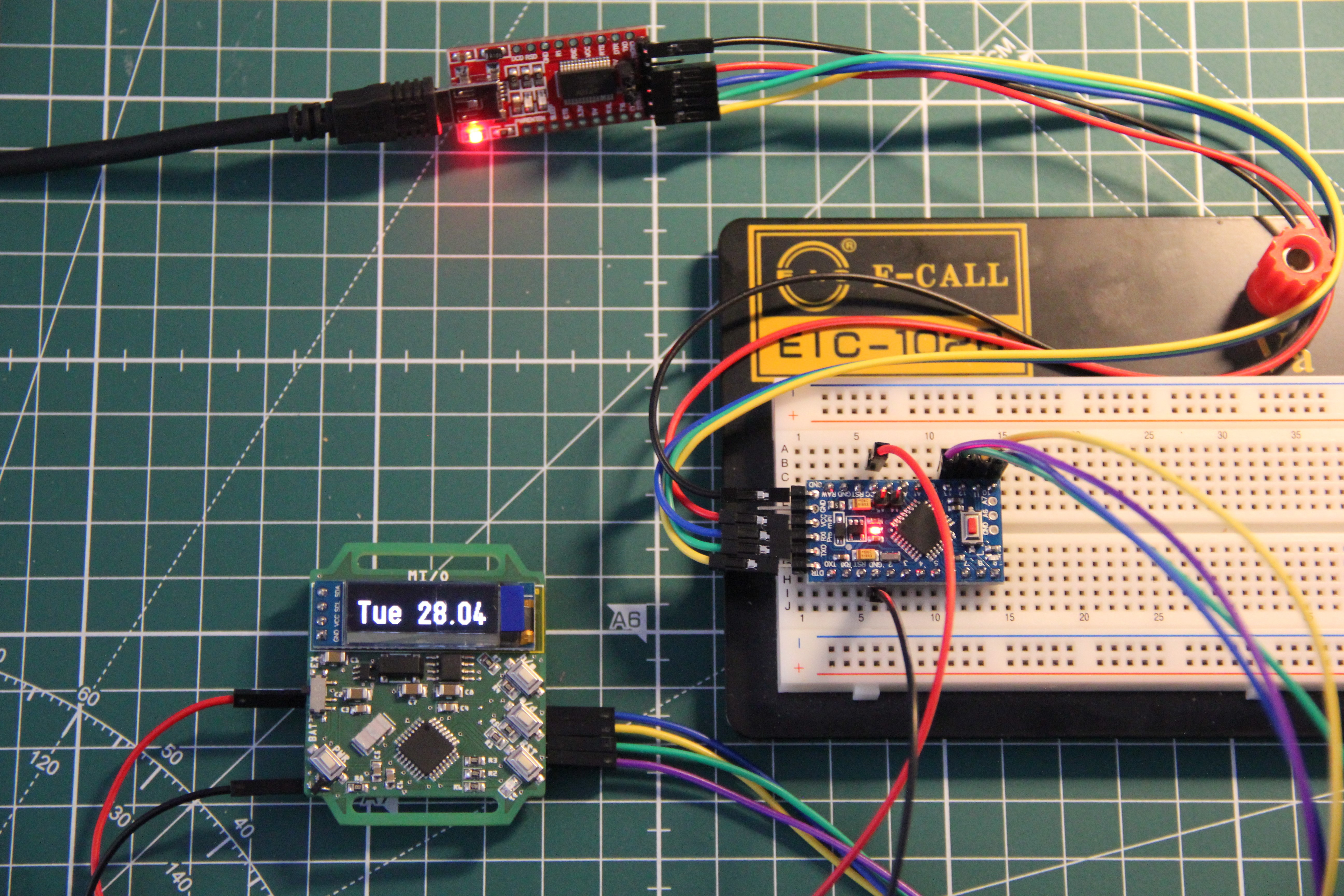


 Taiwo
Taiwo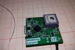
 Max.K
Max.K
 ElectroBoy
If you are still looking for testers, I would like to apply!