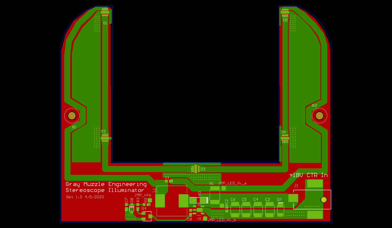
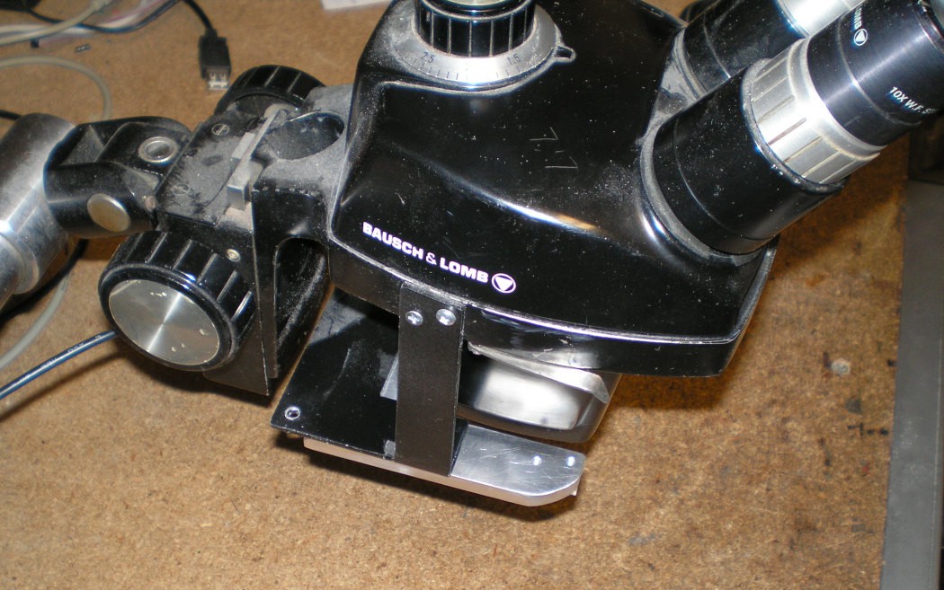
The first iteration of this illuminator had all the parts on a single PCB which would straddle the lens of the microscope. The physical size was set by the microscope.
 First Iteration Re-Design
The completed design was on a 2 layer board. Fabrication costs for the board alone were a little over $80US. This exceeded my interest in the project, so I re-designed it with an aluminum plate to serve as a mount and heat sink. There are 4 small PCBs with an LED and two mounting holes on them and one larger PCB with an LED in the center and the power supply on it. It made sense to me to put the small boards on a panel with the power supply board, and cut it up before building it. The cost reduced version PCB costs were about $20US, which is a lot more acceptable.
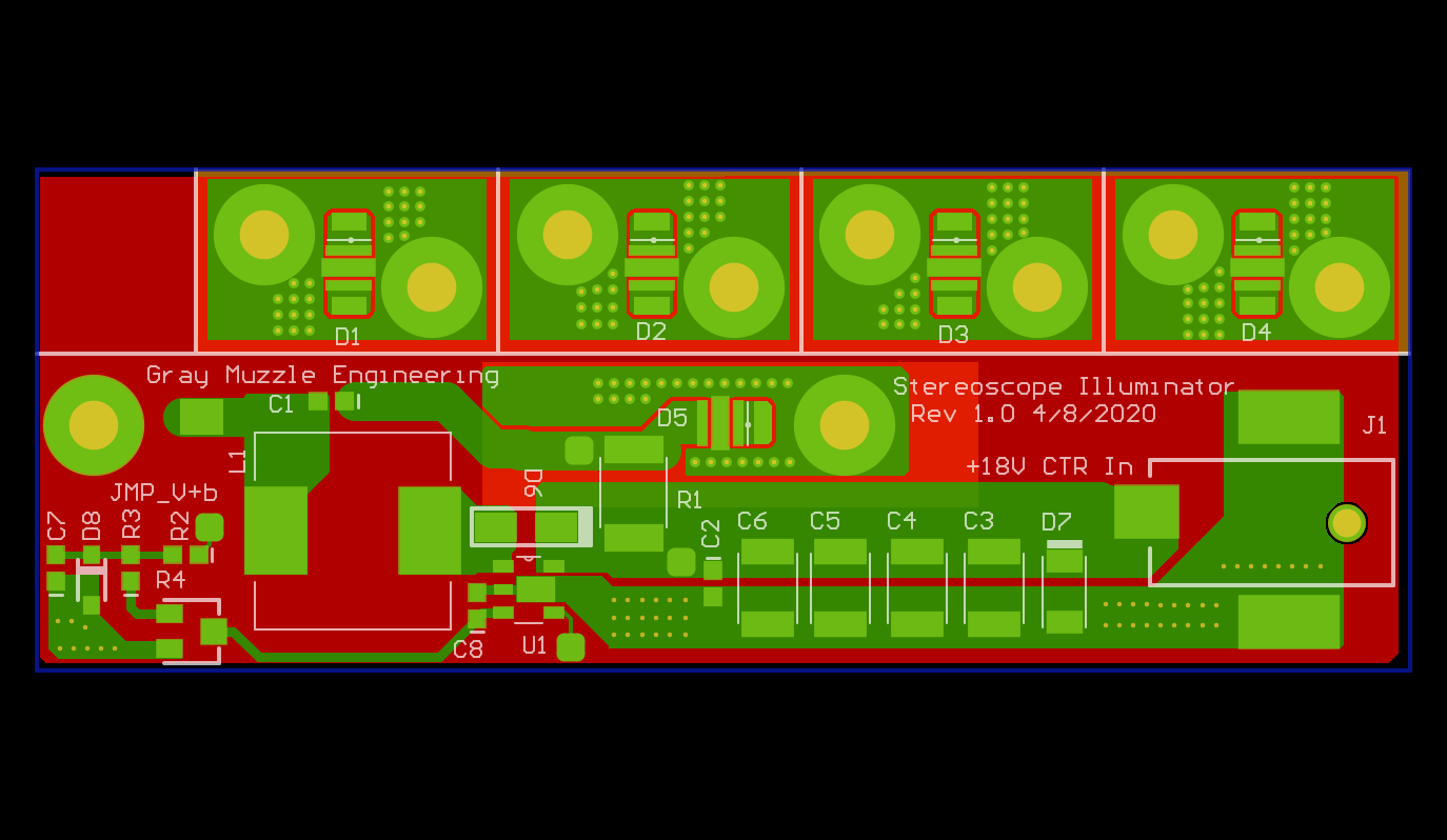
The white silkscreen lines for cutting the board up are visible on the board layout shown. Cutting the board was done with a vertical band saw. I thought about assembling the board before cutting it up, but was concerned that the board would flex too much while cutting and damage the boards or components.
The heat sink/mounting plate can be seen here:
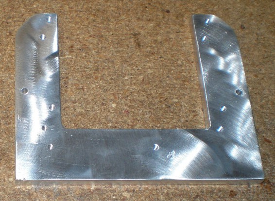
It is fabricated from 1/4" aluminum, with mounting holes for the LED boards and main board tapped for machine screws. The heat sink outline was rough cut with a vertical bandsaw and then cleaned up and the holes drilled on a mill. Tapping was done by hand on the work bench.
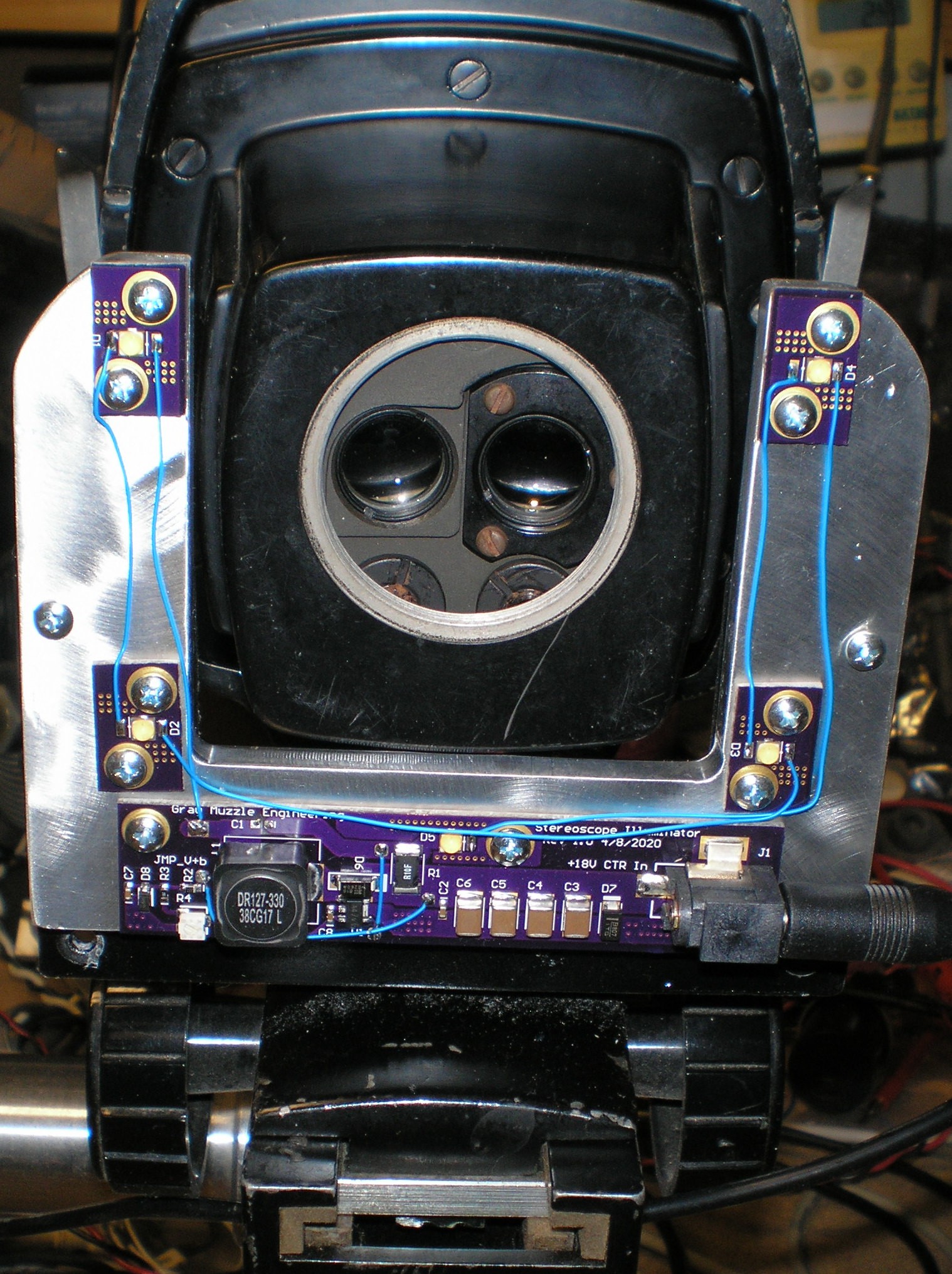
The assembled illuminator looks like this:
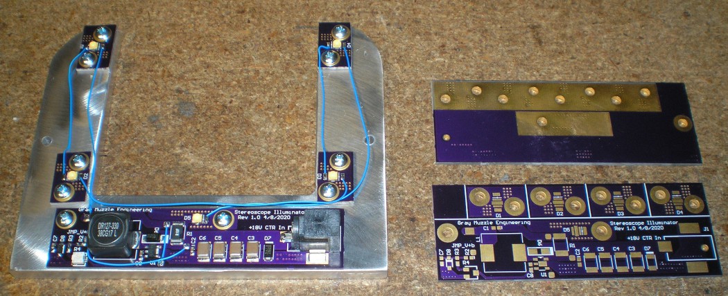
I included the bare boards to show how the unfinished boards look. Soldermask near the LEDs on the back side of the PCB is masked to give better heat transfer to the heat sink. The entire back side of the PCB is a ground layer in addition to the heat sink. The blue LED wires will be glued down to the heat sink to prevent snagging them on stuff in use.
The LEDs have a heat sink pad that runs through the middle of the package that does not have an electrical connection. This pad was tied to the ground plane. Clusters of vias can be seen around the LEDs to conduct the heat from the top of the PCB to the back side. Osram OSLON Square 3000K LEDs were used. They are capable of handling up to 1800mA, but initial tests look like under 50mA will suffice. At 250mA, this thing would give you a sun tan.
The power supply design is just a re-use of the design used previously on the goose-neck microscope illuminator shown in a previous project. Because the back side of the PCB is a solid ground sheet and needed to be flat for good contact to the heat sink, I included two jumpers in the initial design rather than going to a 4 layer PCB.
Here is the first LED illuminator that I built back in 2013.
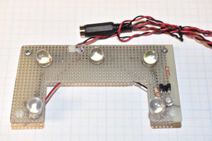
It uses a simple linear constant current regulator. It was designed on a napkin, and worked well enough to use for 7 years. Because it was built on perf board it needed to sit on standoffs, 1/4" below the plane of the mount plate. The large LEDs stuck farther down into the work area under the microscope lense.
 Bharbour


 slisgrinder
 sky-guided
 Chris Hamilton
1800mA! that's insane. I though that was a mistake, so I checked the datasheet. And it's indeed 1800mA. You'd need some serious heatsinking when they are running at 5W each.
Clever idea to create separate panels. No need to waste FR4 when you already have an aluminum backplate.