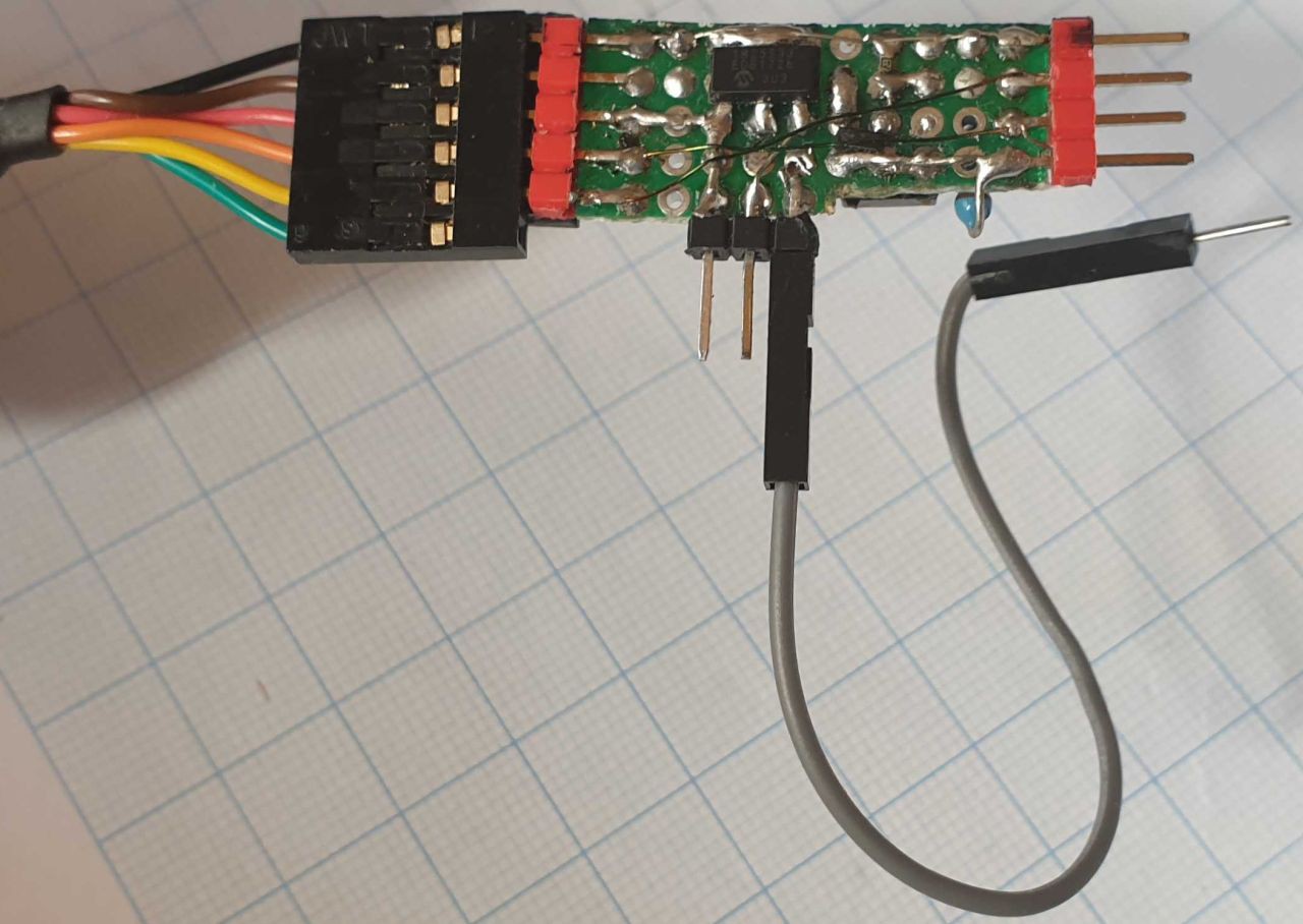
This device is something that a random MCU hacker could assemble from parts lying around, so find suitable parts, find their pinouts (regulator, FET, UART) and plan how they shall be placed on the PCB.
- I recommend dedicating one edge to ground, to keep it clear which end is ground.
- RX/TX traces according to the UART, I used an FTDI cable but use what you have.
- I included both female and male headers for UART; male for home/office use, where I have FTDI cables around, and female for PCB UARTS in my EDC (EveryDay Carry) box.
- Convenient to have the target end just 4 holes wide to allow it fit tight places (my through hole LED resistor is already PITA)
- GPIO zero could be the fifth pin in the row, but then the header wouldn't fit Sonoff Basic style four hole layout (sure could have an adapter for that)
- Many USB UART cards/cables do provide also 3.3 Volts, but their regulators may not be up to the task of flashing ESP chips, and nobody wants "almost perfectly" flashed devices. If you know your UART has beefy enough 3V3, and only use that, you'll probably be fine without the LDO.
- This MCP1825S LDO (Low DropOut) regulator has a convenient in-gnd-out layout, AMS1117 (which your target device very likely contains, it's cheap) is slightly more awkward. I don't like the power hungry AMS1117 but in this kind of application bad efficiency wouldn't really matter.
- Most LDOs don't mind their input and output being shorted as they don't sink too high output, but just be happy that it's high enough. This was used to add 5V output option; adding a jumper to two of the header pins will change output to 5V, should something require that (most devices don't). I'd suggest investigating and testing if your LDO allows shorting In & Out.
- LED I originally didn't have but never remembered which button was which, the LED clearly shows it. And warns there's power on, preferably power down before attaching target device
For firmware and flashing software there are various options; for "production" devices I have been using Tasmota firmware and Tasmota-PyFlasher or Tasmotizer for flashing, but also ESPurna, ESPHome, ESPEasy, Homie (and others I forgot or haven't heard about) have their strengths, check some comparisons to find out the one (or two) for you. For ultimate flexibilit you can of course write your code, there a framework library like ESPHomeLib might help concentrating on getting the task done.
As I'm most familiar with Tasmota and that I have flashed in all the devices mentioned, I'm including device templates for Tasmota.
2
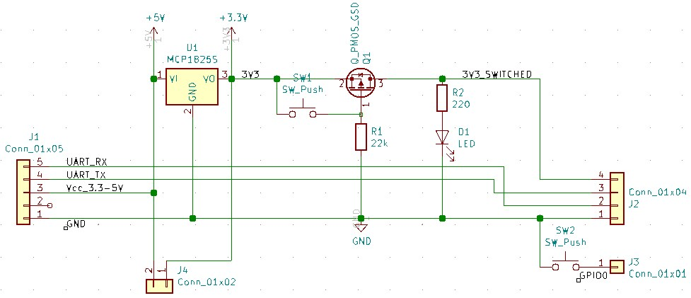
Schematics, assembly instructions etc
For now the schematics:
3
Flashing BlitzWolf BW-SHP6 15A / Pro
WARNING! As of autumn 2023 the new hardware version is internally completely different and doesn't have an ESP but something called "W701" that will probably be supported by OpenBeken at some point but currenty (Oct 2023) not. The W701 (apparently RTL8720) is placed on a PCB module which has the electricity monitor chip BL0937 on the other side so it's apparently not a common Tuya module which could have an ESP drop-in replacement.
These instructions for the older ESP82xx version.
BlitzWolf BW-SHP6 Pro (15A version of the original 10A SHP6) is an excellent WiFi switch with power measurement. I don't much care about the switch functionality but current monitoring is extremely useful in home automation - to notify, when a washing machine is ready, alert if fridges are working abnormally (like if someone needed the cellar freezer's socket "temporarily" for something else, which has happened), to record washing machine power usage cycle to figure out when would be the best time to run them with solar power, to monitor when a pump somewhere in your cellar runs, to have feedback, if a device switched on really runs..). The 15A version BTW has more accurate current, at least on low currents; with no current the 10A one shows a wildly varying 0 - 6 Watts sawtooth, but the 15A measures rather stable 0 W, with random spikes of 1W.
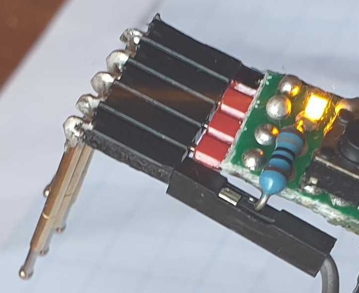
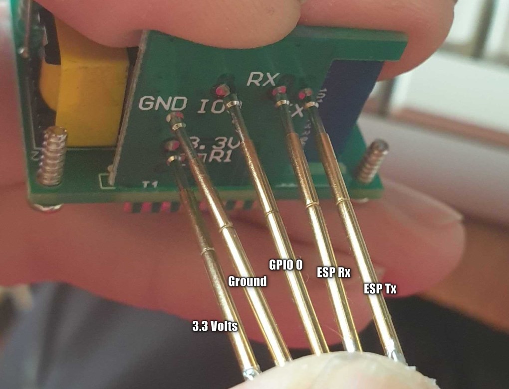
Anyway, the 10A version basically required a printed jig for flashing, but in this 15A version the pads are inconveniently close together for a printed jig, sure it's possible, but saw another way not requiring tedious slow speed printing:
Just five pogo pins soldered to a female header, whose pins are bent against the pogos to support them. Easily available parts (just be sure to get pointed pogos, not crown), easy assembly, makes a tiny adapter fitting any EDC electronics box, quick and easy to use. This works fine, but the 3D printed ones (a good looking one I saw in Thingiverse) may be more convenient for those who need to flash lots of sockets (I got less than a dozen), and those who totally shouldn't be disassembling mains powered equipment.
Timed flashing of five such devices in boxes - the whole process of "opening box-unscrewing-removing the transparent piece-removing the pink foam if needed-connecting flasher-flashing-putting back the pink foam if removed-putting back the transparent piece-turning the screw back" took 75-90 seconds per device (mostly depending on in which position the screw happened to be, when screwing back), of which the actual flashing (Tasmota 8.3.1) took 54-55 seconds.
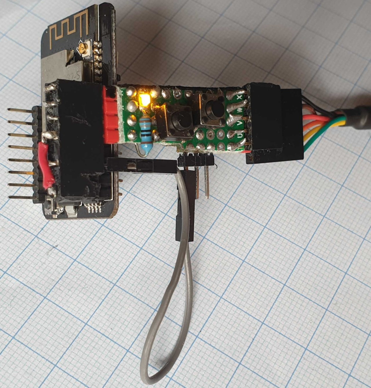
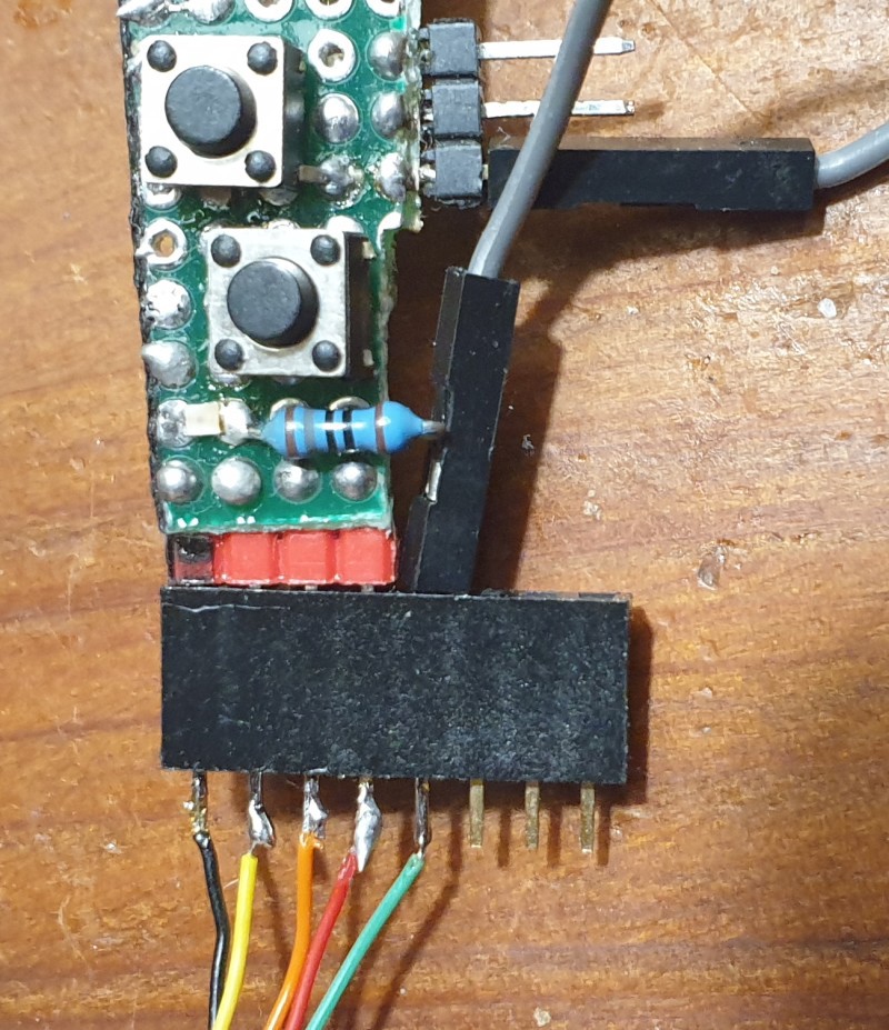
The adapter attached to the Universal ESP Flasher:
(The through hole resistor doesn't connect to the dupont wire, even if looks that way)
And, how to flash:
1. Open the SHP6: there's a screw hidden in a hole at the prong side - unscrew that and pull off the transparent top.
2. Remove the pink piece of foam, if covering some of the six pads, preferably don't lose it.
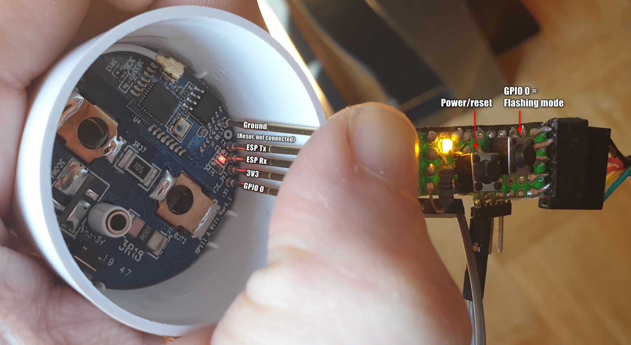
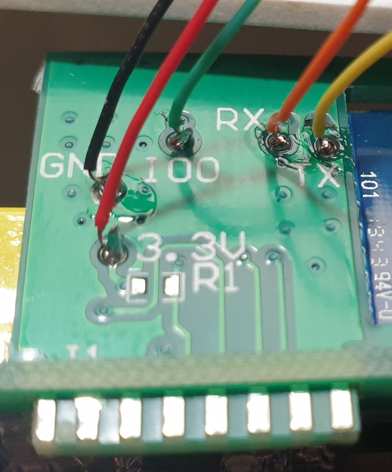
3. As below, but with UART first disconnected, point pogos at the pads, one by one, starting from one end. The first one might seem awkward but the third will take maybe ten seconds.
4. When UART connected, flashing software waiting for a keypress and pins aligned, with the free hand first press down the power button next to the LED, then the other button (GPIO zero), then release the first, last release the other button. We should be in the flashing mode now.
5. Start the flasher. If doesn't start, try #4 again. If still not after a couple of #4, continue with standard troubleshooting procedures.
6. When done, remove the flasher, find the pink foam (hiding in the pile of dupont wires probably), put it back, put the transparent case back, screw the screw fully in (in this phase the screw has probably twisted 90 degrees, use the screwdriver to position it correctly), plug to wall to see if the chosen firmware acts as expected.
Tasmota template for this model, blue light for switch status: {"NAME":"Blitzwolf SHP6 15A","GPIO":[158,255,56,255,132,134,0,0,131,17,0,21,0],"FLAG":0,"BASE":45}
4
Flashing ESP32-CAM
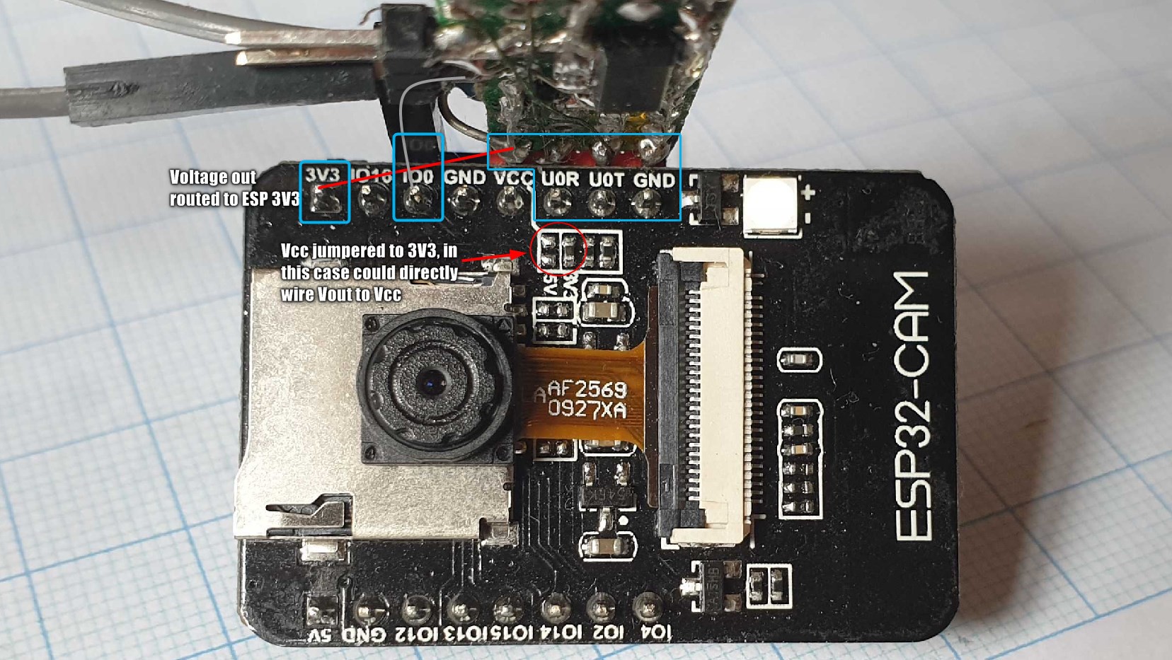
The ESP32-CAM is an amazing deal - an ESP32 with a camera module, SD card reader, 3V3 regulator, external antenna connector, power LED for $7?!?
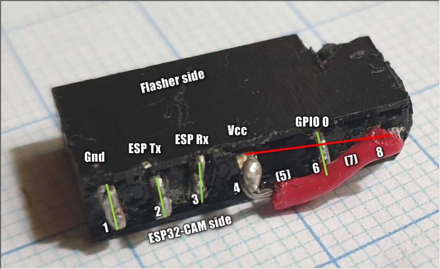
The only major caveat is that it requires an external UART for programming, and the normal keep-GPIO0-grounded-while-connecting-power-to-get-to-flashing-mode-and-remove-grounding-for-normal-running. Not that hard really but I hate bad usability. So, here's the Universal ESP Flasher adapter for ESP32-CAM in all the glory:
Yep, it's a piece of double row female header block, one end slightly mutilated, a piece of red wire added. Just what we need.
Pins of first, second, third and sixth rows are bent and soldered together, pins of fifth and seventh row removed and fourth pin from one side is routed to eighth=last pin of the other side with RED wire, as it's for positive voltage. The mutilation is to help remembering nothing is supposed to be plugged to the two last pins of one side.
How to flash:
1. Connect as in the pictures
2. Keep the GPIO button pressed
3. Either click ESP32-CAM's reset button, or the power button
4. Start flashing. Use something supporting ESP32 like ESP_Flasher - works with Linux, Windows, Mac and ESP8266 & 32.
5. When done, hit reset/power again to get to normal mode.
5
Flashing Sonoff Basic
(Photo to be added)
1. Be sure to not have the Sonoff Basic mains powered to avoid smoke and getting electrocuted.
2. Open the Sonoff Basic box, push the Universal ESP Flasher four pins into the flashing header holes, ground to ground. GPIO zero not needed, as the Sonoff's button is wired to that. Male header pins should have good enough contact to the holes, twist/tilt the flasher slighly if flashing doesn't succeed.
3. Plug the Flasher to UART and UART to USB, if not yet. Keep Sonoff's button pressed when plugging one of those, or while pressing the power button to switch it to flashing mode.
4. Start flashing.
6
Flashing Sonoff RF Bridge
(Photos to be added)
1. Open the four screws, remove bottom plate, remove PCB
2. Switch the switch to "Off", this disconnects the RF MCU from the ESP.
3. Push the Flasher to the flashing holes (find your version in Google image search)
4. The Bridge's button is GPIO zero, keep that pressed while powering on (plugging in UART or pressing the power button).
5. Flash
6. Remove flasher, turn the switch back to "On" to enable connection between ESP and RF MCU
7
Flashing Nedis outdoor switch WIFIPO120FWT
WARNING! These used to be based on ESP8266 but the latest one I bought (Oct 2023) had changed inside to have a BK7231N based Tuya module CB2S so no more ESP firmware like Tasmota. Fortunately all is not lost, see below.
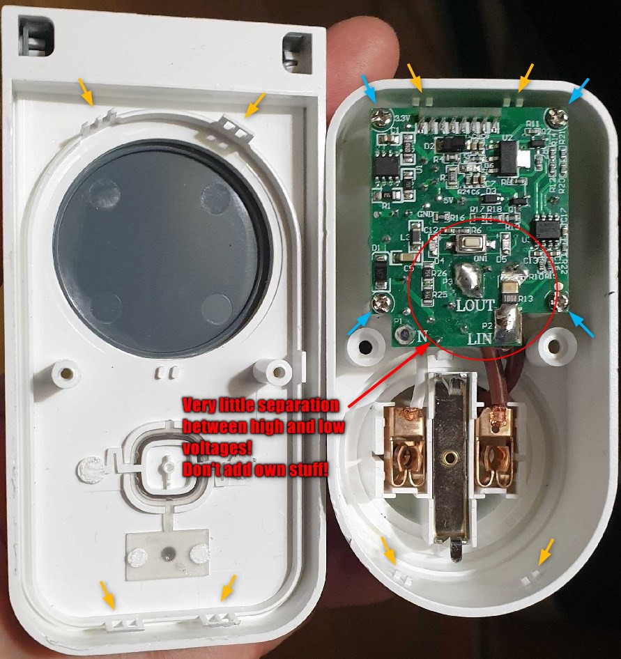
WARNING2! As always, never flash or connect serial wires when connected to mains voltage. Don't add DIY modifications unless you know exactly what you are doing. Small voltage pins tend to be more or less connected to mains voltage so depending on which way you plug the thing they may have lethal voltage.
One of the rare outdoor WiFi sockets with power measurement I could find was Nedis WIFIPO120FWT, which is not as trivial flashing target, but can be flashed using the equipment described here. These do have an ESP8266 module by Tuya, which support OTA flashing, often with Tuya Convert, but seems Tuya has changed something to not be compatible with Tuya Convert and it didn't work with my devices.
The most difficult part is getting the thing opened - the two tri-wings stop most people who shouldn't be opening them, but you and me will just pick a 2 mm flat screwdriver or whatever fits the best (a 2 mm tri-wing tip would be cheating, right?), then comes the more difficult part of prying the case open. Credit card and flat steel device opening tools will just bend, larger flat screwdriver(s) or table knife(s) and more brute force than feels comfortable are needed to pry open the case, hopefully without cracking all the clips (of the two I opened, only broke one of four tabs in both).
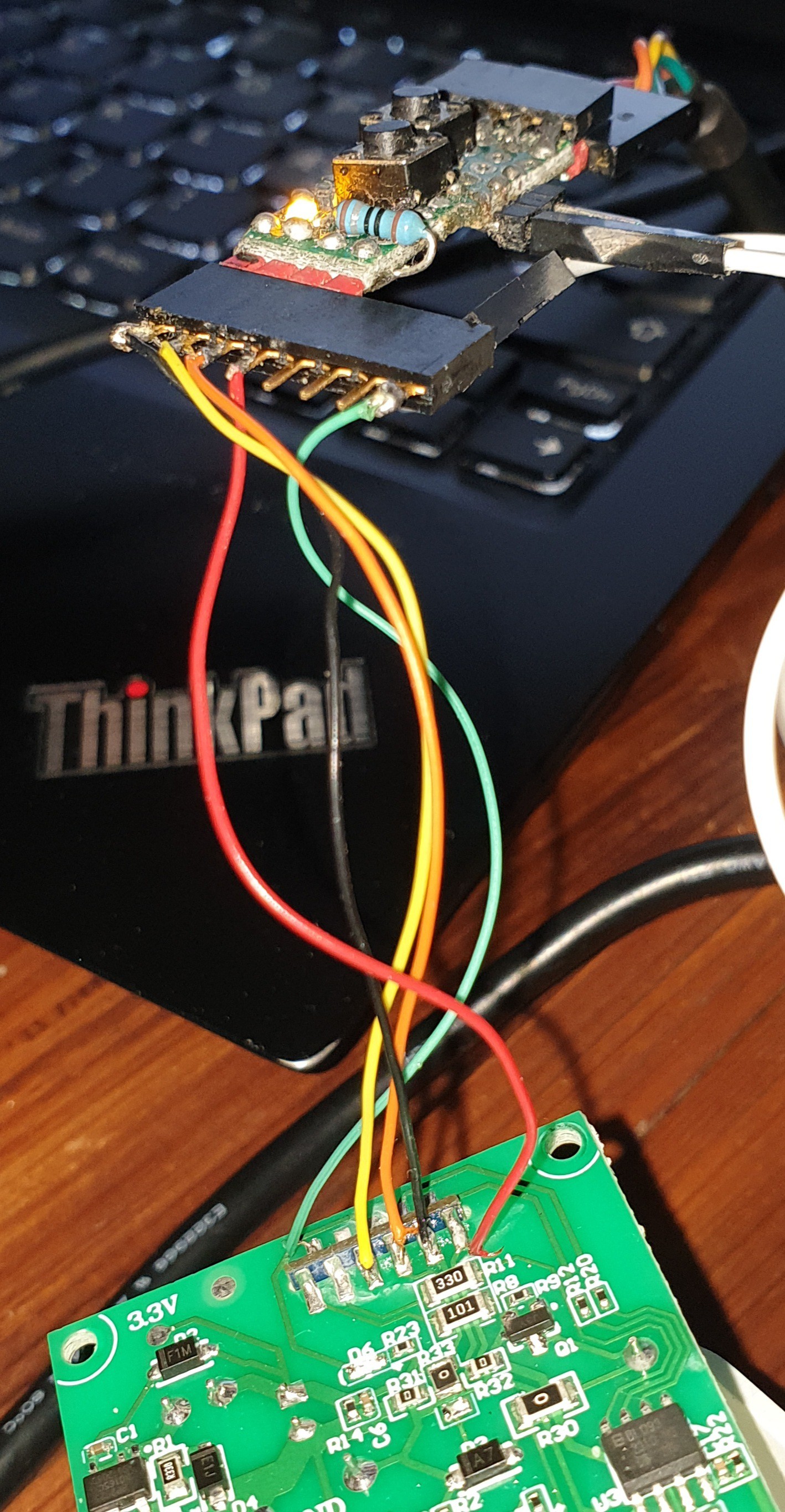
Inside you'll find a "TYWE3S" ESP12 clone by Tuya, with a shotgun-designed collection of test pads. For flashing several devices some printed jig would be recommended, for one or two soldering might be the easiest choice, or the SHP6 Pro adapter can be used like in the photo above, wired to the Universal Flasher using male-female dupont wires according to the photo. Pressing/hitting/drilling some small indentations in the test pads does ease placing the pins a lot, a spring loaded center punch or Dremel with a small tip might be easiest (the second one I did didn't take many seconds even with smooth pads - first bend them to very roughly match the pattern, then press the bunch on the PCB, then while keeping pressure with a screwdriver/whatever push the pins to their spots one by one).
I needed to repeat flashing process some times until getting to 100%, apparently happens with these Tuya modules. They seemed working better with GPIO 0 grounded (the button pressed) while flashing, but that probably just helps aligning sun spots.
The third of these devices I flashed by soldering wires instead of the "pogo comb"; IMHO easier as the pads are far from each other thus easy to solder with wrapping wire or similar:
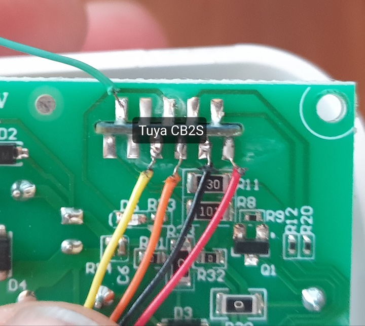
My non-ESP PO120 has a CB2S module but the Tasmota device registry at Blackadder says there are ones with CB3S, which is harder to replace (ESP-12E/F -style package).
The one I got has a CB2S module that happens to be compatible with ESP8285 based TYWE2S modules so can replace and install your favorite ESP firmware.
This is for ones with CB2S and the power measure chip BL0937, there may be other versions.
Tx = GPIO1 is the only pin for custom use. As mentioned, DO NOT route them or anything else outside the case however, as the low voltage lines are directly connected to mains voltage without any separation, always consider them having deadly voltage. A DS18B20 sensor tested working fine in TX/GPIO1 when pulled up with a 4k7 resistor, such a sensor can be hot glued to a corner of the case away from the ESP and relay, or next to the AC socket if its temperature is of concern.
Another option is a Tasmota-style firmware for these Beken and similar MCUs called OpenBeken, flashing is easy with the nifty GUIFlashTool using just Gnd+3V3+Rx+Tx(+Reset). With the Universal ESP flasher the reset line doesn't really add value, could use a row of pogos to interface the four needed pads but as this was my first Beken to flash I soldered wires.
8
Flashing Sonoff Mini
The Sonoff Mini (here V2 but the flashing pad layout is the same than V1) is a tiny relay board that can be hidden behind light switches or small connecting block boxes. They have a "DIY mode" for OTA flashing, but they are trivial to open (by screwdriver/credit card/fingernail/whatever) and trivial to flash with the tools presented here, the "DIY mode" process sounded much more complicated.
The pad order is different from the original Sonoff thus some DuPont proto wires are needed. I didn't connect GPIO0 as there is a button for that readily on the other side, but wiring one pogo there (marked "KEY_IN" in my boards) would actually make it easier to handle as then could just have the device on the table, pads pointing up, and less awkward to do the GPIO0-power on sequence with one hand. The pins are rather close together, I suggest checking continuity between the pogos before attaching wires. My pogos were not touching each other but they were really close.
As always, make sure AC is not connected while flashing or even opening the case, strongly suggest unscrewing all wires from the screw connectors.
Before flashing, put the device to flashing mode by keeping the Mini's button or adapter boards GPIO button, if a pogo connected to the GPIO0 pad KEY_IN, pressed while powering / restarting the device.
The BW-SS5 is like a very much like the Sonoff Mini, but has a version with two switch inputs and relays. Beware there is also a 1-gang version with the same exact model number, I wish they used sensible product numbering where from the model you'd know what you get.
MoesHouse MS-104B is apparently pretty much the same device but not exactly, I don't know if it looks the same inside.
This module has an LM1 ESP8266-module with a nice row of via pads for flashing:
Could sure use the pogo comb too but male DuPont pins are more convenient as there are holes wide enough for them and they don't need much holding.
The BW-SS5 and MS-104B have AC switch detection circuitry with rectified AC guiding the input GPIOs instead of digital high/low. This means the MCU will see a constant stream of pulses for "On" and no or less (long cables do cause inductive coupling, so AC on one wire will cause AC to the other wire as well) for "Off". Tasmota has a special mode for this, "SwitchDebounce xxx9", "xxx" being centiseconds (10 ms each) and "9" meaning we want xxx cs long pulse streams or lack of to turn the switch on/off. Most documentation mention "69" as a suitable starting point but I had to increase that to 209 to work properly, thus the command would be "SwitchDebounce 209".
10
Flashing Shelly Plus & Pro devices
Shellys have pretty good firmware, MQTT control and all, but still limited compared to Tasmota. The Plus and Pro (DIN rail) series are new versions based on ESP32 having scripting also in their original firmware so probably could be scripted to do what Tasmota can, but requires learning the language and API. To use as remote programmable thermostats I'm using just the simple Tasmota "rules" as they do the job and work the same with any 8266 or 32.
Warning: Dunno if the ethernet port in Pro devices works with Tasmota.
Plus 1PM with the Shelly Plus Add-On can be used as an electrically safe (galvanic isolation between sensor and the switch) computer controllable power measuring thermostat, which is exactly what I want for all the heaters, and I don't know any options outside the Shelly family. With Tasmota I can remotely control the thermostat temperature, assign a virtual "relay" to control between two temperatures -low for minimum stand-by temperature and high for cheap electricity/need to heat the space/prepare for cold nights- and change between those with the hardware button or internal timers, not depending on any external resources like network.
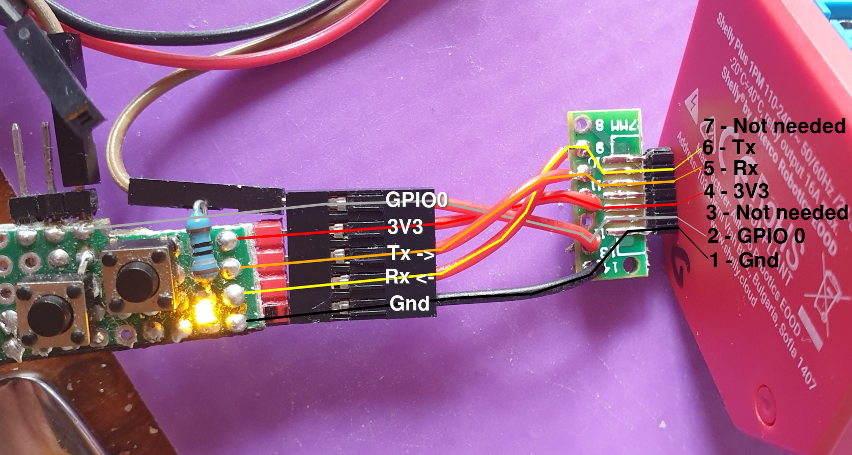
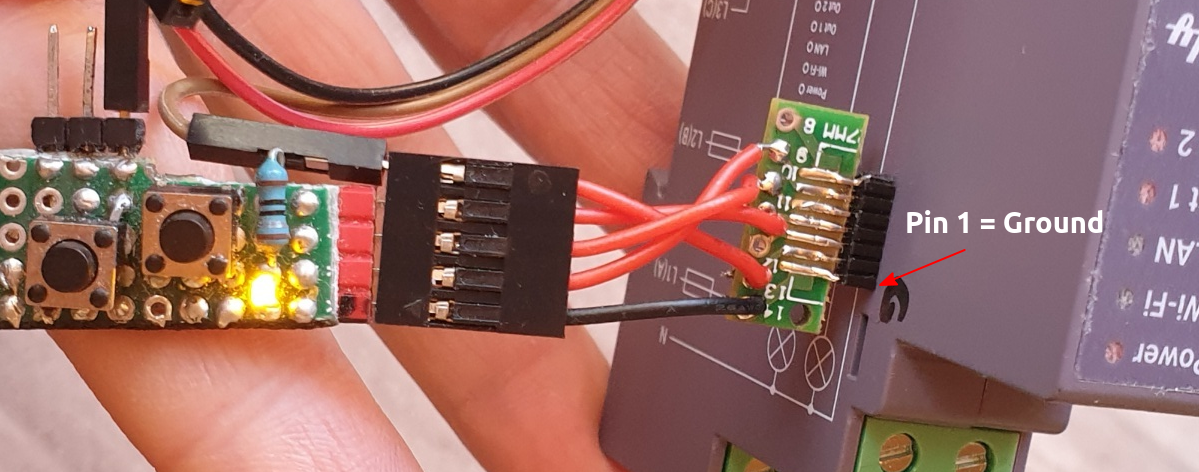
Most Shellys are hacker friendly, in addition to versatile firmware they can be flashed with whatever you like without even opening them. Many Shellys also can be OTA flashed very simply by entering a suitable URL in a browser and serial programming is also simple as older Shellys have a row of 2.54 mm holes under a cap and Plus/Pro models (ESP32) have a row of 1.27 mm holes that one might not even notice.
The adapter was built from a DuPont 5-pin female wired to a SOP/SSOP14 / DIP adapter cut in half (versatile boards BTW) with a piece of 1.27 mm male header. With this adapter board could also use short pieces of single strand wire instead of the header, just push the pieces into the holes (can omit the 2 unused ones), position on the adapter board and solder.
Flash as usual, keep GPIO0 pressed while rebooting, flash. If doesn't work try keeping pressed until flashing started. If still doesn't work, open a terminal emulator to this port and see what does it tell. ESP32-SOLO-1 should be the correct Tasmota flavor. These are ESP32 so use something supporting that like ESP_Flasher.
Hi! Thanks for the correction about the Nedis template, seems that this form with "133" is the one my devices use as well. Somehow I had copied this line from another place without noticing it's not the same I use. There may be different versions of this device with different measurement chips.
50 mA is not enough to run an ESP8266 with radio on, which they generally have when booted up. Apparently this 50 mA is the promised minimum "at least" current any individual chip can deliver in any condition and normally they can deliver much more. Also, the ESP is happy with much lower voltages, down to about 2.5 Volts, thus the voltage regulator not being able to keep the voltage may not be a deal killer. Anyway, with that low specifications, for reliable flashing I recommend using a dedicated regulator, LDO or buck, that can deliver at least 250 mA.
I didn't mention software, as the tools presented here are software agnostic; doesn't matter what firmware you flash and with which tool. However, now I added pointers to some firmware and flashing tool options, as those obviously are relevant when you want to free your devices from the leash.
Thank you for this post. It gave me a push to first purchase the plug and then to make the Tasmota upgrade. OTA was not possible. The suggested template gave me the wrong voltage however.
For my unit (Nedis outdoor switch WIFIPO120FWT) the following seems to work: {"NAME":"WIFIPO120FWT","GPIO":[17,0,0,0,133,132,0,0,131,56,21,0,0],"FLAG":0,"BASE":49}
FYI. I used a stock 5V/3V3 FTDI device (switchable by bridging pins). I checked the specification of the FTDI chip. It can output 50 mA through the 3V3 pin. And this was apparently enough.
At first I had problems with one of my USB cables. A high quality cable is adviced.
 Turo Heikkinen


Discussions
Become a Hackaday.io Member
Create an account to leave a comment. Already have an account? Log In.
Hi! Thanks for the correction about the Nedis template, seems that this form with "133" is the one my devices use as well. Somehow I had copied this line from another place without noticing it's not the same I use. There may be different versions of this device with different measurement chips.
50 mA is not enough to run an ESP8266 with radio on, which they generally have when booted up. Apparently this 50 mA is the promised minimum "at least" current any individual chip can deliver in any condition and normally they can deliver much more. Also, the ESP is happy with much lower voltages, down to about 2.5 Volts, thus the voltage regulator not being able to keep the voltage may not be a deal killer. Anyway, with that low specifications, for reliable flashing I recommend using a dedicated regulator, LDO or buck, that can deliver at least 250 mA.
I didn't mention software, as the tools presented here are software agnostic; doesn't matter what firmware you flash and with which tool. However, now I added pointers to some firmware and flashing tool options, as those obviously are relevant when you want to free your devices from the leash.
Are you sure? yes | no
Thank you for this post. It gave me a push to first purchase the plug and then to make the Tasmota upgrade. OTA was not possible.
The suggested template gave me the wrong voltage however.
For my unit (Nedis outdoor switch WIFIPO120FWT) the following seems to work:
{"NAME":"WIFIPO120FWT","GPIO":[17,0,0,0,133,132,0,0,131,56,21,0,0],"FLAG":0,"BASE":49}
Found this template at https://templates.blakadder.com/nedis_WIFIPO120FWT.html
FYI. I used a stock 5V/3V3 FTDI device (switchable by bridging pins). I checked the specification of the FTDI chip. It can output 50 mA through the 3V3 pin. And this was apparently enough.
At first I had problems with one of my USB cables. A high quality cable is adviced.
Also, there is no mention of any software in this post. I suggest https://github.com/tasmota/tasmotizer, worked flawlessly for me.
Finally free from the cloud!
Are you sure? yes | no