-
1Building premises.
I'm going to enumerate some important concepts i have taken into account for the robot design.
- This robots depends hardly on its mass distribution and dynamics of the moving parts (legs). Thats why i decided to go for this servo configuration, having the coxa servo on the body, the femur servo on the coxa and tibia servo on the the femur, so there is only 2 servos moving with the legs.
![]()
- This way, the less leg weight the less unexpected inertia, causing a better dynamic behavior.
- Also the robot weight should be as less as posible becouse hobby servos can be overcharged easily.
- About the mass distribution, this would define the Center of Mass which should be the closest to the Geometric Center, for this the building must be as simetric as posible, this way CoM is easier to locate and the control would be more predictable.
- The lenght of the leg is defined at 100 mm for both tibia a femur, this way, a motor with 20 Kg/cm will hold 2 kg at a 10 cm arm. So the longer the arm, the less force the motor can support.
- Avoid plastic vs plastic joints, this would involve unnecessary friction forces.
Printing premises.
- This is simple but is important to take this into account, at the time of printing, these parts are not supporting much mechanical forces, for this and taking into account building premises, the 3D printed parts should be printed with ~10-20% infill , 1-2 outer perimeters and 2-3 solid layers.
-
2Building and printing the robot.
For building this i have made this tutorial, as there are some tricky parts.
In the file section, each STL is named with the quantity of parts you need to print, if none just one needs to be printed.
Also you can download files all at once at the file section, file STL_files.zip.
If you are building the robot, take into account this:
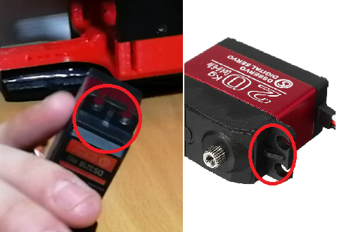
Some servos has a small ridge in the holding holes for making this part stronger, for my desing i did cut these small ridges in order to make the parts easier to print and design.
![]()
Bolt list:
- M3 x45 mm: quantity12
- M3 x30 mm: quantity26
- M3 x25 mm: quantity16
- M3 x20 mm: quantity8
- M3 x15 mm: quantity16
- M3 x7 mm: quantity4
- M3 threaded rod x 42 mm: quantity4
- M3 threaded rod x 74 mm: quantity8
Plus its respectives nuts and washers where is needed.
-
3Electronics.
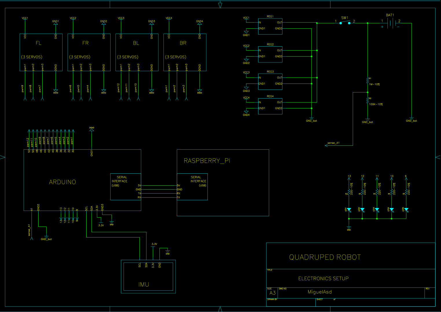
Here is the electronics setup i have:
![]()
You can download the full size PDF file of the scheme at the file section.
As you can see, appart from the 4 power lines in order to power the servomotors, there is also a voltage divider in order to read the batterie voltage in the arduino from an analog pin and then 5 LEDs will indicate the batterie status. Finally, IMU is connected via I2C interface. Raspberry pi is powered via another bulk converter at 5V 3A, that i miss (i will correct this in the next updates) and arduino communicates via USB cable (which also power it) to raspberry pi.
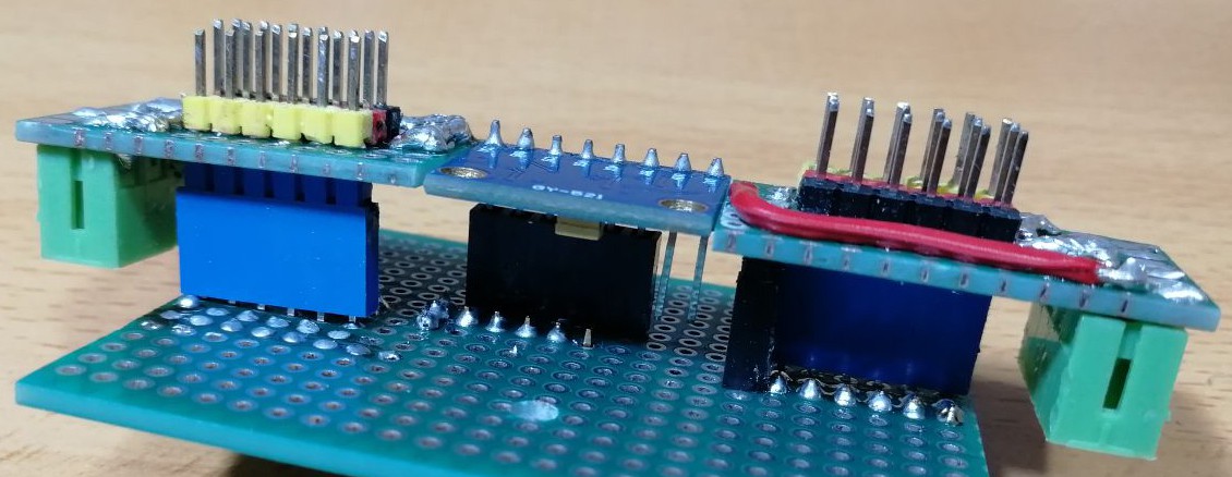
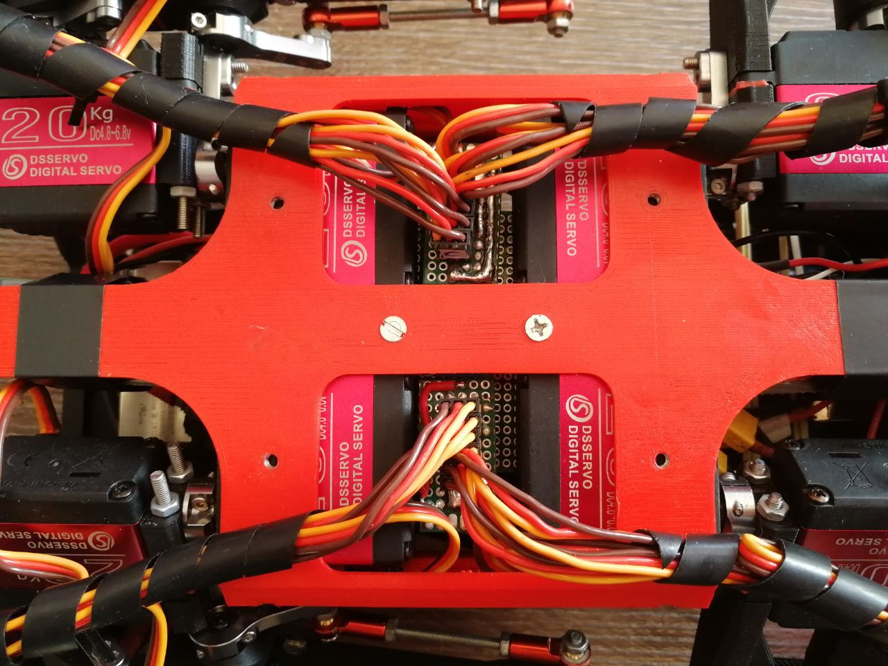
I made two modular small boards in order to easily connect and disconnect servos, these boards are conected to the big one, which will supply all the pins to the arduino, being the 12 pwm signals with its commun ground and the I2C interface for the IMU. Also here, i can add sensors (FRS) the same way for the future.
Details of the building:
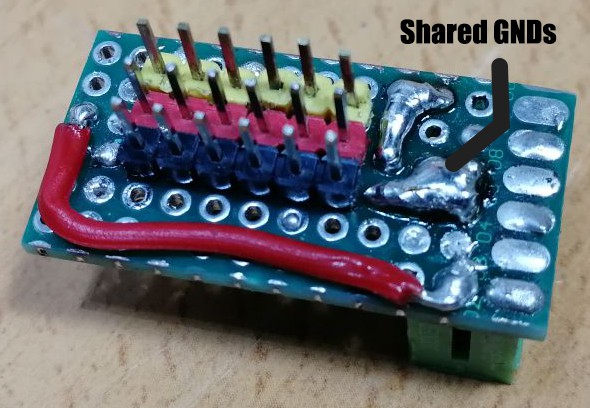
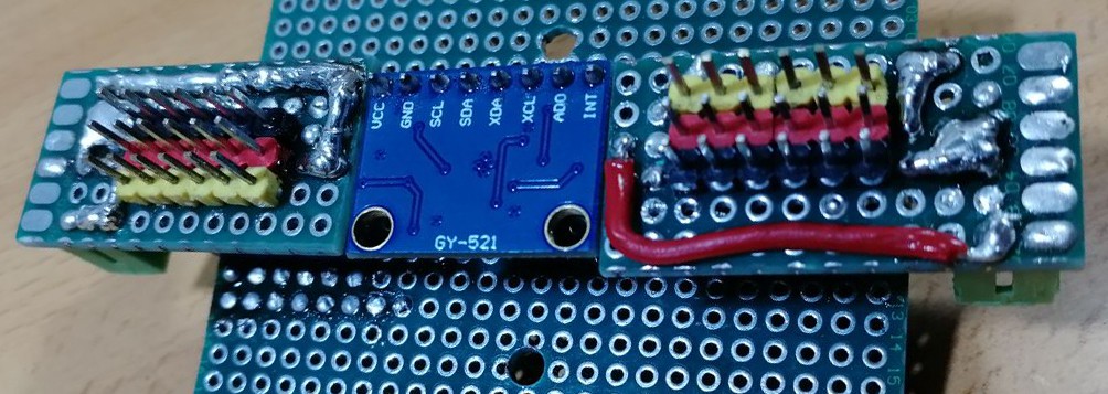
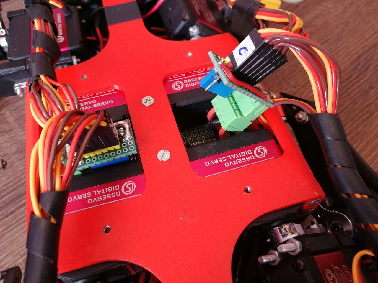
- Starting from the small board that supplies the servo power and the digital signal for the arduino, they have shared GNDs and are divided into 4 different lines, one for each bulk converter. They are connected to the main board, which accommodates the IMU and two of these boards.
![]()
![]()
![]()
![]()
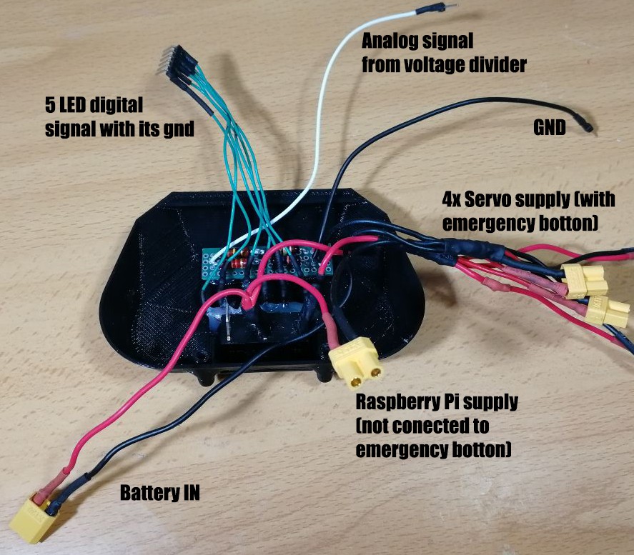
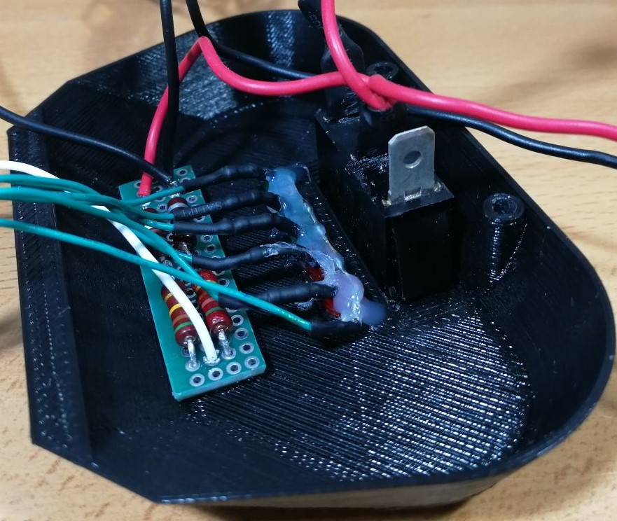
- The other components that accomodates some electronics is the back cover of the robot, where the Emergency Botton is placed along with the 5-LED battery indicator, also the voltage divider in orther to read the battery voltage is placed here, attached with some hot glue.
![]()
![]()
![]()
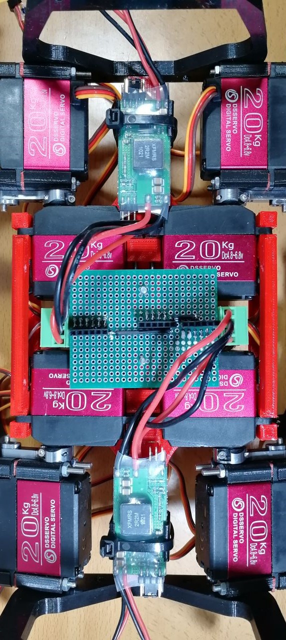
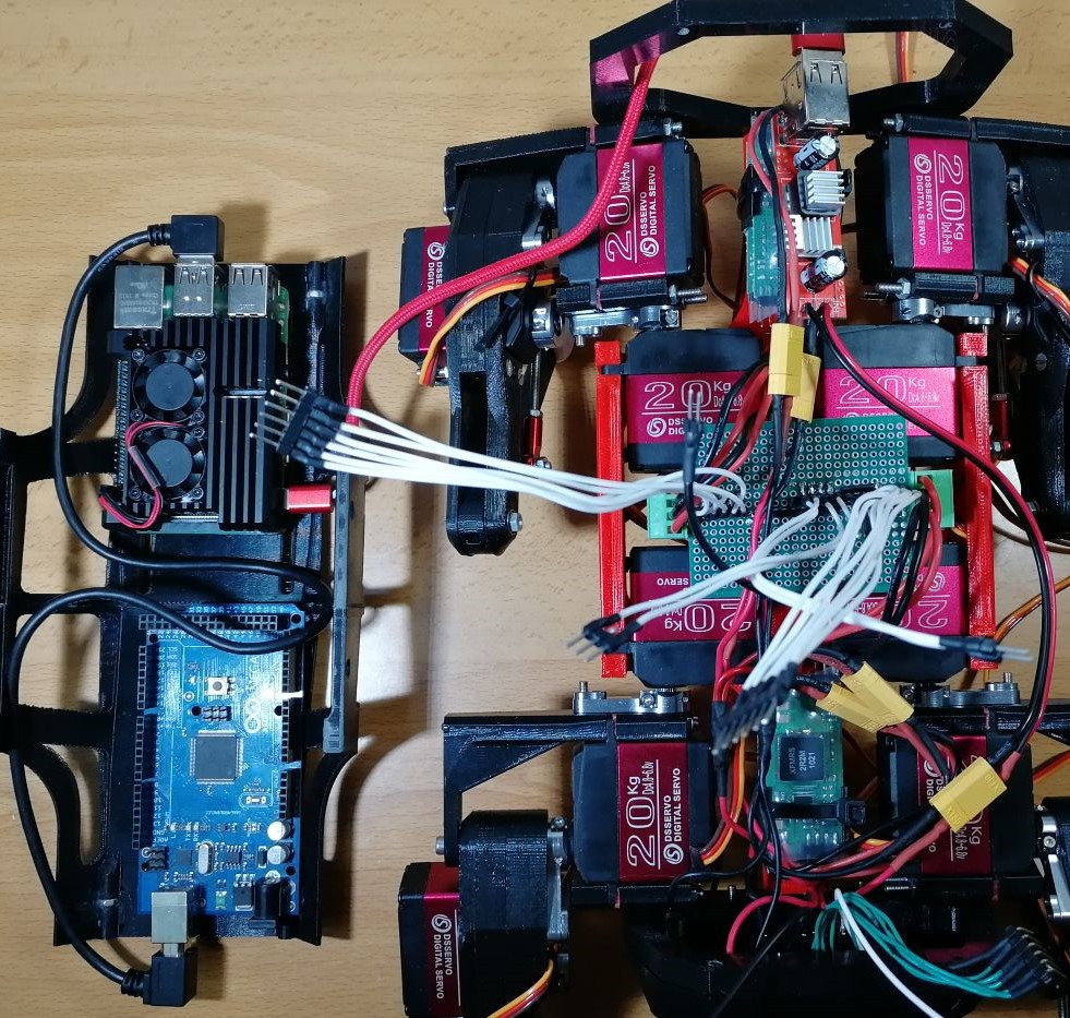
- Finally everything is prepared to be mount, notice that bulk converters are placed between the fermur servos and attached with tape. Also, you can see how Raspberry Pi and Arduino MEGA are attached to the top of the robot.
![]()
![]()
![]()
![]()
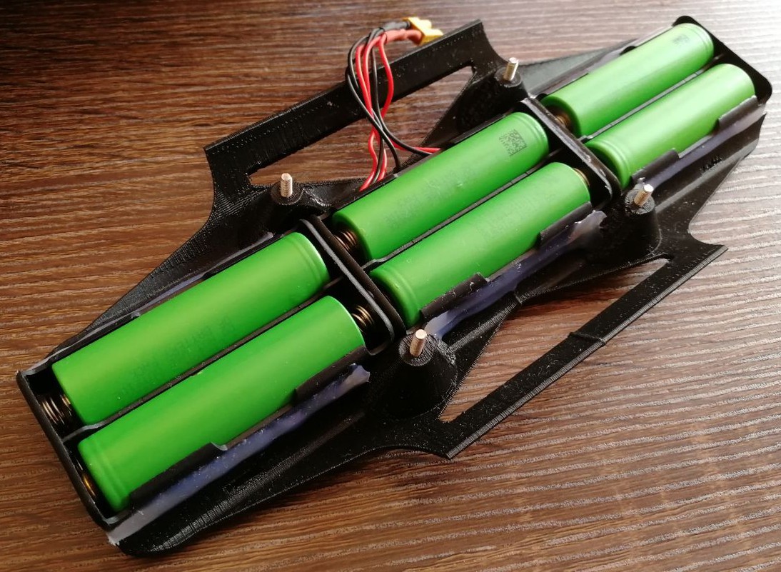
- Finally, the battery is made with individual cells, so i have to charge them one by one.
![]()
DIY hobby servos quadruped robot
Cheap 3D printed 4 legged robot, that almost looks like boston dynamics spot but moves like a newborn.
 Miguel Ayuso Parrilla


Discussions
Become a Hackaday.io Member
Create an account to leave a comment. Already have an account? Log In.
Great project! I have already started assembling it and finished with the mechanics. I see the arduino code on the github, but where can I find the program for the Raspberry Pi and instructions for installing it?
Are you sure? yes | no
Hi Thats awesome, hope you enjoy they job! Raspberry code just in the main branch of repository. https://github.com/miguelasd688/4-legged-robot-model
Main program: robot_main_RPI.py and all sources at /src folder. There are no instructions for raspberry pi and you would need to have the skill to understand the code, as you would need to do calibration manually as exposed in its log: https://hackaday.io/project/171456-diy-hobby-servos-quadruped-robot/log/181663-calibrating-the-servos
Are you sure? yes | no
This is so awesome. Is this project going to continually be improved or was it just a fun project? And is the code your own or based on another project such as the Open Dynamic Robot Initiative? Time to start ordering the BOM!
Are you sure? yes | no
I was making cables from breakaway headers like the white cables in your pictures. If you get a crimping tool and a set of headers like these, you'll probably really like the result.
* Crimp pliers: https://www.sparkfun.com/products/13193
* Header set: https://www.amazon.com/gp/product/B014YTPFT8
* Cable (of some sort): https://www.sparkfun.com/products/10647
Are you sure? yes | no
Nice, thanks for suggest and pointing it out! I used what i had by home
Are you sure? yes | no
Can you add the STL files to your repo? Hackaday makes me click each one to download, which is dumb.
Are you sure? yes | no
Thanks for the advice Caleb, here they are: https://github.com/miguelasd688/4-legged-robot-model/tree/master/3D-printable-files
Are you sure? yes | no
Awesome!!! I've been slowly getting all the pieces together to try this build. This will really help. Thanks!
Are you sure? yes | no