-
Improving the leg mechanism and new PCB board.
11/01/2022 at 02:17 • 0 commentsIt's been a while since I don't update the project but it doesn't mean I've stopped working on the robot ;)
About the code, there is still a very primivite version of the model at Github. I've been also improving it but still some cleaning up of the code needed as I want to show it clear to understand. Hope on next months it cound be done!
You can check further updates on Instagram
Desinging a PCB board
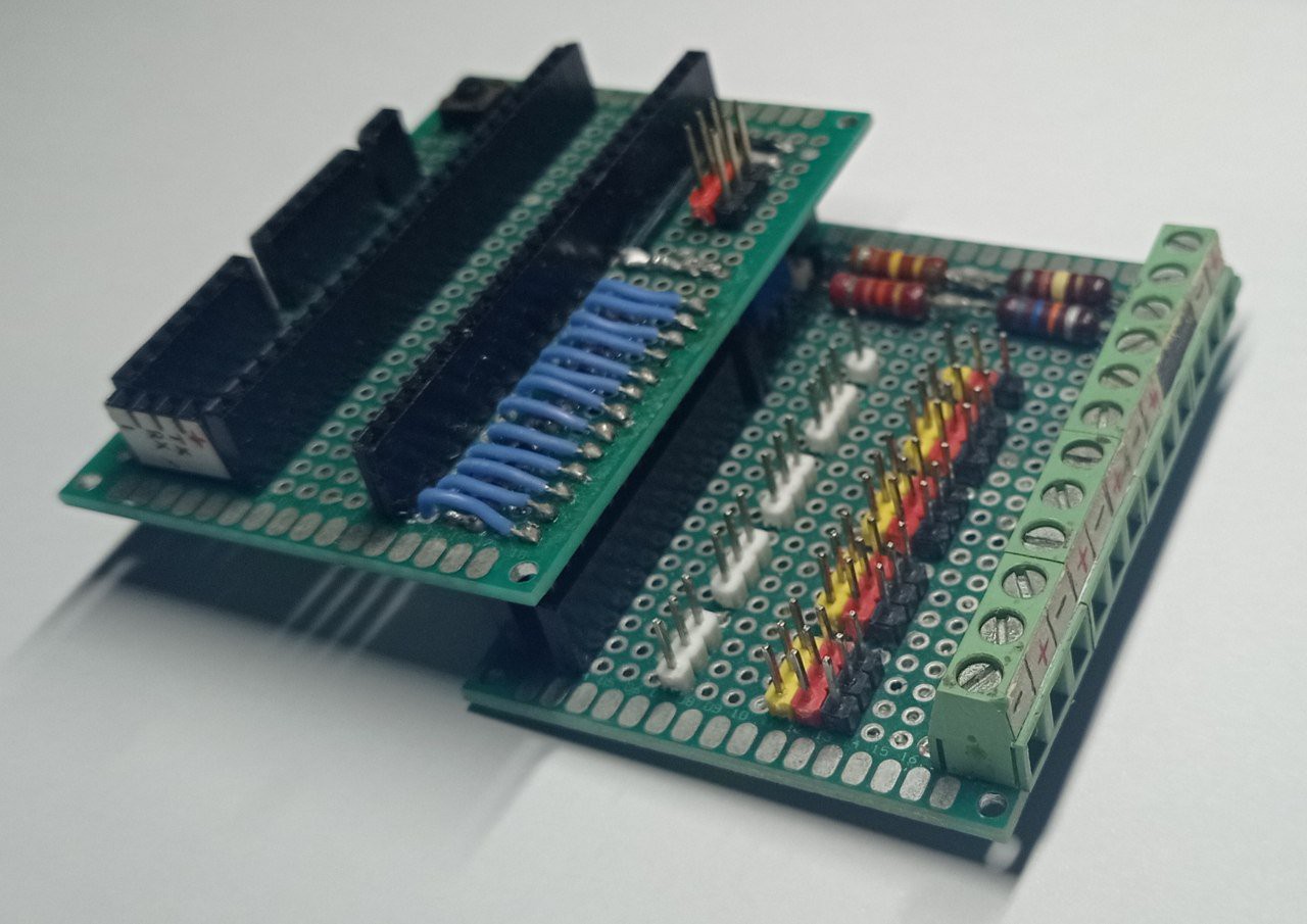
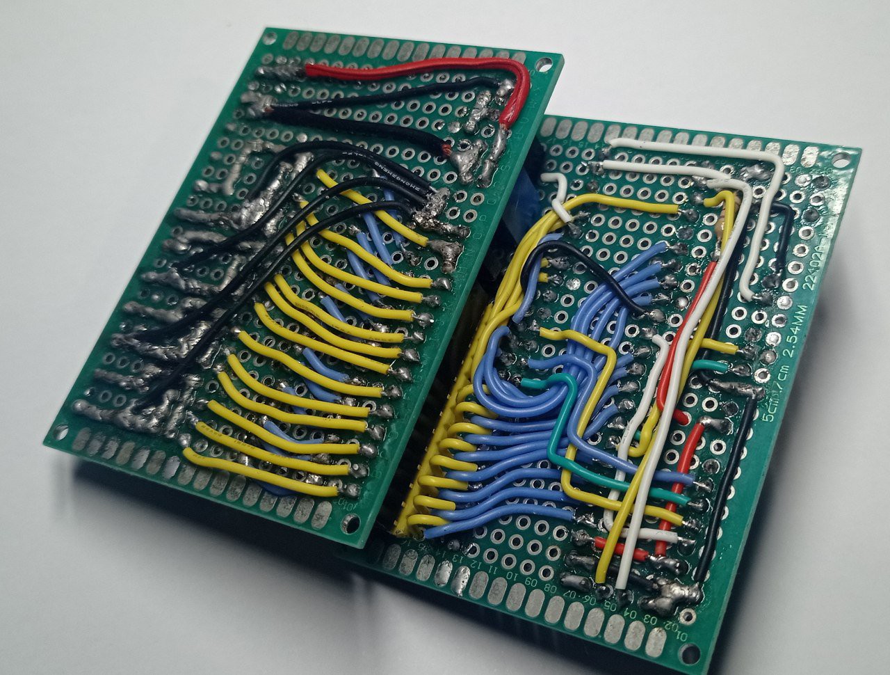
I want to share PCB I made to interface all conections. Making wiring by hand is always tedious and it can be cosidered like an art.
![]()
![]()
But now is very easy to design and manufacture your own PCBs for a very small budget.
![]()
![]()
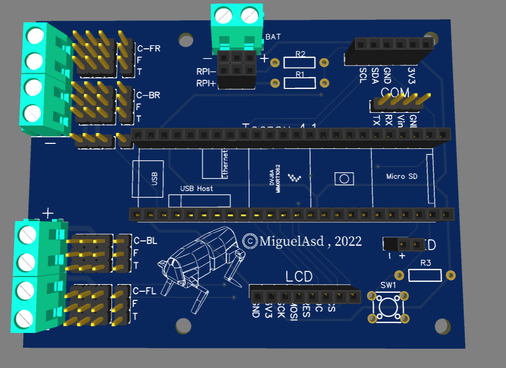
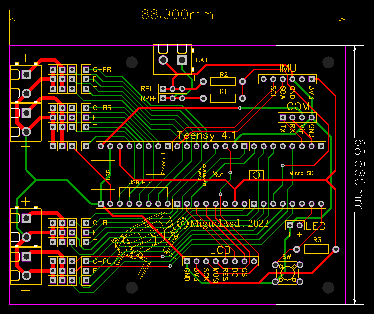
The board is very simple and make the wiring job very straight forward. The carateristics are:
- Teensy 4.1 interface. It is very fast, which can handle even LCD and achieve high frequency.
- I2C bus for 9-DOF Absolute Orientation IMU, bno055 in my case.
- Serial tx/rx and Vin to power Teensy.
- 13 servo connections divided in 4 different power supply.
- 13 analog input, in other to read each servo's potentiometer.
- Voltage divider to read battery voltage.
- 3V3 output.
- Push button.
ATTENTION!: If powering Teensy through 5V pin power supply, don't connect USB supply. As both voltage at the same time can damage microcontroller.
Manufacture it is very easy now, Thanks to PCBway we get high quality PCB plus very good service, solving any manufacturing doubt very fast. It was very easy to order the boards!
You can get PCB files here.
![]()
________________________________________________________________________________
Improving the leg mechanism.
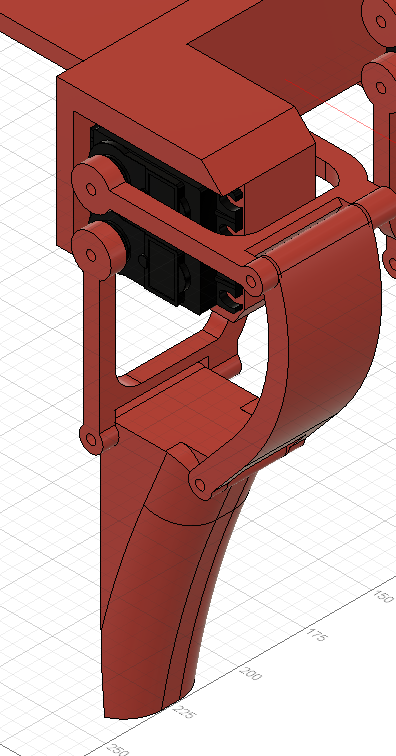
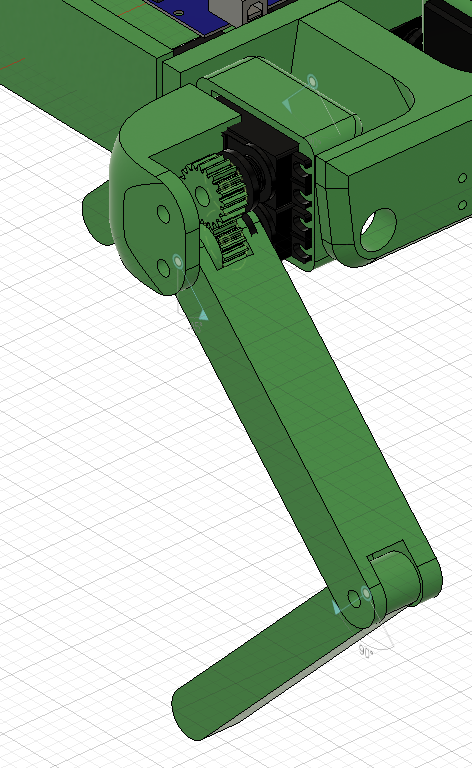
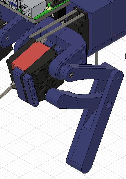
Along this 3 years I have been trying several leg mechanism.
![]()
![]()
![]()
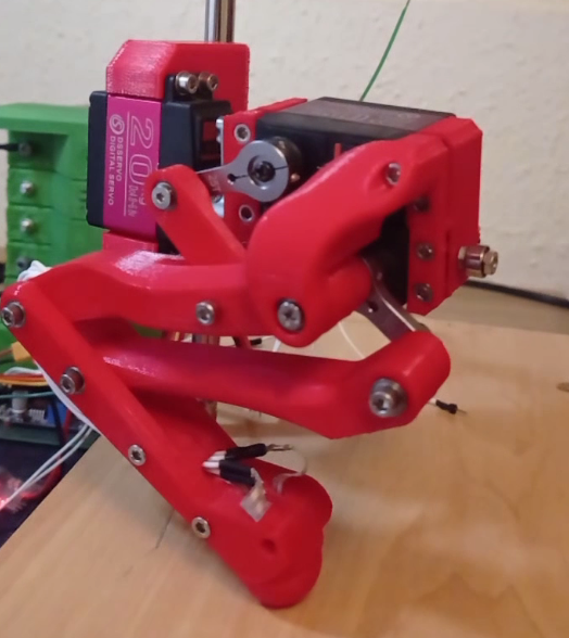
Finally I decided to do a simple design with tibial motor placed on the femur joint.
![]()
But this design still had several problems, like it wasn't very robust and the most importat is that having the motor (with big mass) that far from the rotating axis, caused in fast movements, unwanted dynamics to the robot body, making controlability worse.
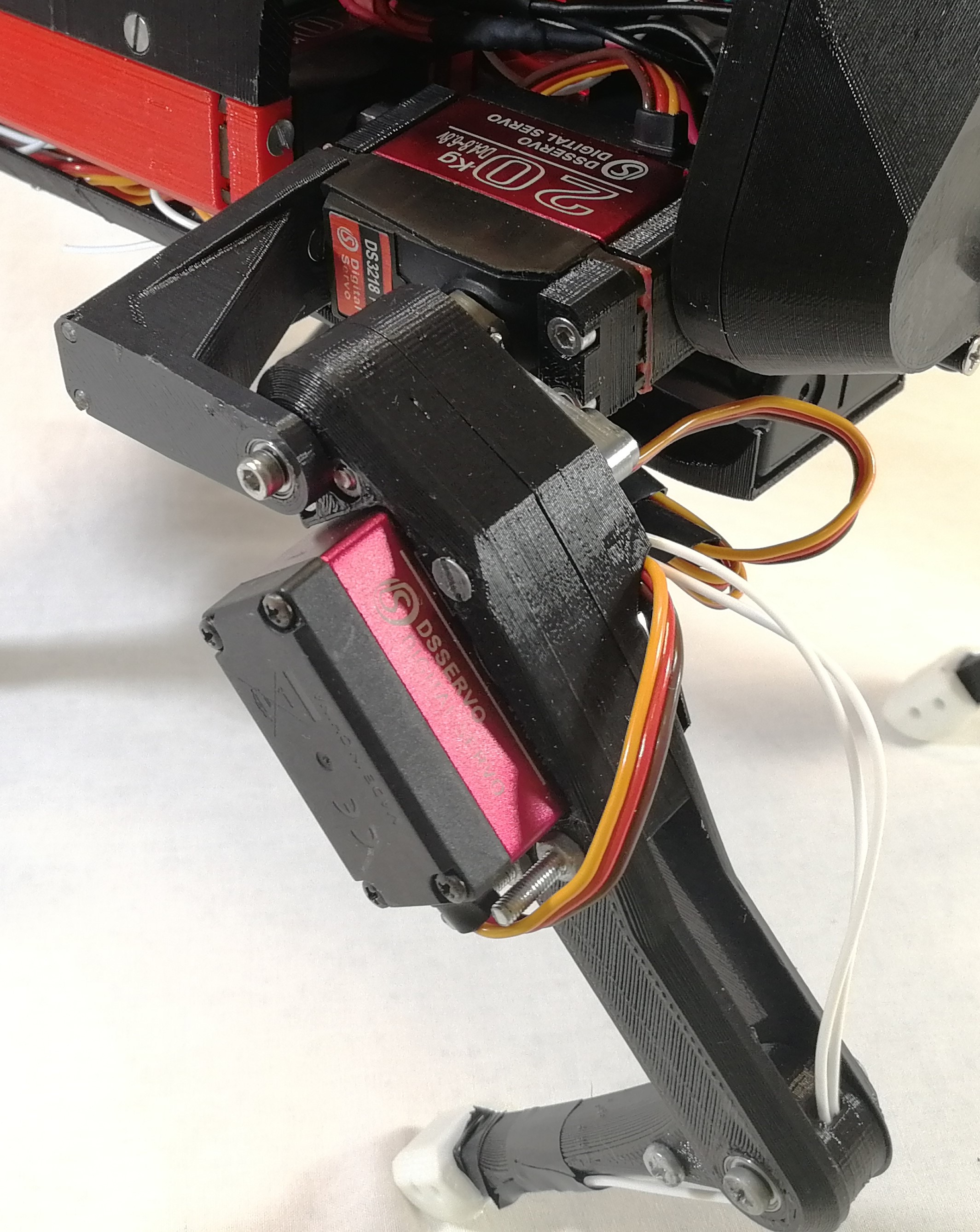
New version have both motors of femur/tibial limb at coxa frame, this ends with a very simple setup and at the same time, the heaviest masses of the mechanism are centered to the rotating axis of coxa limb, so even though the leg do fast movements, inertias won't be strong enough to affect the hole robot mass, achieving more agility.
![]()
Inverse Kinematics of the mechanism
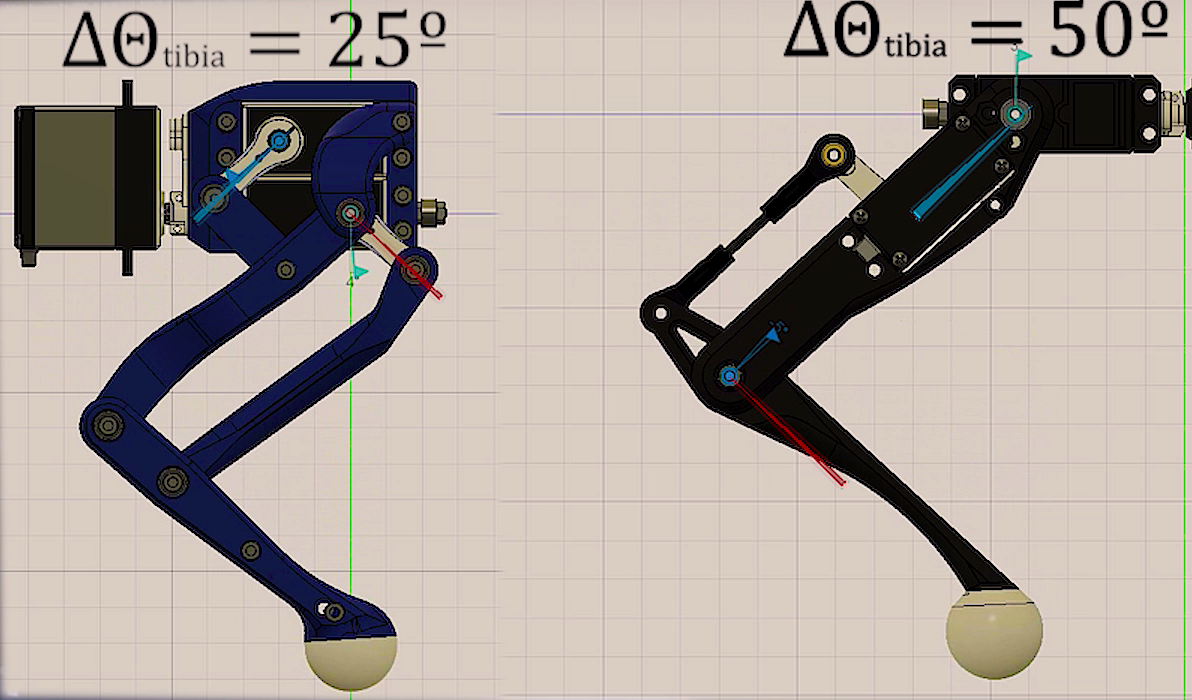
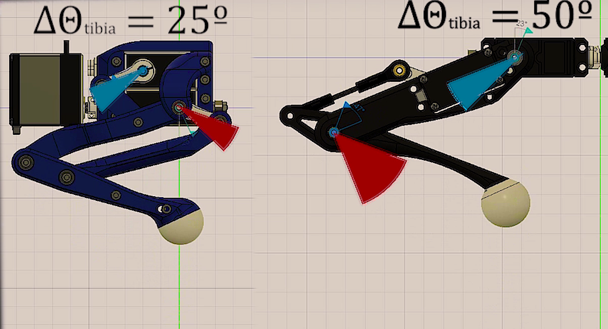
After building it I notice that this mechanism was very special for another reason, at the domain the leg normally moves, it acts as a diferential mecanism, this means that torque is almost all the time shared between both motor of the longer limbs. That was an improvent since with the old mechanism tibial motor had to hold most of the weight and it was more forced than the one for femur.
To visualize this, for the same movement, we can see how tibial motor must travel more arc of angel that the one on the new version.
![]()
![]()
In order to solve this mechanism, just some trigonometry is needed. Combining both cosine and sine laws, we can obtain desired angle (the one between femur and tibia) with respect to the angle the motor must achieve.
Observing these equations, with can notice that this angle (the one between femur and tibia) depends on both servos angles, which means both motors are contributing to the movement of the tibia.
Calibration of servos
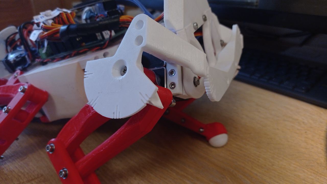
Another useful thing to do if we want to control servo precisely is to print a calibration tool for our set up. As shown in the image below, in order to know where real angles are located, angle protactor is placer just in the origin of the rotating joint, and choosing 2 know angles we can match PWM signal to the real angles we want to manipulate simply doing a lineal relation between angles and PWM pulse length.
Then a simple program in the serial console can be wrtten to let the user move the motor to the desired angle. This way the calibration process is only about placing motor at certain position and everything is done and we won't need to manually introduce random values that can be a very tedious task.
![]()
With this I have achieved very good calibrations on motors, which cause the robot to be very simetrial making the hole system more predictable. Also the calibration procedure now is very easy to do, as all calculations are done automatically. Check Section 1 for the example code for calibration.
SECTION 1:
---------- more ----------In the example code below, you can see how calibration protocol works, it is just a function called calibrationSecuence() which do all the work until calibration is finished. So you only need to call it one time to enter calibration loop, for example by sending a 'c' character thought the serial console.
Also some useful function are used, like moving motor directly with analogWrite functions which all the calculations involved, this is a good point since no interrupts are used.
This code also have the feature to calibrate the potentiometer coming from each motor.
#define MAX_PULSE 2500 #define MIN_PULSE 560 /*---------------SERVO PIN DEFINITION------------------------*/ int m1 = 6;//FR int m2 = 5; int m3 = 4; int m4 = 28;//FL int m5 = 29; int m6 = 36; int m7 = 3;//BR int m8 = 2; int m9 = 1; int m10 = 7;//BL int m11 = 24; int m12 = 25; int m13 = 0;//BODY /*----------------- CALIBRATION PARAMETERS OF EACH SERVO -----------------*/ double lowLim[13] = {50, 30, 30, 50, 30, 30, 50, 30, 30, 50, 30, 30, 70}; double highLim[13] = {130, 150, 150, 130, 150, 150, 130, 150, 150, 130, 150, 150, 110}; double a[13] = { -1.08333, -1.06667, -1.07778, //FR -1.03333, 0.97778, 1.01111, //FL 1.03333, 1.05556, 1.07778, //BR 1.07500, -1.07778, -1.00000, //BL 1.06250 }; double b[13] = {179.0, 192.0, 194.5, //FR 193.0, 5.5, -7.5, //FL 7.0, -17.0, -16.0, //BR -13.5, 191.5, 157.0, //BL -0.875 }; double ae[13] = {0.20292, 0.20317, 0.19904 , 0.21256, -0.22492, -0.21321, -0.21047, -0.20355, -0.20095, -0.20265, 0.19904, 0.20337, -0.20226 }; double be[13] = { -18.59717, -5.70512, -2.51697, -5.75856, 197.29411, 202.72169, 185.96931, 204.11902, 199.38663, 197.89534, -5.33768, -32.23424, 187.48058 }; /*--------Corresponding angles you want to meassure at in your system-----------*/ double x1[13] = {120, 135, 90, 60, 135 , 90, 120, 135, 90, 60, 135, 90, 110}; //this will be the first angle you will meassure double x2[13] = {60, 90, 135, 120, 90, 135, 60, 90, 135, 120, 90, 135, 70};//this will be the second angle you will meassure for calibration /*--------You can define a motor tag for each servo--------*/ String motorTag[13] = {"FR coxa", "FR femur", "FR tibia", "FL coxa", "FL femur", "FL tibia", "BR coxa", "BR femur", "BR tibia", "BL coxa", "BL femur", "BL tibia", "Body angle" }; double ang1[13] = {0, 0, 0, 0, 0, 0, 0, 0, 0, 0, 0, 0, 0}; double ang2[13] = {0, 0, 0, 0, 0, 0, 0, 0, 0, 0, 0, 0, 0}; float xi[500]; float yi[500]; float fineAngle; float fineL; float fineH; int motorPin; int motor = 0; float calibrationAngle; float res = 1.0; float ares = 0.5; float bres = 1.0; float cres = 4.0; float rawAngle; float orawAngle; char cm; char answer; bool interp = false; bool question = true; bool swing = false; int i; double eang; int freq = 100; // PWM frecuency can be choosen here. void connectServos() { analogWriteFrequency(m1, freq); //FR coxa digitalWrite(m1, LOW); pinMode(m1, OUTPUT); analogWriteFrequency(m2, freq); //femur digitalWrite(m2, LOW); pinMode(m2, OUTPUT); analogWriteFrequency(m3, freq); //tibia digitalWrite(m3, LOW); pinMode(m3, OUTPUT); analogWriteFrequency(m4, freq); //FL coxa digitalWrite(m4, LOW); pinMode(m4, OUTPUT); analogWriteFrequency(m5, freq); //femur digitalWrite(m5, LOW); pinMode(m5, OUTPUT); analogWriteFrequency(m6, freq); //tibia digitalWrite(m6, LOW); pinMode(m6, OUTPUT); analogWriteFrequency(m7, freq); //FR coxa digitalWrite(m7, LOW); pinMode(m7, OUTPUT); analogWriteFrequency(m8, freq); //femur digitalWrite(m8, LOW); pinMode(m8, OUTPUT); analogWriteFrequency(m9, freq); //tibia digitalWrite(m9, LOW); pinMode(m9, OUTPUT); analogWriteFrequency(m10, freq); //FR coxa digitalWrite(m10, LOW); pinMode(m10, OUTPUT); analogWriteFrequency(m11, freq); //femur digitalWrite(m11, LOW); pinMode(m11, OUTPUT); analogWriteFrequency(m12, freq); //tibia digitalWrite(m12, LOW); pinMode(m12, OUTPUT); analogWriteFrequency(m13, freq); //body digitalWrite(m13, LOW); pinMode(m13, OUTPUT); } void servoWrite(int pin , double angle) { float T = 1000000.0f / freq; float usec = float(MAX_PULSE - MIN_PULSE) * (angle / 180.0) + (float)MIN_PULSE; uint32_t duty = int(usec / T * 4096.0f); analogWrite(pin , duty); } double checkLimits(double angle , double lowLim , double highLim) { if ( angle >= highLim ) { angle = highLim; } if ( angle <= lowLim ) { angle = lowLim; } return angle; } int motorInfo(int i) { enc1 , enc2 , enc3 , enc4 , enc5 , enc6 , enc7 , enc8 , enc9 , enc10 , enc11 , enc12 , enc13 = readEncoders(); if (i == 0) { rawAngle = enc1; motorPin = m1; } else if (i == 1) { rawAngle = enc2; motorPin = m2; } else if (i == 2) { rawAngle = enc3; motorPin = m3; } else if (i == 3) { rawAngle = enc4; motorPin = m4; } else if (i == 4) { rawAngle = enc5; motorPin = m5; } else if (i == 5) { rawAngle = enc6; motorPin = m6; } else if (i == 6) { rawAngle = enc7; motorPin = m7; } else if (i == 7) { rawAngle = enc8; motorPin = m8; } else if (i == 8) { rawAngle = enc9; motorPin = m9; } else if (i == 9) { rawAngle = enc10; motorPin = m10; } else if (i == 10) { rawAngle = enc11; motorPin = m11; } else if (i == 11) { rawAngle = enc12; motorPin = m12; } else if (i == 12) { rawAngle = enc13; motorPin = m13; } return rawAngle , motorPin; } void moveServos(double angleBody , struct vector anglesServoFR , struct vector anglesServoFL , struct vector anglesServoBR , struct vector anglesServoBL) { //FR anglesServoFR.tetta = checkLimits(anglesServoFR.tetta , lowLim[0] , highLim[0]); fineAngle = a[0] * anglesServoFR.tetta + b[0]; servoWrite(m1 , fineAngle); anglesServoFR.alpha = checkLimits(anglesServoFR.alpha , lowLim[1] , highLim[1]); fineAngle = a[1] * anglesServoFR.alpha + b[1]; servoWrite(m2 , fineAngle); anglesServoFR.gamma = checkLimits(anglesServoFR.gamma , lowLim[2] , highLim[2]); fineAngle = a[2] * anglesServoFR.gamma + b[2]; servoWrite(m3 , fineAngle); //FL anglesServoFL.tetta = checkLimits(anglesServoFL.tetta , lowLim[3] , highLim[3]); fineAngle = a[3] * anglesServoFL.tetta + b[3]; servoWrite(m4 , fineAngle); anglesServoFL.alpha = checkLimits(anglesServoFL.alpha , lowLim[4] , highLim[4]); fineAngle = a[4] * anglesServoFL.alpha + b[4]; servoWrite(m5 , fineAngle); anglesServoFL.gamma = checkLimits(anglesServoFL.gamma , lowLim[5] , highLim[5]); fineAngle = a[5] * anglesServoFL.gamma + b[5]; servoWrite(m6 , fineAngle); //BR anglesServoBR.tetta = checkLimits(anglesServoBR.tetta , lowLim[6] , highLim[6]); fineAngle = a[6] * anglesServoBR.tetta + b[6]; servoWrite(m7 , fineAngle); anglesServoBR.alpha = checkLimits(anglesServoBR.alpha , lowLim[7] , highLim[7]); fineAngle = a[7] * anglesServoBR.alpha + b[7]; servoWrite(m8 , fineAngle); anglesServoBR.gamma = checkLimits(anglesServoBR.gamma , lowLim[8] , highLim[8]); fineAngle = a[8] * anglesServoBR.gamma + b[8]; servoWrite(m9 , fineAngle); //BL anglesServoBL.tetta = checkLimits(anglesServoBL.tetta , lowLim[9] , highLim[9]); fineAngle = a[9] * anglesServoBL.tetta + b[9]; servoWrite(m10 , fineAngle); anglesServoBL.alpha = checkLimits(anglesServoBL.alpha , lowLim[10] , highLim[10]); fineAngle = a[10] * anglesServoBL.alpha + b[10]; servoWrite(m11 , fineAngle); anglesServoBL.gamma = checkLimits(anglesServoBL.gamma , lowLim[11] , highLim[11]); fineAngle = a[11] * anglesServoBL.gamma + b[11]; servoWrite(m12 , fineAngle); //BODY angleBody = checkLimits(angleBody , lowLim[12] , highLim[12]); fineAngle = a[12] * angleBody + b[12]; servoWrite(m13 , fineAngle); } double readEncoderAngles() { enc1 , enc2 , enc3 , enc4 , enc5 , enc6 , enc7 , enc8 , enc9 , enc10 , enc11 , enc12 , enc13 = readEncoders(); eang1 = ae[0] * enc1 + be[0]; eang2 = ae[1] * enc2 + be[1]; eang3 = ae[2] * enc3 + be[2]; eang4 = ae[3] * enc4 + be[3]; eang5 = ae[4] * enc5 + be[4]; eang6 = ae[5] * enc6 + be[5]; eang7 = ae[6] * enc7 + be[6]; eang8 = ae[7] * enc8 + be[7]; eang9 = ae[8] * enc9 + be[8]; eang10 = ae[9] * enc10 + be[9]; eang11 = ae[10] * enc11 + be[10]; eang12 = ae[11] * enc12 + be[11]; eang13 = ae[12] * enc13 + be[12]; return eang1 , eang2 , eang3 , eang4 , eang5 , eang6 , eang7 , eang8 , eang9 , eang10 , eang11 , eang12 , eang13; } void calibrationSecuence( ) { //set servos at their middle position at firstt for (int i = 0; i <= 12; i++) { rawAngle , motorPin = motorInfo(i); servoWrite(motorPin , 90); } // sensorOffset0 = calibrateContacts(); Serial.println(" "); Serial.println("_________________________________SERVO CALIBRATION ROUTINE_________________________________"); Serial.println("___________________________________________________________________________________________"); Serial.println("(*) Don't send several caracter at the same time."); delay(500); Serial.println(" "); Serial.println("Keyboard: 'x'-> EXIT CALIBRATION. 'c'-> ENTER CALIBRATION."); Serial.println(" 'i'-> PRINT INFORMATION. "); Serial.println(" "); Serial.println(" 'n'-> CHANGE MOTOR (+). 'b' -> CHANGE MOTOR (-)."); Serial.println(" 'm'-> START CALIBRATION."); Serial.println(" 'q'-> STOP CALIBRATION."); Serial.println(" "); Serial.println(" 'r'-> CHANGE RESOLUTION."); Serial.println(" 'p'-> ADD ANGLE. 'o'-> SUBTRACT ANGLE. "); Serial.println(" 's'-> SAVE ANGLE."); delay(500); Serial.println(" "); Serial.println("---------------------------------------------------------------------------------------------------"); Serial.print("SELECTED MOTOR: "); Serial.print(motorTag[motor]); Serial.print(". SELECTED RESOLUTION: "); Serial.println(res); while (CAL == true) { if (Serial.available() > 0) { cm = Serial.read(); if (cm == 'x') { Serial.println("Closing CALIBRATION program..."); CAL = false; secuence = false; startDisplay(PAGE); angleBody = 90; anglesIKFR.tetta = 0.0; anglesIKFR.alpha = -45.0; anglesIKFR.gamma = 90.0; anglesIKFL.tetta = 0.0; anglesIKFL.alpha = -45.0; anglesIKFL.gamma = 90.0; anglesIKBR.tetta = 0.0; anglesIKBR.alpha = 45.0; anglesIKBR.gamma = -90.0; anglesIKBL.tetta = 0.0; anglesIKBL.alpha = 45.0; anglesIKBL.gamma = -90.0; } else if (cm == 'i') { // + Serial.println(" "); Serial.println("---------------------------------------------------------------------------------------------------"); Serial.println("---------------------------------------------------------------------------------------------------"); Serial.println("(*) Don't send several caracter at the same time."); delay(500); Serial.println(" "); Serial.println("Keyboard: 'x'-> EXIT CALIBRATION. 'c'-> ENTER CALIBRATION."); Serial.println(" 'i'-> PRINT INFORMATION. "); Serial.println(" "); Serial.println(" 'n'-> CHANGE MOTOR (+). 'b' -> CHANGE MOTOR (-)."); Serial.println(" 'm'-> START CALIBRATION."); Serial.println(" 'q'-> STOP CALIBRATION."); Serial.println(" "); Serial.println(" 'r'-> CHANGE RESOLUTION."); Serial.println(" 'p'-> ADD ANGLE. 'o'-> SUBTRACT ANGLE. 's'-> SAVE ANGLE."); Serial.println(" "); delay(500); Serial.println(" "); Serial.println("---------------------------------------------------------------------------------------------------"); Serial.println(" "); Serial.print("SELECTED MOTOR: "); Serial.print(motorTag[motor]); Serial.print(". SELECTED RESOLUTION: "); Serial.println(res); Serial.println("Actual parameters of the motor: "); Serial.print("High limit: "); Serial.print(highLim[motor]); Serial.print(" Low limit: "); Serial.print(lowLim[motor]); Serial.print(" Angle 1: "); Serial.print(ang1[motor]); Serial.print(" Angle 2: "); Serial.println(ang2[motor]); Serial.println("---------------------------------------------------------------------------------------------------"); } else if (cm == 'm') { // + secuence = true; } else if (cm == 's') { // + } else if (cm == 'n') { // + motor++; if (motor >= 13) { motor = 0; } Serial.print("SELECTED MOTOR: "); Serial.println(motorTag[motor]); } else if (cm == 'b') { // + motor--; if (motor < 0) { motor = 13 - 1; } Serial.print("SELECTED MOTOR: "); Serial.println(motorTag[motor]); } else if (cm == 'r') { // + if (res == ares) { res = bres; } else if (res == bres) { res = cres; } else if (res == cres) { res = ares; } Serial.print("SELECTED RESOLUTION: "); Serial.println(res); } } if (secuence == true) { Serial.print("Starting secuence for motor: "); Serial.println(motorTag[motor]); for (int i = 0; i <= 30; i++) { delay(20); Serial.print("."); } Serial.println("."); while (question == true) { unsigned long currentMicros = micros(); if (currentMicros - previousMicros >= 100000) { previousMicros = currentMicros; if (Serial.available() > 0) { answer = Serial.read(); if (answer == 'y') { question = false; interp = true; secuence = true; } else if (answer == 'n') { question = false; interp = false; secuence = true; } else { Serial.println("Please, select Yes(y) or No(n)."); } } } } answer = 't'; question = true; if (interp == false) { Serial.println("___"); Serial.println(" | Place motor at 1ts position and save angle"); Serial.println(" | This position can be the higher one"); rawAngle , motorPin = motorInfo(motor); calibrationAngle = 90; //start calibration at aproximate middle position of the servo. while (secuence == true) { /* find first calibration angle */ if (Serial.available() > 0) { cm = Serial.read(); if (cm == 'p') { // + Serial.print(" | +"); Serial.print(res); Serial.print(" : "); calibrationAngle = calibrationAngle + res; servoWrite(motorPin , calibrationAngle); Serial.println(calibrationAngle); } else if (cm == 'o') { // - Serial.print(" | -"); Serial.print(res); Serial.print(" : "); calibrationAngle = calibrationAngle - res; servoWrite(motorPin , calibrationAngle); Serial.println(calibrationAngle); } else if (cm == 'r') { // + if (res == ares) { res = bres; } else if (res == bres) { res = cres; } else if (res == cres) { res = ares; } Serial.print("SELECTED RESOLUTION: "); Serial.println(res); } else if (cm == 'q') { // quit secuence secuence = false; Serial.println(" | Calibration interrupted!!"); } else if (cm == 's') { // save angle ang1[motor] = calibrationAngle; secuence = false; Serial.print(" | Angle saved at "); Serial.println(calibrationAngle); } } } if (cm == 'q') { Serial.println(" |"); } else { secuence = true; Serial.println("___"); Serial.println(" | Place motor at 2nd position and save angle"); Serial.println(" | This position can be the lower one"); } while (secuence == true) { /* find second calibration angle */ if (Serial.available() > 0) { cm = Serial.read(); if (cm == 'p') { // + Serial.print(" | +"); Serial.print(res); Serial.print(" : "); calibrationAngle = calibrationAngle + res; servoWrite(motorPin , calibrationAngle); Serial.println(calibrationAngle); } else if (cm == 'o') { // - Serial.print(" | -"); Serial.print(res); Serial.print(" : "); calibrationAngle = calibrationAngle - res; servoWrite(motorPin , calibrationAngle); Serial.println(calibrationAngle); } else if (cm == 'r') { // + if (res == ares) { res = bres; } else if (res == bres) { res = cres; } else if (res == cres) { res = ares; } Serial.print("SELECTED RESOLUTION: "); Serial.println(res); } else if (cm == 'q') { // quit secuence secuence = false; Serial.println(" | Calibration interrupted!!"); } else if (cm == 's') { // save angle ang2[motor] = calibrationAngle; secuence = false; Serial.print(" | Angle saved at "); Serial.println(calibrationAngle); } } } /*--------------------start calibration calculations------------------*/ if (cm == 'q') { Serial.println("___|"); Serial.println("Calibration finished unespected."); Serial.println(" Select another motor."); Serial.print("SELECTED MOTOR: "); Serial.print(motorTag[motor]); Serial.print(". SELECTED RESOLUTION: "); Serial.println(res); } else { Serial.println("___"); Serial.println(" |___"); Serial.print( " | | Interpolating for motor: "); Serial.println(motorTag[motor]); secuence = true; //real angle is calculated interpolating both angles to a linear relation. a[motor] = (ang2[motor] - ang1[motor]) / (x2[motor] - x1[motor]); b[motor] = ang1[motor] - x1[motor] * (ang2[motor] - ang1[motor]) / (x2[motor] - x1[motor]); Serial.println(" | |"); } interp = true; } /*---------------------------make swing movement to interpolate motor encoder-----*/ if (interp == true and secuence == true) { delay(200); double x; int k = 0; int stp = 180; swing = true; i = 0; orawAngle , motorPin = motorInfo(motor); previousMicros = 0; while (swing == true) { // FIRST unsigned long currentMicros = micros(); if (currentMicros - previousMicros >= 10000) { // save the last time you blinked the LED previousMicros = currentMicros; x = x2[motor]; calibrationAngle = a[motor] * x + b[motor]; servoWrite(motorPin , calibrationAngle); rawAngle , motorPin = motorInfo(motor); if ((i % 3) == 0) { yi[k+1] = x; xi[k] = rawAngle; Serial.print(" | | Real ang: "); Serial.print(x); Serial.print(" -> Servo ang: "); Serial.print(calibrationAngle); Serial.print(" Enc: "); Serial.println(rawAngle); k++; } if (i >= stp) { swing = false; } i++; } } swing = true; i = 0; while (swing == true) { // moving unsigned long currentMicros = micros(); if (currentMicros - previousMicros >= 10000) { // save the last time you blinked the LED previousMicros = currentMicros; x = x2[motor] + float(i) * (x1[motor] - x2[motor]) / stp; calibrationAngle = a[motor] * x + b[motor]; servoWrite(motorPin , calibrationAngle); rawAngle , motorPin = motorInfo(motor); if ((i % 6) == 0) { yi[k+1] = x; xi[k] = rawAngle; Serial.print(" | | Real ang: "); Serial.print(x); Serial.print(" -> Servo ang: "); Serial.print(calibrationAngle); Serial.print(" Enc: "); Serial.println(rawAngle); k++; } if (i >= stp) { swing = false; } i++; } } swing = true; i = 0; while (swing == true) { // SECOND unsigned long currentMicros = micros(); if (currentMicros - previousMicros >= 10000) { // save the last time you blinked the LED previousMicros = currentMicros; x = x1[motor]; calibrationAngle = a[motor] * x + b[motor]; servoWrite(motorPin , calibrationAngle); rawAngle , motorPin = motorInfo(motor); if ((i % 3) == 0) { yi[k+1] = x; xi[k] = rawAngle; Serial.print(" | | Real ang: "); Serial.print(x); Serial.print(" -> Servo ang: "); Serial.print(calibrationAngle); Serial.print(" Enc: "); Serial.println(rawAngle); k++; } if (i >= stp) { swing = false; } i++; } } swing = true; i = 0; while (swing == true) { // moving unsigned long currentMicros = micros(); if (currentMicros - previousMicros >= 10000) { // save the last time you blinked the LED previousMicros = currentMicros; x = x1[motor] + float(i) * (x2[motor] - x1[motor]) / stp; calibrationAngle = a[motor] * x + b[motor]; servoWrite(motorPin , calibrationAngle); rawAngle , motorPin = motorInfo(motor); if ((i % 6) == 0) { yi[k+1] = x; xi[k] = rawAngle; Serial.print(" | | Real ang: "); Serial.print(x); Serial.print(" -> Servo ang: "); Serial.print(calibrationAngle); Serial.print(" Enc: "); Serial.println(rawAngle); k++; } if (i >= stp) { swing = false; } i++; } } swing = true; i = 0; while (swing == true) { // FIRST unsigned long currentMicros = micros(); if (currentMicros - previousMicros >= 10000) { // save the last time you blinked the LED previousMicros = currentMicros; x = x2[motor]; calibrationAngle = a[motor] * x + b[motor]; servoWrite(motorPin , calibrationAngle); rawAngle , motorPin = motorInfo(motor); if ((i % 3) == 0) { yi[k+1] = x; xi[k] = rawAngle; Serial.print(" | | Real ang: "); Serial.print(x); Serial.print(" -> Servo ang: "); Serial.print(calibrationAngle); Serial.print(" Enc: "); Serial.println(rawAngle); k++; } if (i >= stp) { swing = false; } i++; } } swing = true; i = 0; while (swing == true) { // moving unsigned long currentMicros = micros(); if (currentMicros - previousMicros >= 10000) { // save the last time you blinked the LED previousMicros = currentMicros; x = x2[motor] + float(i) * (x1[motor] - x2[motor]) / stp; calibrationAngle = a[motor] * x + b[motor]; servoWrite(motorPin , calibrationAngle); rawAngle , motorPin = motorInfo(motor); if ((i % 6) == 0) { yi[k+1] = x; xi[k] = rawAngle; Serial.print(" | | Real ang: "); Serial.print(x); Serial.print(" -> Servo ang: "); Serial.print(calibrationAngle); Serial.print(" Enc: "); Serial.println(rawAngle); k++; } if (i >= stp) { swing = false; } i++; } } swing = true; i = 0; while (swing == true) { // SECOND unsigned long currentMicros = micros(); if (currentMicros - previousMicros >= 10000) { // save the last time you blinked the LED previousMicros = currentMicros; x = x1[motor]; calibrationAngle = a[motor] * x + b[motor]; servoWrite(motorPin , calibrationAngle); rawAngle , motorPin = motorInfo(motor); if ((i % 3) == 0) { yi[k+1] = x; xi[k] = rawAngle; Serial.print(" | | Real ang: "); Serial.print(x); Serial.print(" -> Servo ang: "); Serial.print(calibrationAngle); Serial.print(New leg design.
07/29/2022 at 12:20 • 4 commentsThis log is just to let all know that I'm still working on the robot. It's been quite a long time without any update (Studiying physics require must of my time this past years) but I've been doing some important progress on leg design and simulation.
From now I'll be updating and producing more content about the robot. Stay tuned!
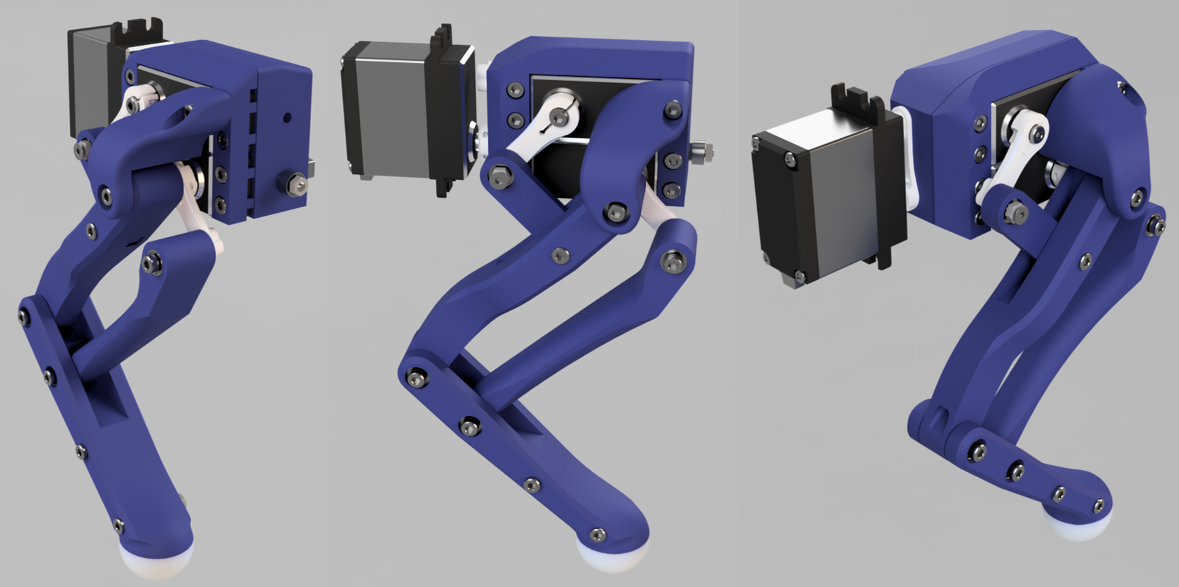
Until then, to ilustrate what is coming, here a render of the new leg.
![]()
Testings on this design have shown a quite remarkable improvement on performance.
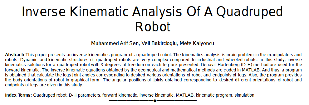
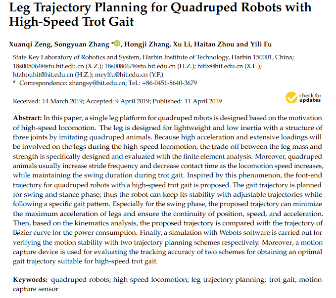
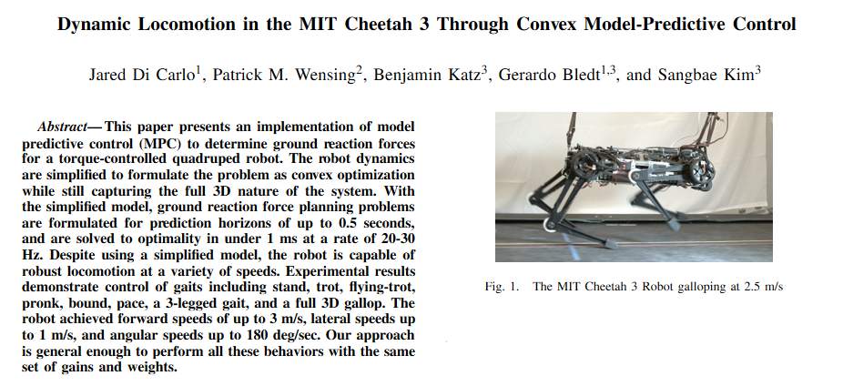
Project bibliography and interesting papers.
10/02/2020 at 13:42 • 0 commentsHere i'm going to show all the bibliography related with the project and some other reading that has inspired me.
Software documentation:
More mathematical Articles:
![]()
![]()
![]()
![]()
Small community.
09/28/2020 at 15:32 • 3 commentsThis log is just to show the repercussion of the project and say thanks for the support from all of you that are reading this project.
This is awesome to see that the hard work you made can be very useful for others. Even to the point of creating a new platform with a small community that is growing every day.
This project has let me see the values of the OPEN SOURCE community, how easy is nowadays to develop a new platform, each contributor from very different places in the word but with one commun interest that is learn things in order to make our lives more interesting.
Here are some of Makers that supported the project since the first day and they already have a small Chop at their homes:
Thanks to @OilSpigot
(min 4:00 to see his robot in action)
Thanks to @Creasento:
Bill of materials and price of the robot.
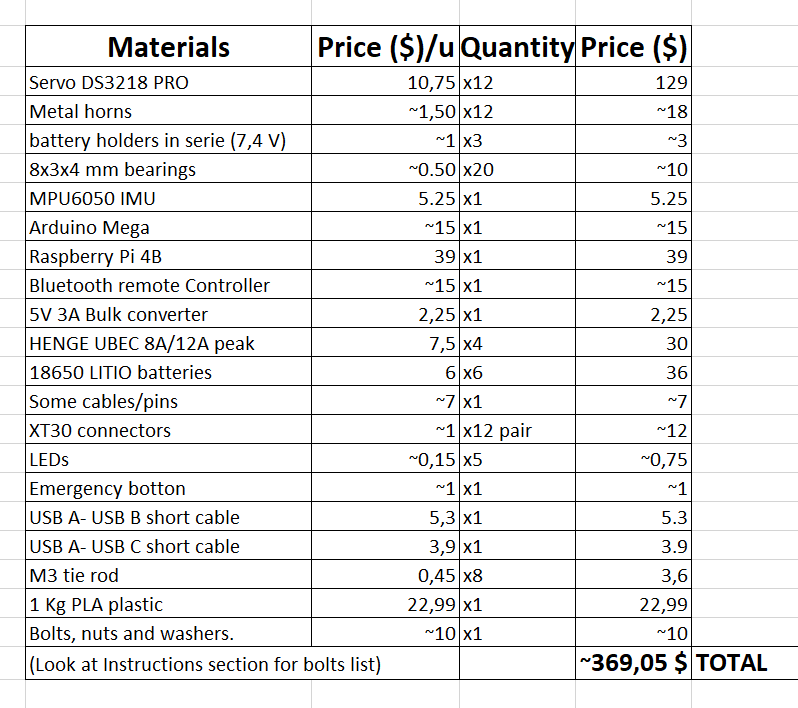
09/19/2020 at 12:33 • 0 commentsTo complete the Component Section, in this log i want to show the complete bill of materials, with the price for one unit of the robot, i have to say i'm surprised how cheap it is to build just one robot.
In my case, this development has been more expensive as i have made 3 different prototypes with its resvective components, so more or less i have spent two times the price of one unit.
![]()
Almost all componet were bought from the typical chenese online wareshops.
Once you have all the components, the building procress is not very hard if you have experience with 3D printed prototyping.
Go to Instruction Section
PyBullet Simulation example
09/15/2020 at 13:06 • 0 commentsThis log i'm going to talk about the simulation used for the robot development, this was mostly used for debugging the maths inside the the different models.
The code of the simulation is no longer implemented in the Raspberry code, as it can't support GUI mode and i'm not taking data from PyBullet environment. The code i am referring to is at the V1_PCsimulation branch of the robot GitHub repository.
This code can be ran with the robot just plugging the arduino to the PC via USB and run the robot_walking.py file, all requirements at README.mdBut if you don't have the robot built, you can run just the simulation a play along with the robot inside the PyBullet environment. Also feel free to modify it and improve it.
You just need PyBullet and Numpy on Python 3, then download the V1_PCsimulation branch and run walking_simulation_example.py.
More info of how the simulation works shown in the next video:
Now, i'm going to breightly explain the main code of the simulation, here is shown:
"""
Created on Sun Mar 15 19:51:40 2020
@author: linux-asd
"""

import pybullet as p
import numpy as np
import time
import pybullet_data
from pybullet_debuger import pybulletDebug
from kinematic_model import robotKinematics
from gaitPlanner import trotGait

"""Connect to rhe physics client, you can choose GUI or DIRECT mode"""
physicsClient = p.connect(p.GUI)#or p.DIRECT for non-graphical version
p.setAdditionalSearchPath(pybullet_data.getDataPath()) #optionally
"""set Gravity"""
p.setGravity(0,0,-9.8)

"""import the robot's URDF file, if it is fixed no ground plane is needed"""
cubeStartPos = [0,0,0.2]
FixedBase = False #if fixed no plane is imported
if (FixedBase == False):
    p.loadURDF("plane.urdf")
boxId = p.loadURDF("4leggedRobot.urdf",cubeStartPos, useFixedBase=FixedBase)

jointIds = []
paramIds = []
time.sleep(0.5)
"""get info along all the joints for debugging if needed"""
for j in range(p.getNumJoints(boxId)):
#    p.changeDynamics(boxId, j, linearDamping=0, angularDamping=0)
    info = p.getJointInfo(boxId, j)
    print(info)
    jointName = info[1]
    jointType = info[2]
    jointIds.append(j)

footFR_index = 3
footFL_index = 7
footBR_index = 11
footBL_index = 15

"""init the classes used"""
pybulletDebug = pybulletDebug()
robotKinematics = robotKinematics()
trot = trotGait()

#robot properties
"""initial foot position"""
#foot separation (Ydist = 0.16 -> tetta=0) and distance to floor
Xdist = 0.20
Ydist = 0.15
height = 0.15
"""This matrix will define where the feet are going to be at its standing position
with respect the center of the robot"""
#body frame to foot frame vector
bodytoFeet0 = np.matrix([[ Xdist/2 , -Ydist/2 , -height],
                         [ Xdist/2 ,  Ydist/2 , -height],
                         [-Xdist/2 , -Ydist/2 , -height],
                         [-Xdist/2 ,  Ydist/2 , -height]])
"""Gait definition parameters, here you can set different period of step and
the offset between every foot's loop, defining different gaits"""
T = 0.5 #period of time (in seconds) of every step
offset = np.array([0.5 , 0. , 0. , 0.5]) #defines the offset between each foot step in this order (FR,FL,BR,BL)

"""start a real time simulation, so no simulation steps are needed"""
p.setRealTimeSimulation(1)

while(True):
    lastTime = time.time()
"""show sliders in the GUI"""
    pos , orn , L , angle , Lrot , T = pybulletDebug.cam_and_robotstates(boxId)
    #calculates the feet coord for gait, defining length of the step and direction (0º -> forward; 180º -> backward)
    bodytoFeet = trot.loop(L , angle , Lrot , T , offset , bodytoFeet0)

#####################################################################################
#####   kinematics Model: Input body orientation, deviation and foot position    ####
#####   and get the angles, neccesary to reach that position, for every joint    ####
    FR_angles, FL_angles, BR_angles, BL_angles , transformedBodytoFeet = robotKinematics.solve(orn , pos , bodytoFeet)

"""move all joints at the next time step angle"""
    #move movable joints
    for i in range(0, footFR_index):
        p.setJointMotorControl2(boxId, i, p.POSITION_CONTROL, FR_angles[i - footFR_index])
    for i in range(footFR_index + 1, footFL_index):
        p.setJointMotorControl2(boxId, i, p.POSITION_CONTROL, FL_angles[i - footFL_index])
    for i in range(footFL_index + 1, footBR_index):
        p.setJointMotorControl2(boxId, i, p.POSITION_CONTROL, BR_angles[i - footBR_index])
    for i in range(footBR_index + 1, footBL_index):
        p.setJointMotorControl2(boxId, i, p.POSITION_CONTROL, BL_angles[i - footBL_index])

#    print(time.time() - lastTime)
p.disconnect()
Future 3DoF foot sensor.
08/27/2020 at 20:52 • 0 commentsIn order to make the robot dynamic in the precisse meaning of the word, we need to have meassurements of the forces acting acting inside the robot, this can be either from the actuators, feet or the IMU.
This way we can build a robust control algorithm taking into account these forces, such as the Inverse Pendulum model. Basically what we want in here is to implement a physics math model in stead of a direct model like the Kinematics model it implements now.
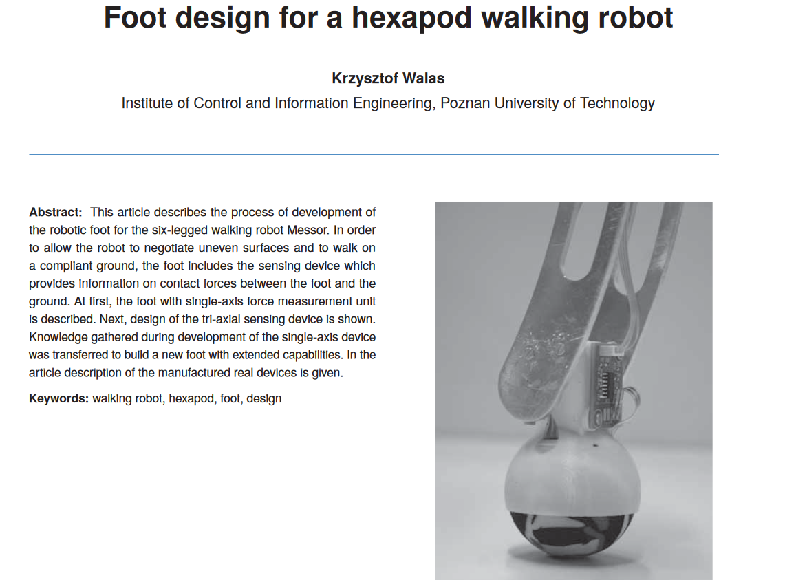
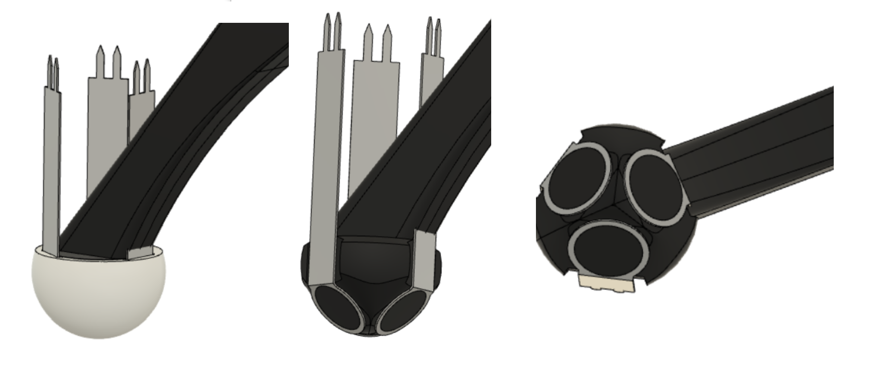
This task is not easy to achive, but i found a paper with a very inteligent solution to this problem: Foot design for a hexapod walking robot.
Basically it uses 3 sensitive resistance force sensor, with a proper orientation in order to read the forces at the foot in the 3 different directions.
What i came with is shown in this pictures, but this is only a quick design with lot of errors at the time of reading accurate meassurements.
![]()
Some actual works on the MIT cheetah show how usefull can be this type of foot sensor:Calibrating the servos.
08/01/2020 at 09:15 • 0 commentsFirst of all, you will need to plug all servos to their proper pin, in my case here they are (you can change this for your how setup):
void connectServos() {
                      //FR
  Servos[0].attach(40); //coxa
  Servos[1].attach(38); //femur
  Servos[2].attach(36); //tibia
                      //FL
  Servos[3].attach(42); //coxa
  Servos[4].attach(44); //femur
  Servos[5].attach(46); //tibia
                     //BR
  Servos[6].attach(34); //coxa
  Servos[7].attach(32); //femur
  Servos[8].attach(30); //tibia
                     //BL
  Servos[9].attach(48); //coxa
  Servos[10].attach(50); //femur
  Servos[11].attach(52); //tibia
}
As soon as the servos are corretly attached, what i made in order to put the servos on its correct position is just to dissasembly the legs, i mean, separate the servo output from the its horn, in order to let the servo move freely. This way you can power the servos, let them go to the zero position and the reassembly.
I wrote a small sketch in order to put the servos on their zero position, you can find it at servo_calibration.py file, this way you can attatch the servo very close to their zero position.
Then, a more precise calibration is needed, you will need to calibrate the offset of each servo, those offset are defined at angleToPulse.py file. This file only contains the line defining the pulse corresponding to each angle for every servo.
Being a line in the form: y = Ax + B. The offset of each servo is defined by B, which mean the pulse at the zero angle.
If you are using different servos, the slope of the line (A) will be different so you will need to identify it. What i did, is just to take 4-5 meassurement of pulse at different angles and put them on an excel where i calculate the adjucted line from those points.
def convert(FR_angles, FL_angles, BR_angles, BL_angles):
    pulse = np.empty([12])
    #FR
    pulse[0] = int(-10.822 * np.rad2deg(-FR_angles[0])) + 950
    pulse[1] = int(-10.822 * np.rad2deg(FR_angles[1])) + 2280
    pulse[2] = int(10.822 * (np.rad2deg(FR_angles[2]) + 90)) + 1000
    #FL
    pulse[3] = int(10.822 * np.rad2deg(FL_angles[0])) + 1020
    pulse[4] = int(10.822 * np.rad2deg(FL_angles[1])) + 570
    pulse[5] = int(-10.822 * (np.rad2deg(FL_angles[2]) + 90)) + 1150
    #BR
    pulse[6] = int(10.822 * np.rad2deg(-BR_angles[0])) + 1060
    pulse[7] = int(-10.822 * np.rad2deg(BR_angles[1])) + 2335
    pulse[8] = int(10.822 * (np.rad2deg(BR_angles[2]) + 90)) + 1200
    #BL
    pulse[9] = int(-10.822 * np.rad2deg(BL_angles[0])) + 890
    pulse[10] = int(10.822 * np.rad2deg(BL_angles[1])) + 710
    pulse[11] = int(-10.822 * (np.rad2deg(BL_angles[2]) + 90)) + 1050
    return pulse
A more stable walking.
07/20/2020 at 11:49 • 0 commentsThis log is about polishing the gaitPlanner as you can see in the next video:
What is interesting on this video is that no control algorithm is running, but it seems very stable.
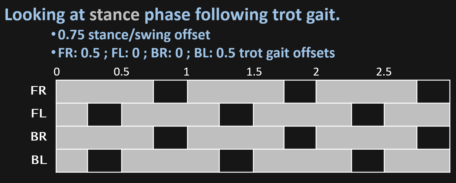
This is achived just by separating stance phase from the swing (as explained in the gaitPlanner.py log), this way i can define an offset between both phases, so running the stance phase at 3/4 of the hole step, makes the robot to hold its weigth on the 4 legs for a short period of time being a bit more stable, just by running the gaitPlanner loop.
Visually the gait is defined like follows:![]()
Aditional info about that is that servos got very hot if it runs for more than 10 minutes.
Quadruped robot meets my cat.
07/07/2020 at 18:29 • 0 commentsAs a quick update of the V2 robot performing i have introduced it to my cat.
My cat is very introverted and usually doesn't like new things, in this case isn't different but it seems to cause she some curiosity.
The robot performs well, as it uses the last version of the code, the extra weigth of the batteries and raspberry pi is not a problem as the new design is much more lighter and the servos are now powered at 6V in stead of 5V as in the first version.
On the other hand, i have notice the model randomly gives bad solutions running on the raspberry pi, thats why sometimes you see the leg make a strange movement. I haven't identify the problem yet, maybe is my software problem or bufer overflow.
There is no aim to hurt the animal, is my cat omg.
DIY hobby servos quadruped robot
Cheap 3D printed 4 legged robot, that almost looks like boston dynamics spot but moves like a newborn.
 Miguel Ayuso Parrilla