 Lucas
Lucas-
1Building the battery
As the battery is defintely the most important component of an electric transportation medium, I wanted to create my own to use high end materials and keep the cost low. With 20 Sony VTC6 cells and a BMS you can have a 200Wh (10S2P) batery for just over 105$ !
You will need a spot welder like this one or simply solder copper wires with a soldering iron.
You'll find on internet plenty of videos to build you own lithium battery so I will simply focus on the specifics of the shape here to have a battery that fits our case for a foldable board.
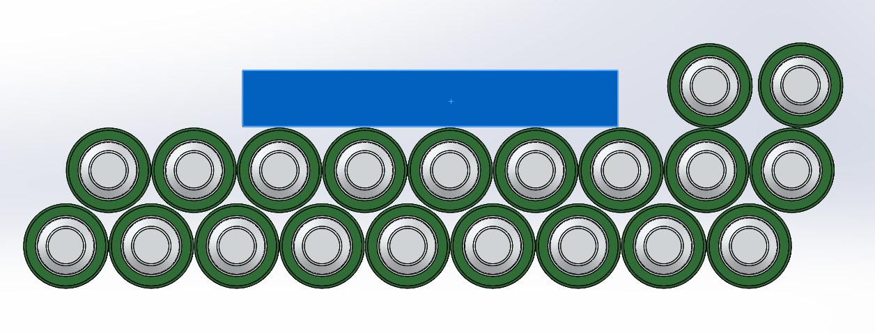
The battery and its BMS will have the following pattern to fit with the casing :
![]()
I would recommand to sold the batteries 2by2 in parallel (as this battery will be a 10S 2P)![]()
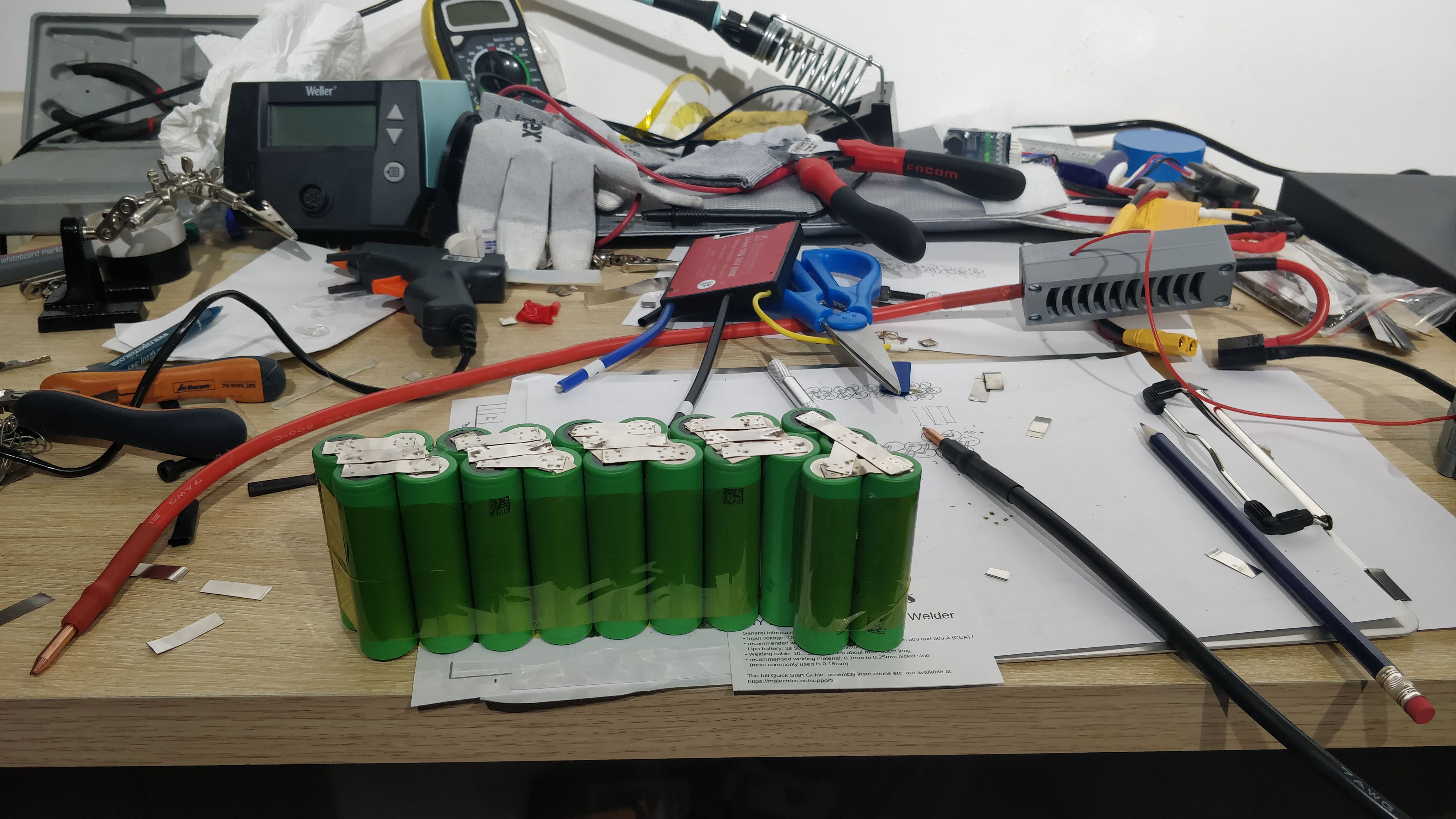
Then assemble the 10 bi-cells together. I used 3 layers of 7mmx0.15 nickel strip but 10mmx0.15 strips would be even better for 0 heating of the connections.![]()
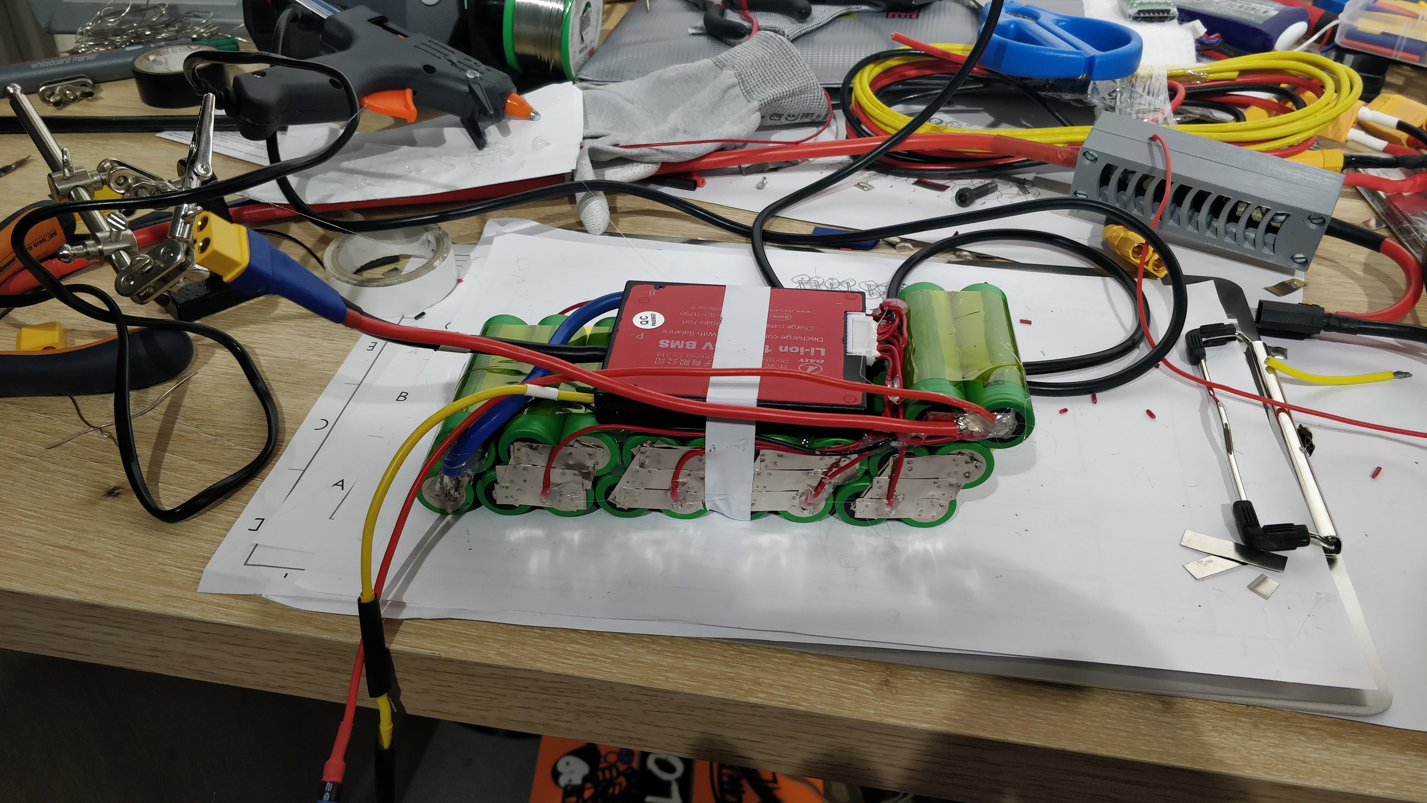
And finally solder the power cable as weel as the balancing wires :
![]()
Here we are with a high-end custome shaped battery ! :)
I've padded it with some plastic cushion and electric tape ; I'am waiting to receive a battery sleeve heatshrink to hide all this mess in a more professionnal looking packaging ;)
-
2Assembling the skate
Most of the components are available on the shelf with the link provided in the build list.
You will also have to print the case and its cover (I printed it on Cura, with support, 20% infill). Black and white for the style...unfortunately, the chinees ebay retailer for the wheel choosed to send me the wrong tyre color for the idle wheel... The printable file and orignals are available in the files folder.
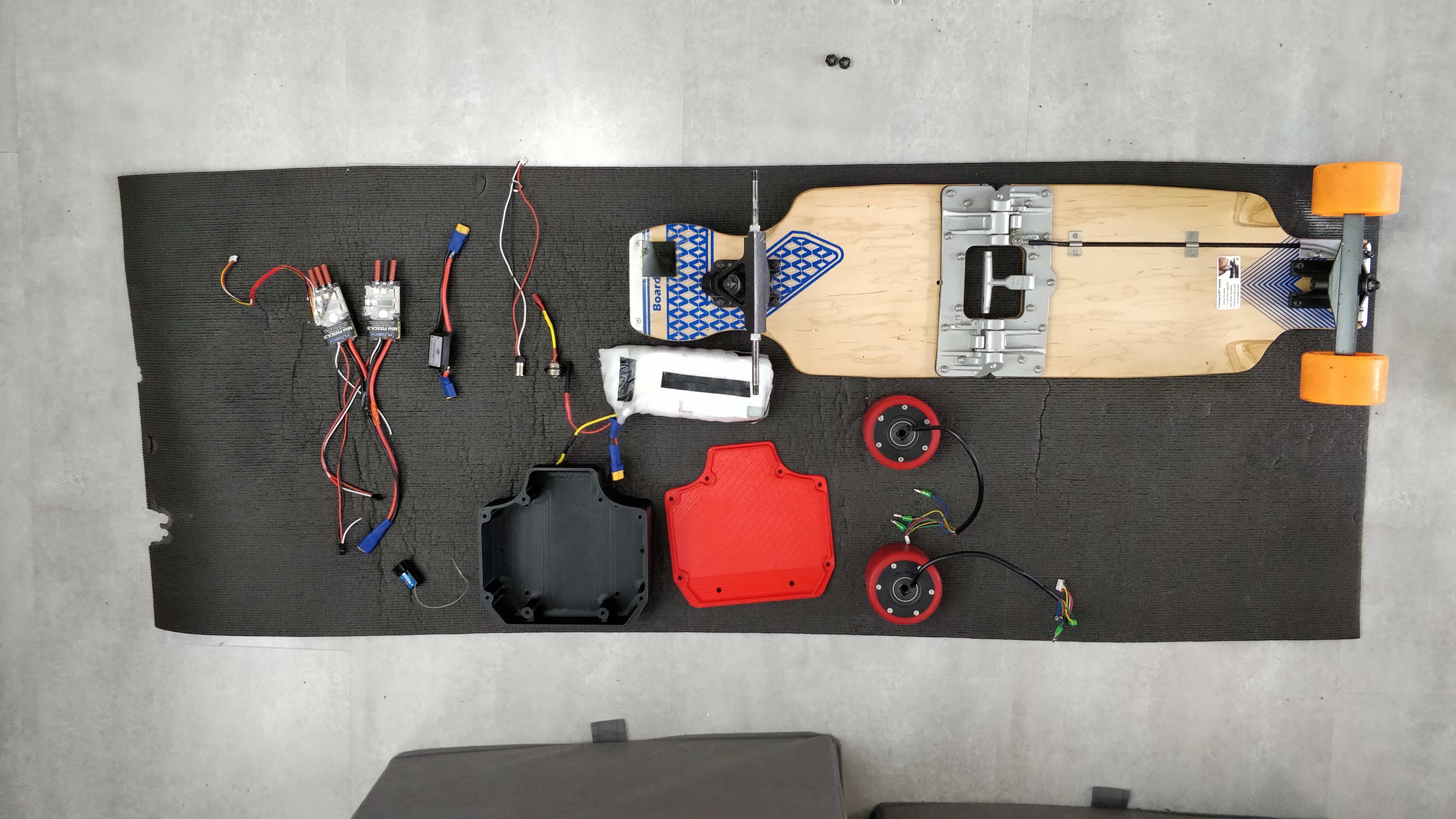
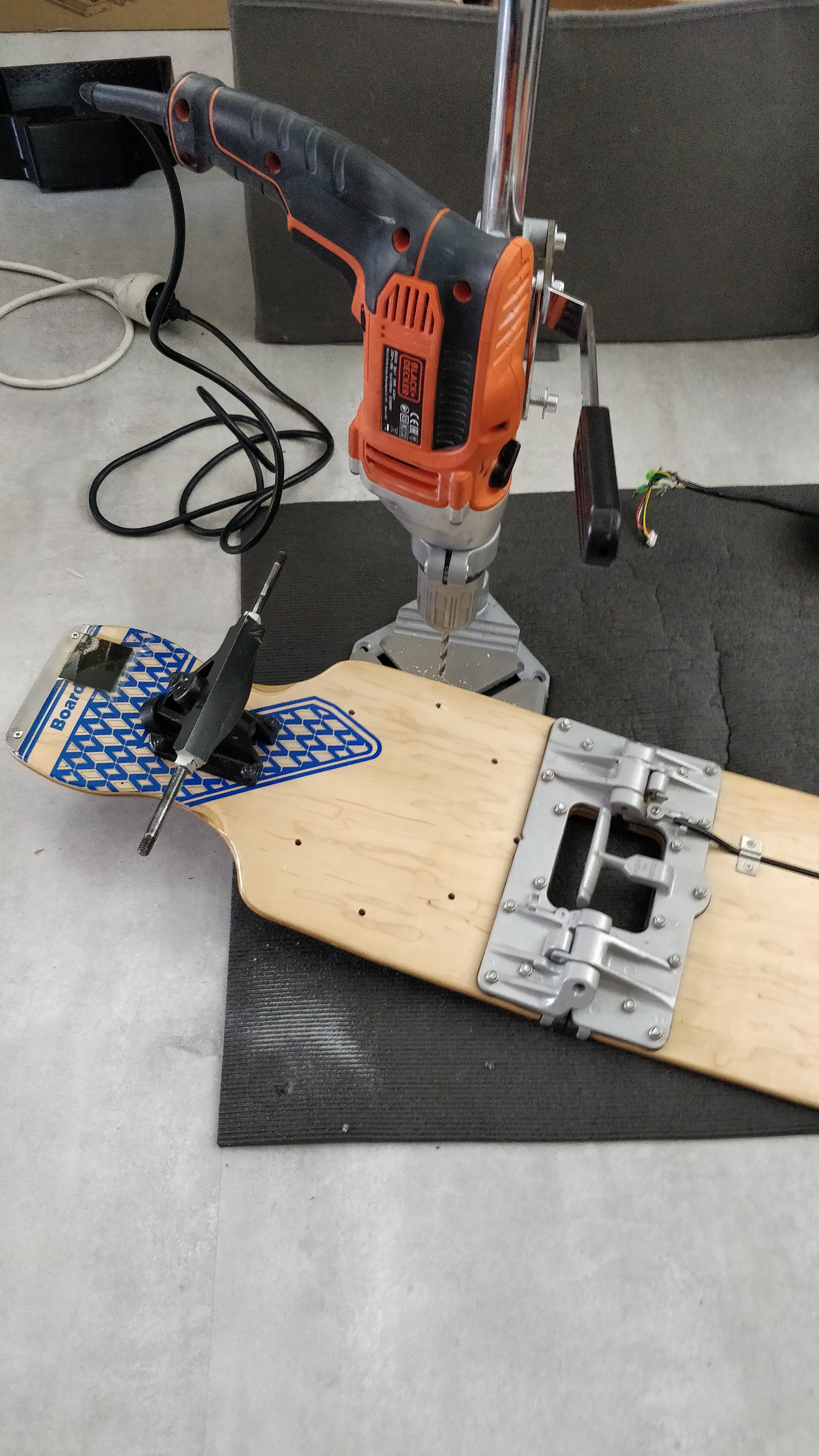
You've gathered all the components from the BoM ? So they should look like that (with a little bit of soldering work). Ready for the assembly ?
![]()
Next step will be to mount the case on the deck. Feel free to drill 6 holes according to the cover pattern and add a spotface for the countersunk head screws.
![]()
Mount the case as well as the charging plug and power button.![]()
Vibrations are nasty on sketoboards so use self-locking nuts!!
Finally mount the trucks and the hub motors. -
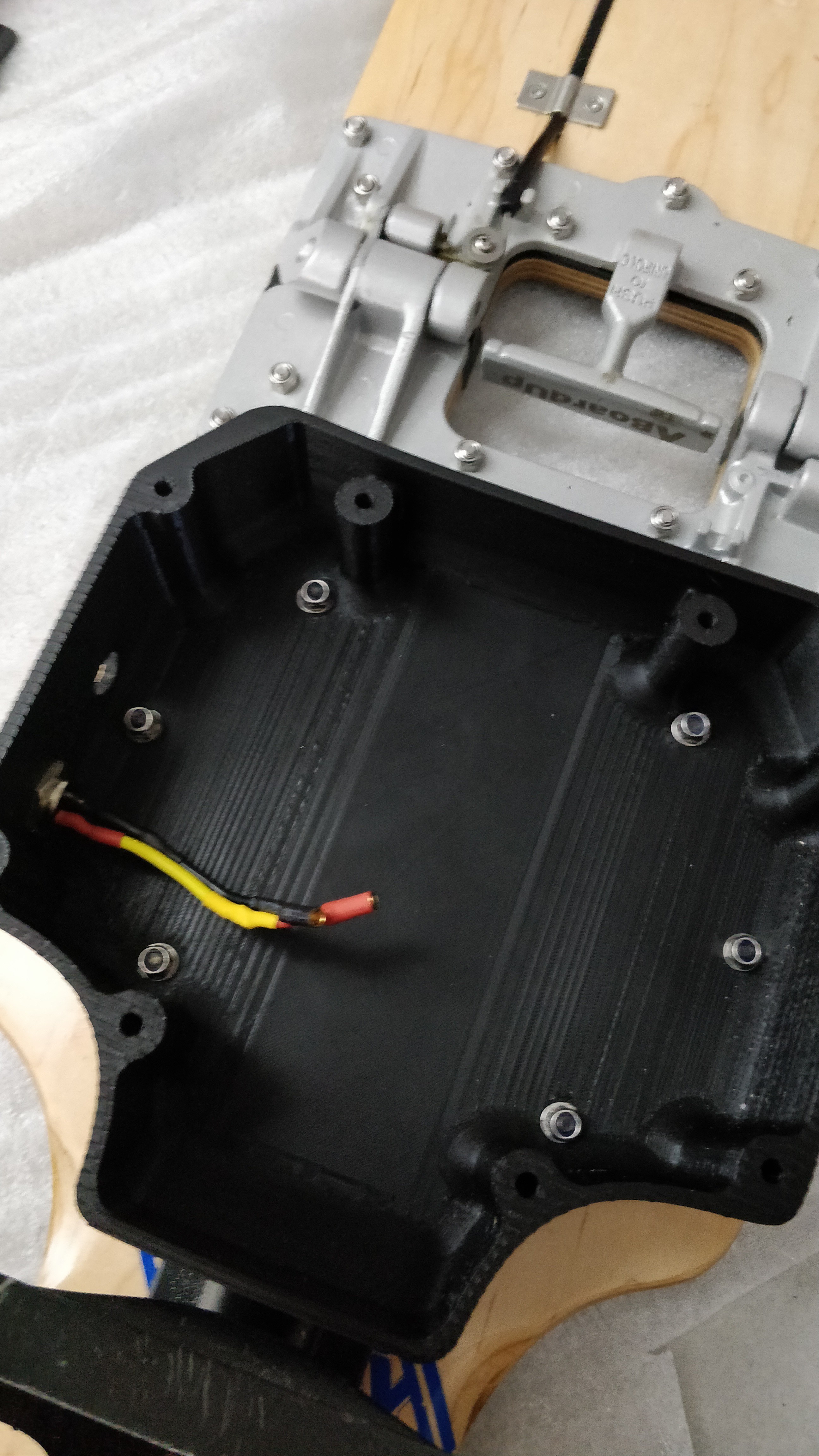
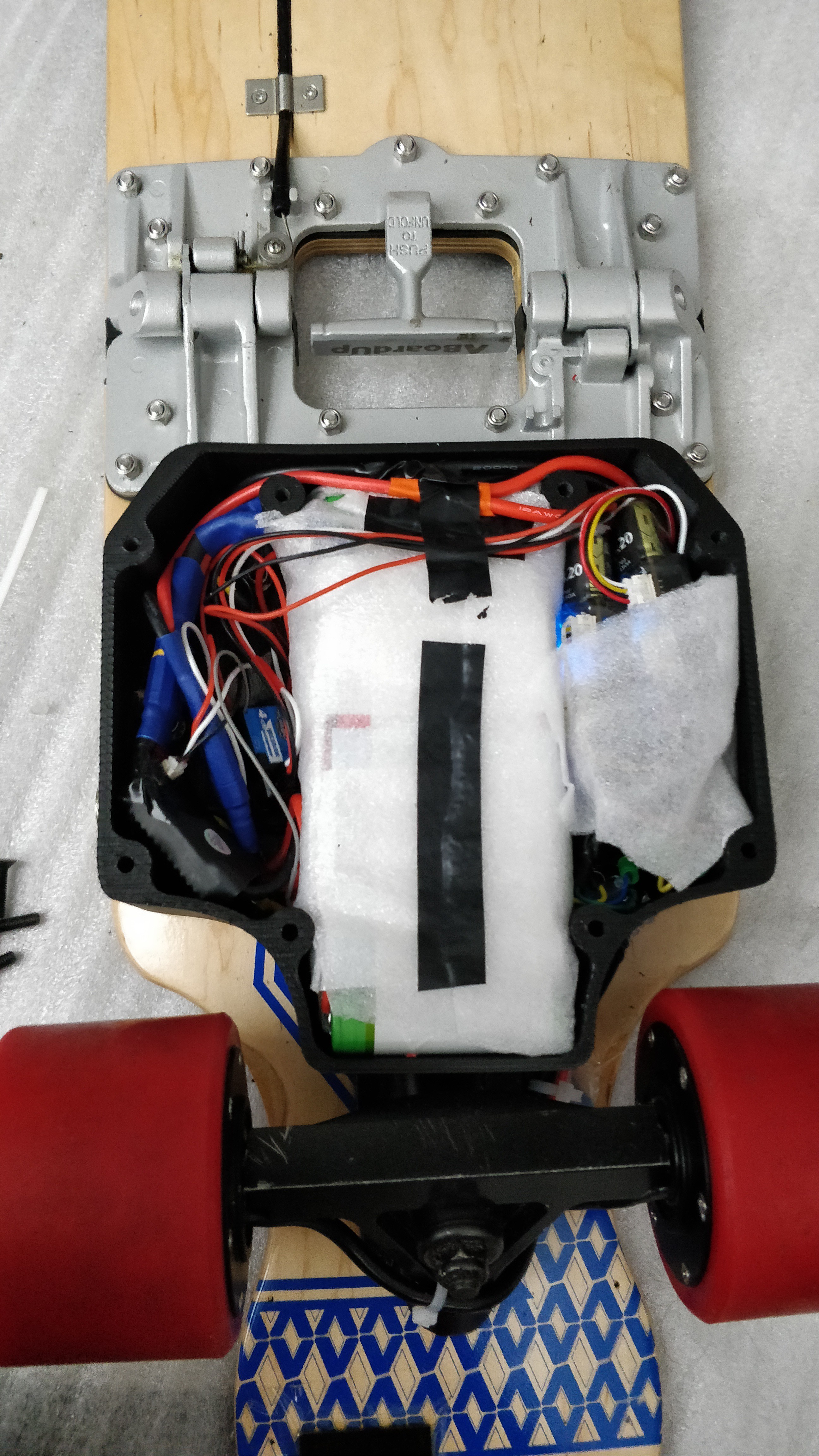
3Stuff in the electronics
![]()
The case dimensions are not fully optimized, to gibe some slack on the wiring and allow some heat sink. So feel free to pad with cushion here and there and snug in the electrnics.
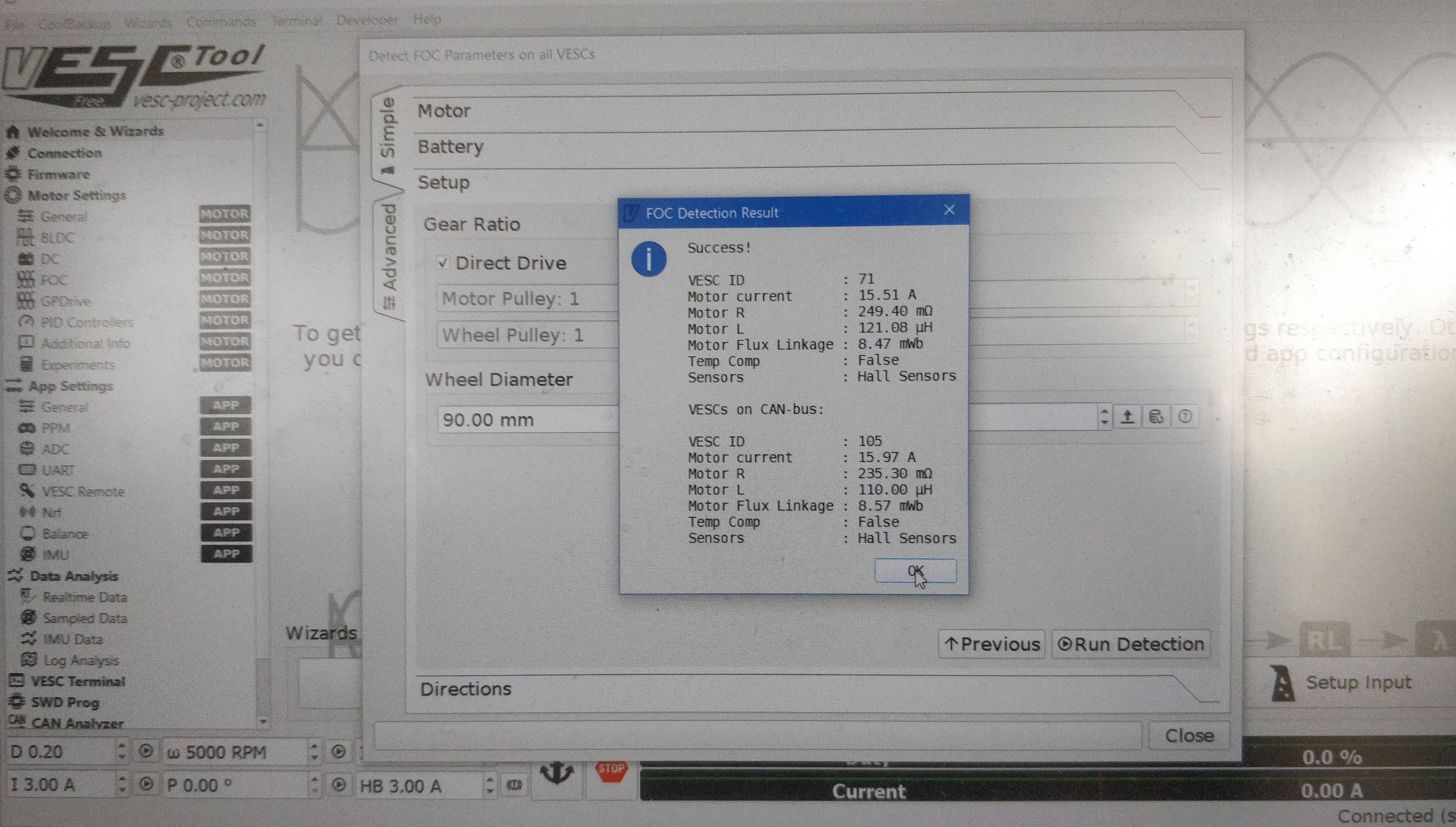
You can then configure your VESCs. Here are my motor parameters :
![]()
-
4Configuring Bluetooth module for wireless configuration and logging in VESC 4.12
Benjamin Vedder added some neat little features in its latest release. In particular, you can connect a 4$ Bluetooth chip to the UART port to replace USB connection. Thus, you can remotely connect to the VESC from a BT laptop or an android phone, change settings and follow indicators in real time !
Althouth the instruction are not really clear so here are a few instructions to setup a bluetooth connection with VESC on your phone.
It currently works with firmware 5.1 on HW 410 (Vesc 4.12).
Purchase one of the NRF 51822 modules :
Also, you will need a ST-Link V2 module
It exists in 4 : a 32Mhz and 16Mhz quartz version each with 2 ram size (16k and 32k). VESC code is compatible with the 4 versions.
From my understanding, quartz frequency is not important. To use your chip as a bluetooth gateway for wireless settings and logging, 16k ram should be fine ; but if you plan to use also a bluetooth remote and advanced remote features, you should take a 32k ram.
You will find extra discussions about the module here : https://vesc-project.com/node/234?page=1
When receiving the bluetooth module, you’ll need to flash it. You can find pre-compiled files here : https://github.com/vedderb/nrf51_vesc/tree/master/build_all
Choose the version according to your chip (for the link above: nrf51_vesc_ble_16k_16m_rx1_tx2_led3.bin )
To be noted that Benjamin Vedder’s code offer two options for the RX and TX pins. Either use the P01&P02 or P09&P11. I chose to connect the pins 1 and 2 for RX and TX but you could also choose to connect the pin 9 and 11 with the according bin file).
Then wire SDO, SCL, 3,3V and GND pins from the NRF51822 to your ST-Link 32
Hera is a picture of the NRF51822 wired for flashing and communication to the VESC in the same time.
Install OpenOCD and launch a windows terminal (push the keys Win+R and type cmd ), then navigate to your OpenOCD install folder (using the commands cd) .
Copy/paste there the *.bin file as well as the openocf.cfg and launch the following command :
openocd -f openocd.cfg -c "init" -c "halt" -c "nrf51 mass_erase" -c "program nrf51_vesc_ble_16k_16m_rx1_tx2_led3.bin verify reset exit"
You should have this on the screen :
xPack OpenOCD, 64-bit Open On-Chip Debugger 0.10.0+dev (2019-07-17-11:28) Licensed under GNU GPL v2
For bug reports, read http://openocd.org/doc/doxygen/bugs.html WARNING: interface/stlink-v2.cfg is deprecated, please switch to interface/stlink.cfg
Info : The selected transport took over low-level target control. The results might differ compared to plain JTAG/SWD Info : clock speed 1000 kHz Info : STLINK V2J36S7 (API v2) VID:PID 0483:3748
Info : Target voltage: 3.195303
Info : nrf51.cpu: hardware has 4 breakpoints, 2 watchpoints
Info : Listening on port 3333 for gdb connections target halted due to debug-request, current mode: Handler SVCall xPSR: 0x4100000b pc: 0x00009198 msp: 0x20003ea8
Warn : Unknown device (HWID 0x00000138) target halted due to debug-request, current mode: Thread xPSR: 0xc1000000 pc: 0xfffffffe msp: 0xfffffffc ** Programming Started ** Warn : using fast async flash loader. This is currently supported Warn : only with ST-Link and CMSIS-DAP. If you have issues, add Warn : "set WORKAREASIZE 0" before sourcing nrf51.cfg/nrf52.cfg to disable it ** Programming Finished **
** Verify Started **
** Verified OK **
** Resetting Target **
shutdown command invoked
Otherwise you have an issue in wiring or a defective chip.
Once done, just solder the pins P01, P02 (or P09&P11), GND and VDD and connect them to the VESC on the UART connector (VDD should go on the 3,3v). P01 should be connected to TX and P02 to RX (or P09 should be connected to TX and P11 to RX).
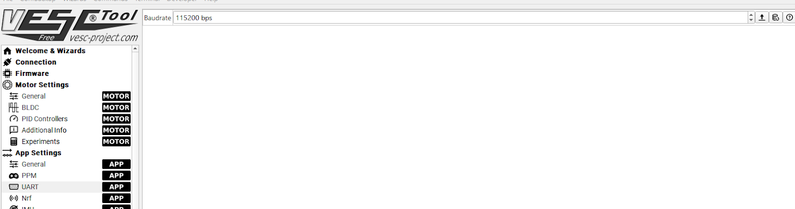
Finally, to get a connection ; connect a last time via USB to the VESC and in the App Settings > General, Select “PPM and UART” for the AppToUse parameter .
Also, make sure that the baud rate is 115200 bps in the UART tab.
From now on you can access to your VESC by bluetooth.
Also, if you wire your 2 VESCs together through a CAN cable (2wire cable on the CAN port) ; you will be able to control andtweak the 2 VESC from this only Bluetotth entry point.
Super neat!
Enjooooooy !
Le-Sk8te - Foldable electric longboard
Electric foldable longboard for micro-mobility and commuting


Discussions
Become a Hackaday.io Member
Create an account to leave a comment. Already have an account? Log In.