-
Rev 1.1 of the Microphone Fanout Board Arrived
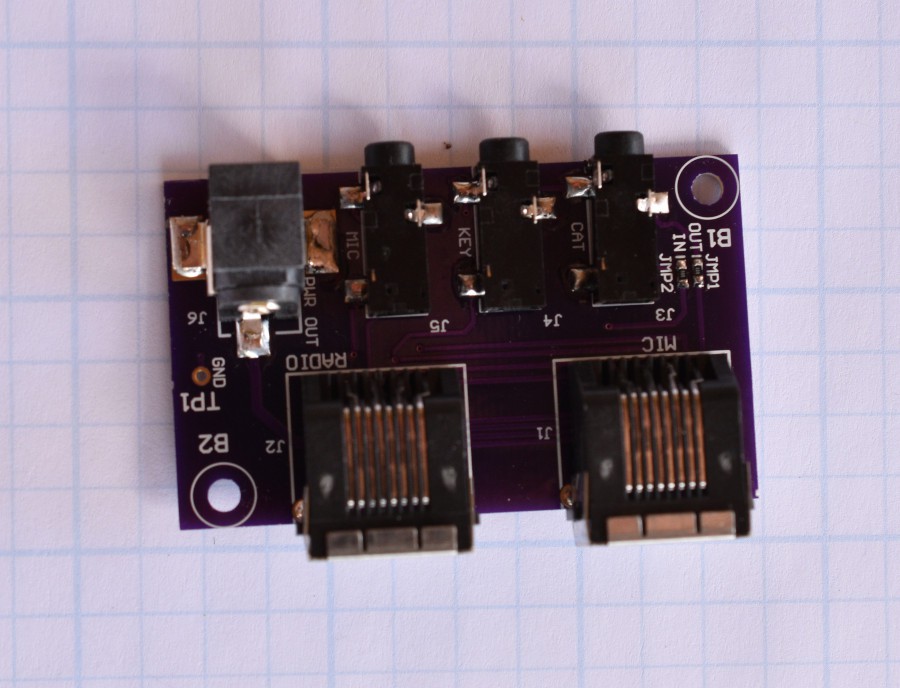
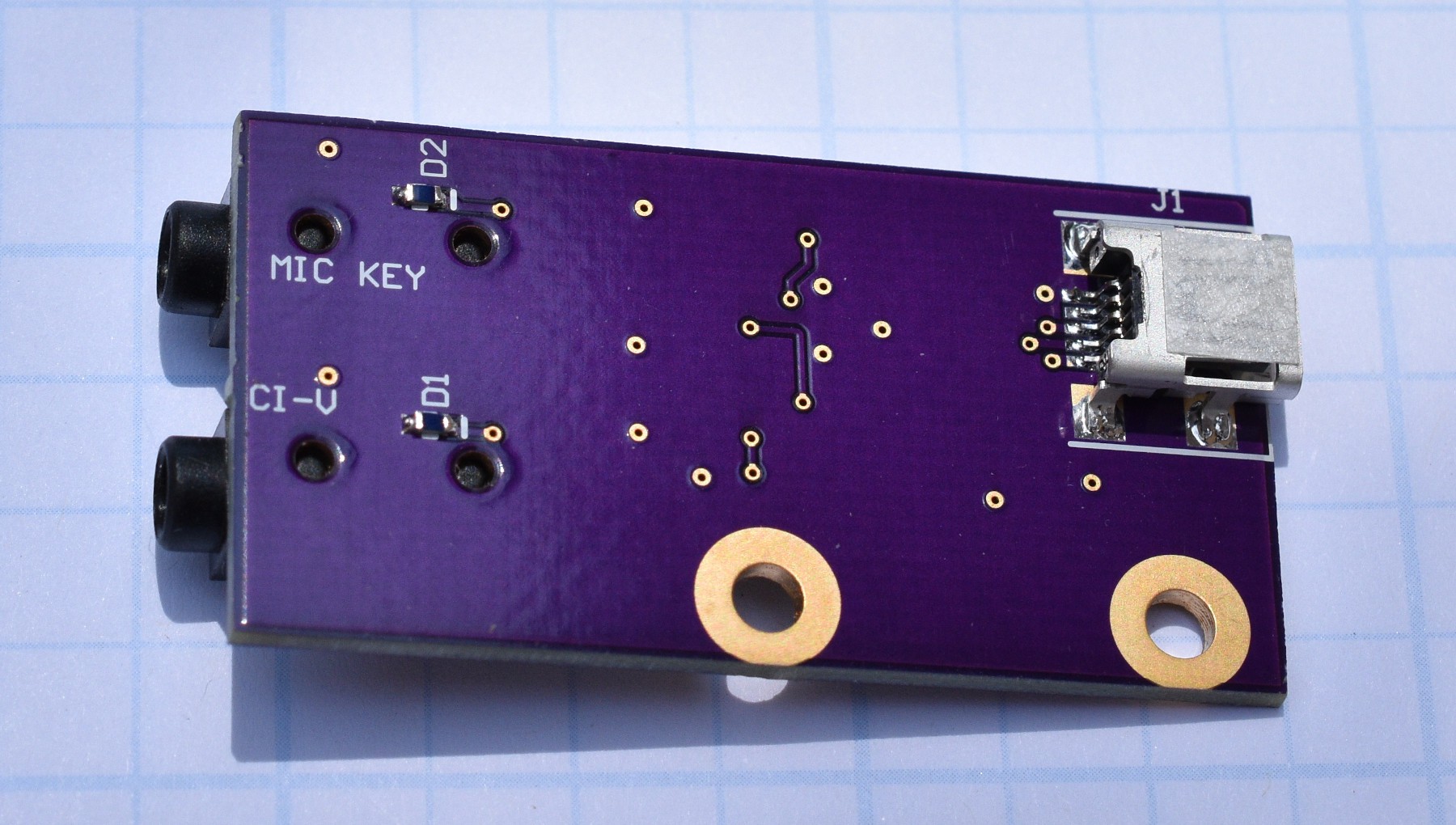
07/06/2020 at 22:52 • 0 commentsThe revised microphone fanout board for the Yaesu 857D radio arrived today. This one was designed from the schematic that shipped with my radio. All of the wierdness is gone with the interface. I can control the 857D radio via the Hamlib rigctl tool and read data back as well. This means that my USB to CAT/CI-V interface boards that have optional half or full duplex via a jumper are working too!
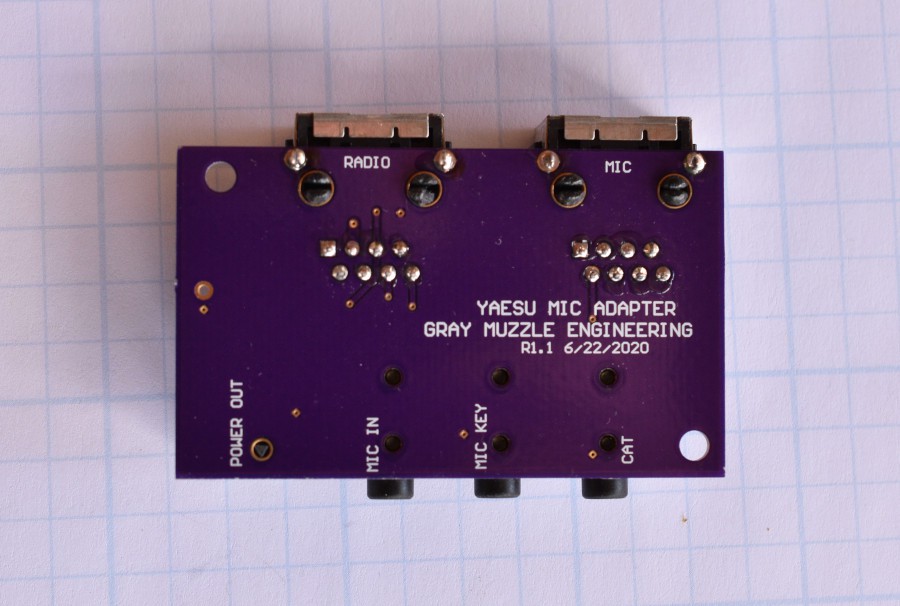
This is the built up fanout board. All of the connectors were re-used from the original, messed up board.
Removing the surface mount components is quite easy. I put the old board on top of my re-flow hot plate and turned the heat up a little, and then picked up the free connectors with a pair of tweezers. The RJ45 through hole connectors were a little messier, requiring a pair of pliers to pull off the board.
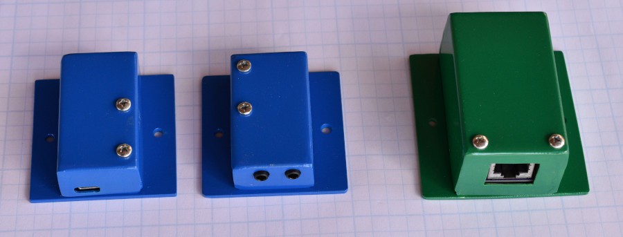
Cleaning up another semi-related project, I got tired of handling a bare PCB whenever I went to use it. The USB to CAT/CI-V boards are pretty small and I wanted some protection for them, so I designed and fabricated enclosures for them. Now they are all powder coated and looking clean. The only thing missing are labels for the boxes.
Here are two of the USB to CAT/CI-V boards in their new enclosures. The green box is the 2 channel RS232 to RJ45 project that motivated me to make the other enclosures. It is used to control the satellite antenna rotator.
The tops of the enclosures were folded up from 0.030" 5051 aluminum and the baseplates are 0.090" 6061 aluminum. Figuring out how to transfer the dimensional data out of my PCB CAD system into the mechanical drawing CAD system has been interesting. I think that process needs some more work.
-
Problems Testing the Yaesu 857D Setup
06/23/2020 at 22:49 • 0 commentsIn order to simplify cabling and make the installation cleaner, I laid out a PCB that goes between the handheld microphone and the radio. It has a pair of RJ45 connectors on it and connectors for the CAT data, Mic Key, Mic input, and DC power out (+5V). I dug up a Yaesu service manual from the web and proceeded to design the board from the connector documentation shown in the schematics. The boards came back a while later and I went to test them yesterday. The voltages on several pins were showing negative 5V and weird things happened when I connected the computer.
The schematic that shipped with the radio was handy when I got the radio out of it's box, and it turns out that the signal naming on my board was flipped according to the schematic that shipped with the radio. Hoping that I had not screwed up that severely, I compared the schematic from the service manual to the one that shipped with the radio. The schematic in the service manual had the signal naming reversed! From the voltages and behavior, I believe it is reversed. I was not expecting a discrepancy of that severity! When I laid out the board, I poured copper across all of the bottom side of the board to tie the grounds together. The cutting and abuse needed to blue wire this board for testing is just too much. I corrected the schematic and then the PCB and sent it out for fabrication. The bare boards are not terribly expensive ($16US) but it adds a couple of weeks to finishing this project.
I did build up the modified USB to CI-V/CAT board that came back at the same time, and it works fine talking to the ICOM 756 that I have been using to play with FT8.
-
Connecting to a Yaesu Radio
05/30/2020 at 19:09 • 0 commentsI was looking at doucmentation to hook up to a couple of different Yaesu radios. The FT60 handitalkie should connect to the boards without an issue, it uses one wire (and ground) to talk to the radio. The 857D mobile is a different beast. It has separate RxD and TxD lines. The open collector scheme looks valid still.
Rather than pursue a separate PCB, I added a jumper and a couple of passives to allow the board to work in either configuration. The USB interfaced board design has been modified to verify operation with both configurations. When that is working correctly, I will update schematics and update the other boards. The 3.5mm jacks that were used on these boards are stereo jacks. In the existing board design and the "2 wire" jumper configuration, the data in and out are on the tip of the plug and the ring is left unconnected. In the "3 wire" configuration on the new board, the tip is the TX data out and the ring is the RX data in. The body of the connector in all configurations is ground.
When the new boards come back from OSH Park and I can test them, I will post the new schematics. The existing schematics work fine for talking to any radio that only uses a single data wire.
-
Revised PCBs back
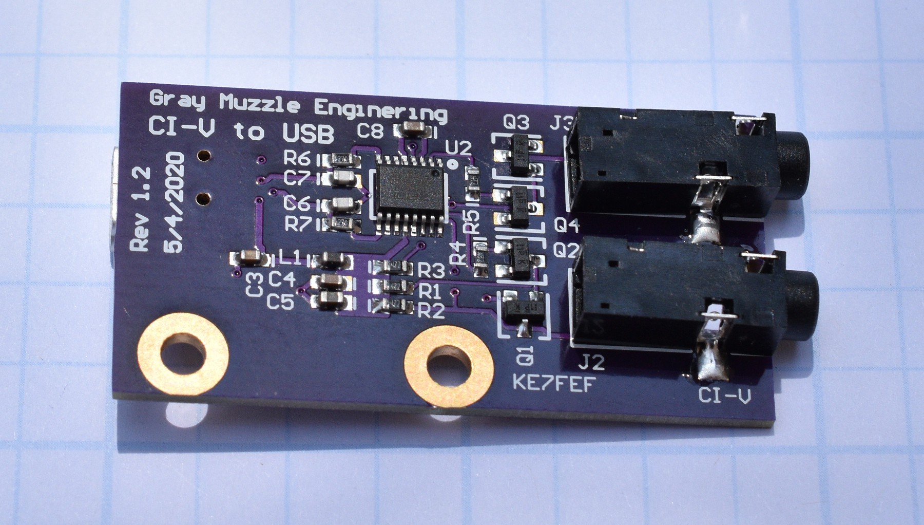
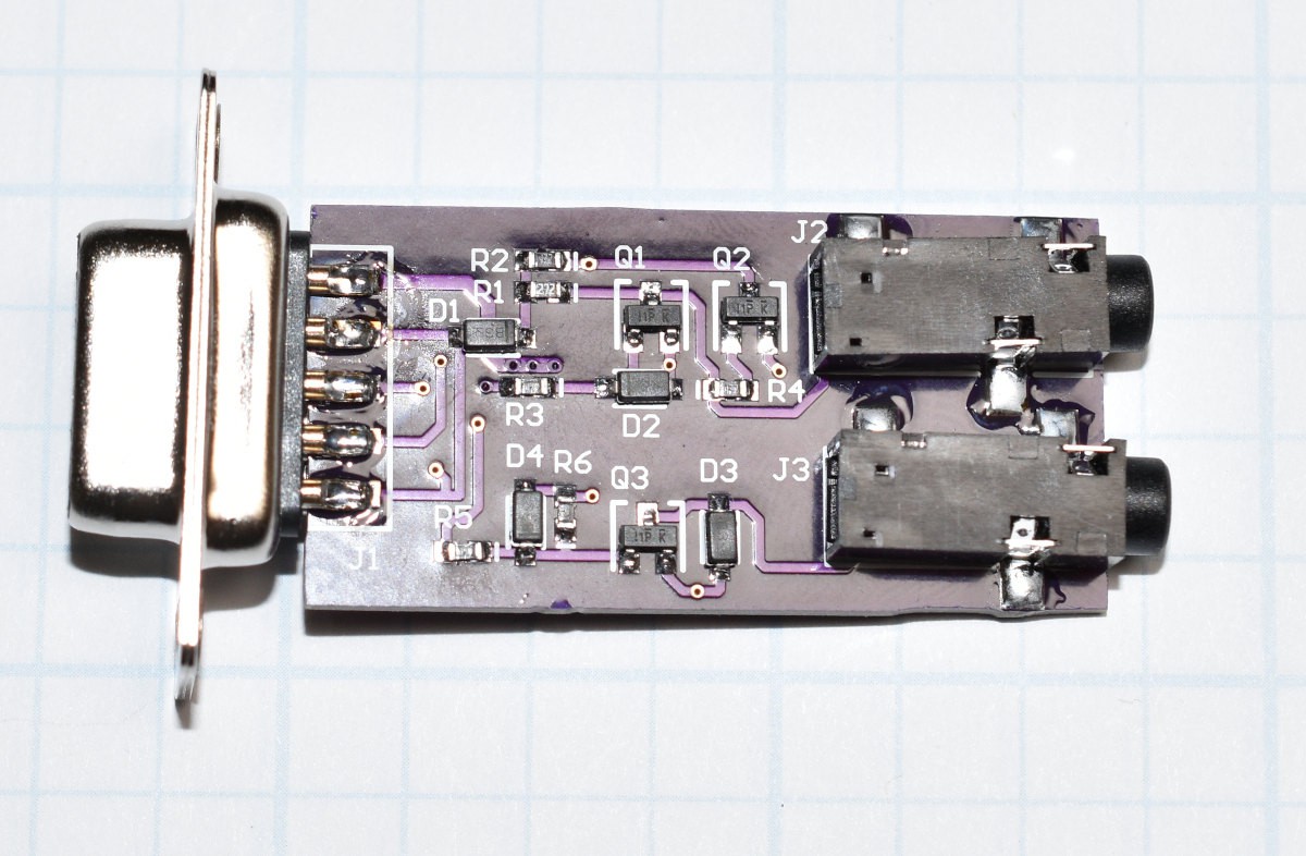
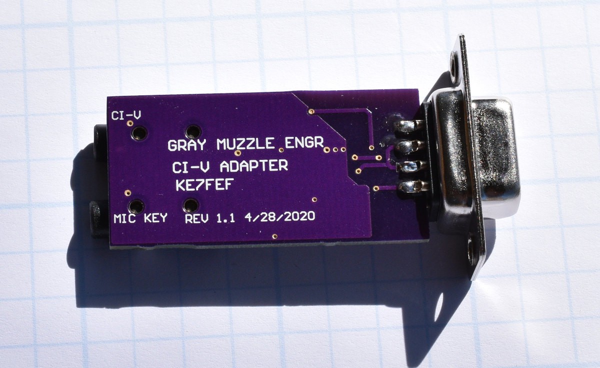
05/17/2020 at 17:39 • 0 commentsThe revised PCBs for both the RS232 to CI-V and the USB to CI-V units came in on Friday. Revision 1.1 of the USB board just had the wiring error fixed and never got sent to fabrication. Revision 1.2 is rip up and re-do on the component placement from revision 1.0 of on the USB board. On the initial PCB, the USB data + and - lines had to cross between the connector and the chip. Orientation of the chip did not work well with either the USB connections. The two 3.5mm jacks were close enough together that it was marginal to plug both in simultaneously. On Rev 1.2, the USB connector got moved to the back side of the board and the chip got rotated 90 degrees. Spacing between the 3.5mm jacks got increased. The rest of the components got re-distributed to work with those changes. Board size remained the same. The wiring error on the 3.5mm jack got corrected as well. I am not a big fan of connectors on the back side of a PCB, but it was the best choice with the connectors that I have. The new layout is much cleaner. Building the Rev 1.2 board went quickly, even with hand soldering the SMT USB connector to the back side of the board.
I swapped the Rev 1.2 board for the 1.0 board on my FT8 setup this morning and it works fine.
If anybody is interested in building one (or 3) of these boards, message me and I will send you the artwork. If people are interested, I will share the artwork on OSH Park. A run of 3 boards costs about $9.60US and the components to populate a board are about $10US for one board.
I was planning to wait to build the revision 1.1 of the RS232 board, but the externally powered version PCBs will not be here until late this week and I got bored.
The only changes on the 1.1 version are to fix the wiring error and add keying holes to the 3.5mm jacks. The new boards built up and work fine.
-
A little usage experience
05/11/2020 at 19:34 • 0 commentsAfter using the USB board for a few days, I found that the other USB based UART chip (supporting the GPS receiver) sometimes enumerates before the one in the USB to CI-V interface. I have a 4 RS232 port board from a previous project, but it does not support the DTR signal that powers the RS232 version of the the CAT/CI-V interface. Most radios have a low voltage output available from the microphone connector or accessory connector. The ICOM that I am working with now supplies 8V at a few milliamps. I did a little rip up on the RS232 version and installed an LDO to make 5V out of the 8V and added a connector for the new DC input. The pullup resistor on the output transistor emitter was reduced to 2.7K from 4.7K to get a little bit more output voltage swing on the COM_IO line. I also pulled out the pin jumpering for the handshake pins because I think that they are un-necesary. The new PCB went out to OSHPark on Saturday morning. The schematic for the new design is titled: CIS_to_9Pin_Ext_Pwr in the files section.
Amateur Radio CAT/CI-V Interface Adapters
Interface to talk to numerous amateur radios.
 Bharbour