Thomas
-
Follow up!
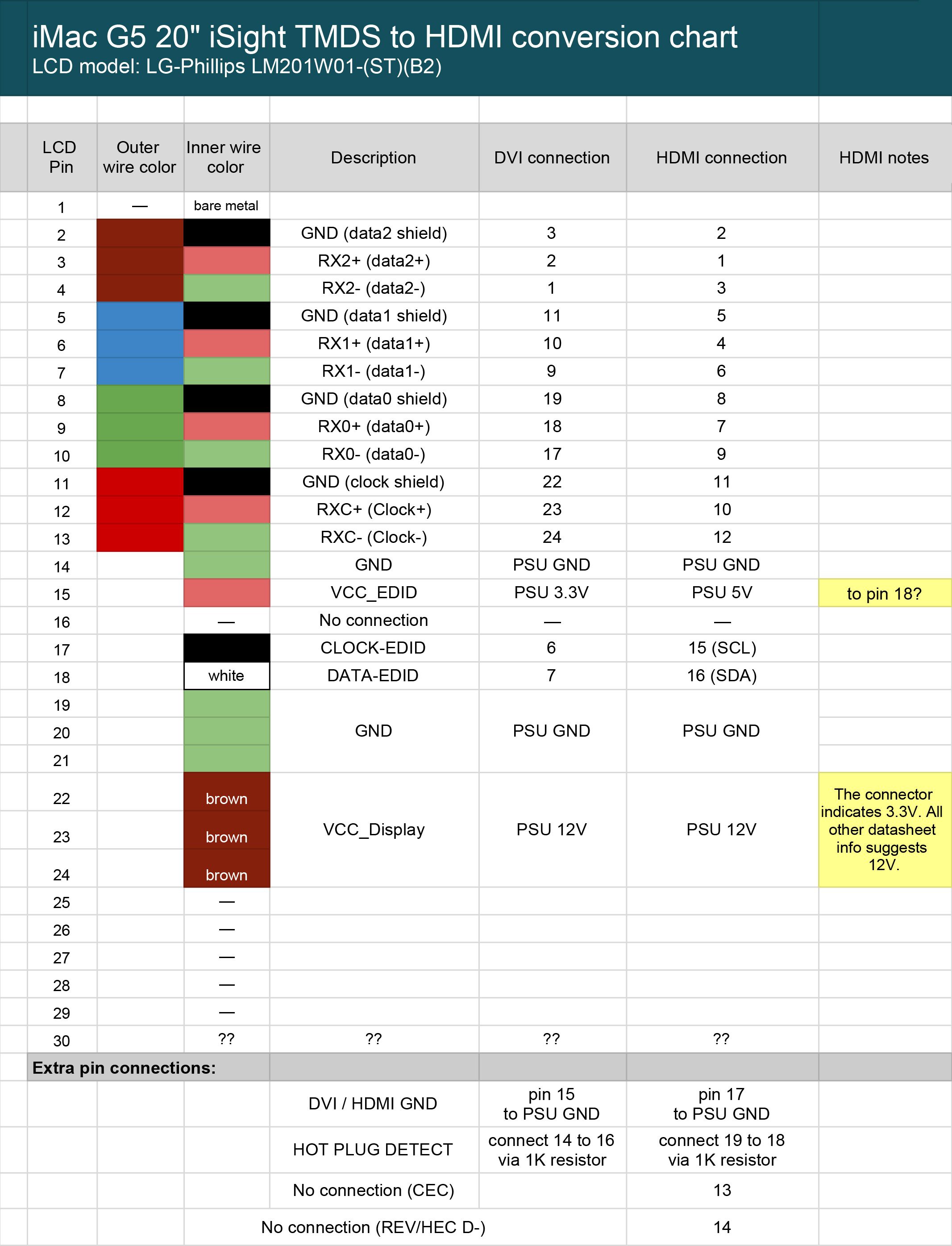
08/13/2020 at 15:37 • 0 commentsAfter several weeks of regular use, the monitor is still working fine with no known bugs. I realized in re-reading my logs that I never posted the final pinout chart for the monitor cable for connection to an HDMI connector (I've also included info for connecting it to DVI connector, for those who need that). This chart is the heart of the project and it took by far the most work to cobble together and test:
![]() For those of you who have made it this far in the project logs, and who are perhaps contemplating a similar hack on your own G5, please feel free to contact me with questions, either via direct message or in the comments below. Happy hacking!
For those of you who have made it this far in the project logs, and who are perhaps contemplating a similar hack on your own G5, please feel free to contact me with questions, either via direct message or in the comments below. Happy hacking! -
Success!
06/11/2020 at 15:40 • 0 commentsI'm pleased to report that the project is complete and the modification is working well. Here's a rundown on the final stages of the process:
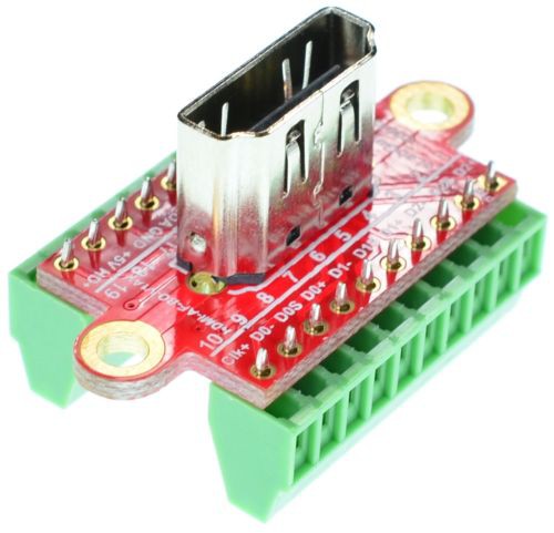
1) The female HDMI breakout I had originally ordered worked well for testing, but I soon learned that it was not easy to mount to the iMac case. So I ordered a different breakout from the same ebay guy (see the list of project components for a link), but this time I was smart enough to pay the extra $2 for him to solder the HDMI pins to the breakout board. This soldering requires a very fine soldering tip and strong magnification. The first time I tried this I used my daughter's microscope, but even that didn't keep me from somehow shorting two of the leads and ruining the adapter—so the $2 is worth it. The pins to the screw terminals are large enough that you can solder those yourself without too much difficulty.
![]()
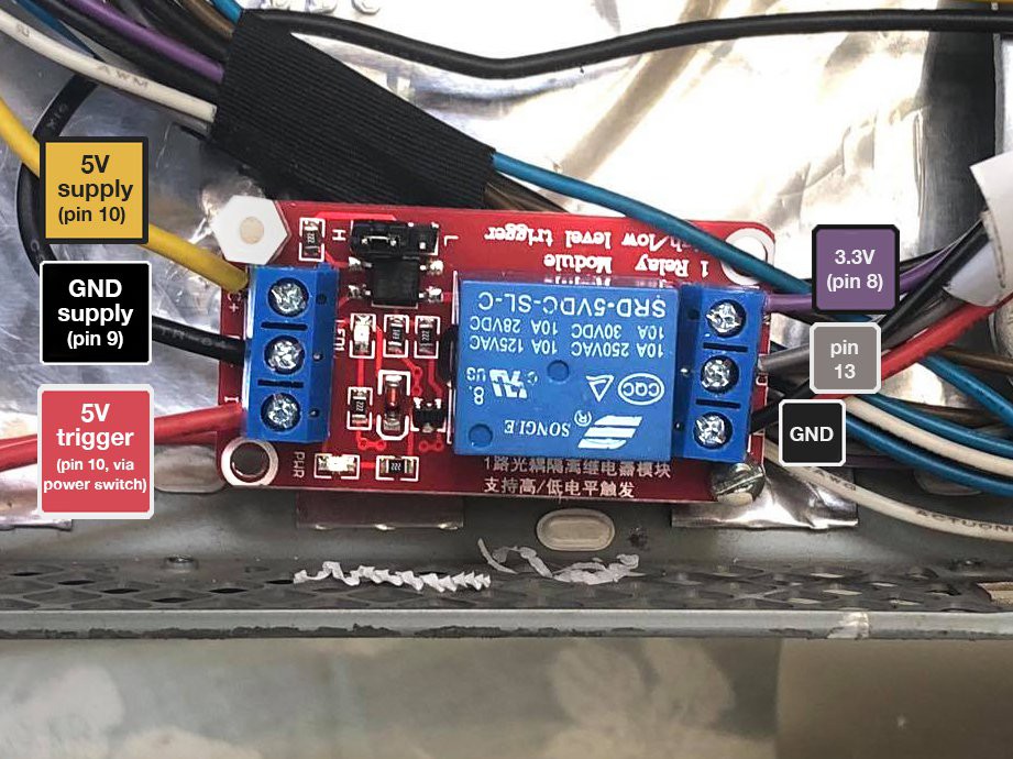
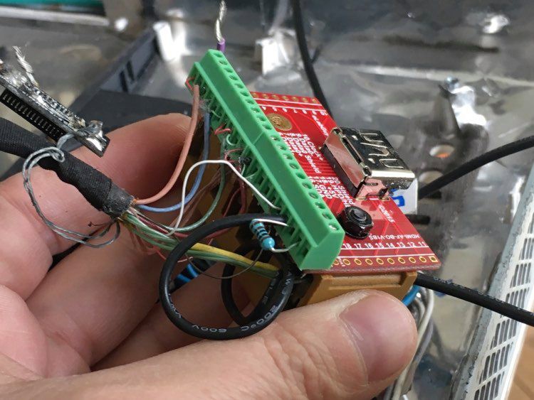
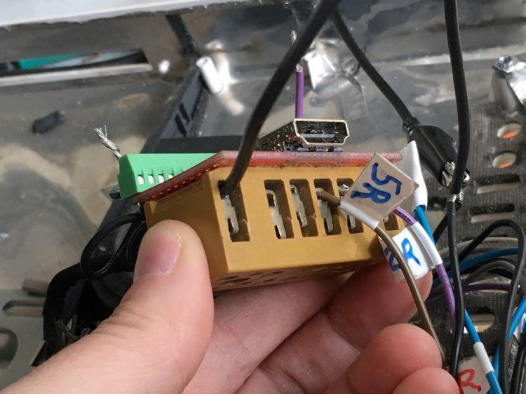
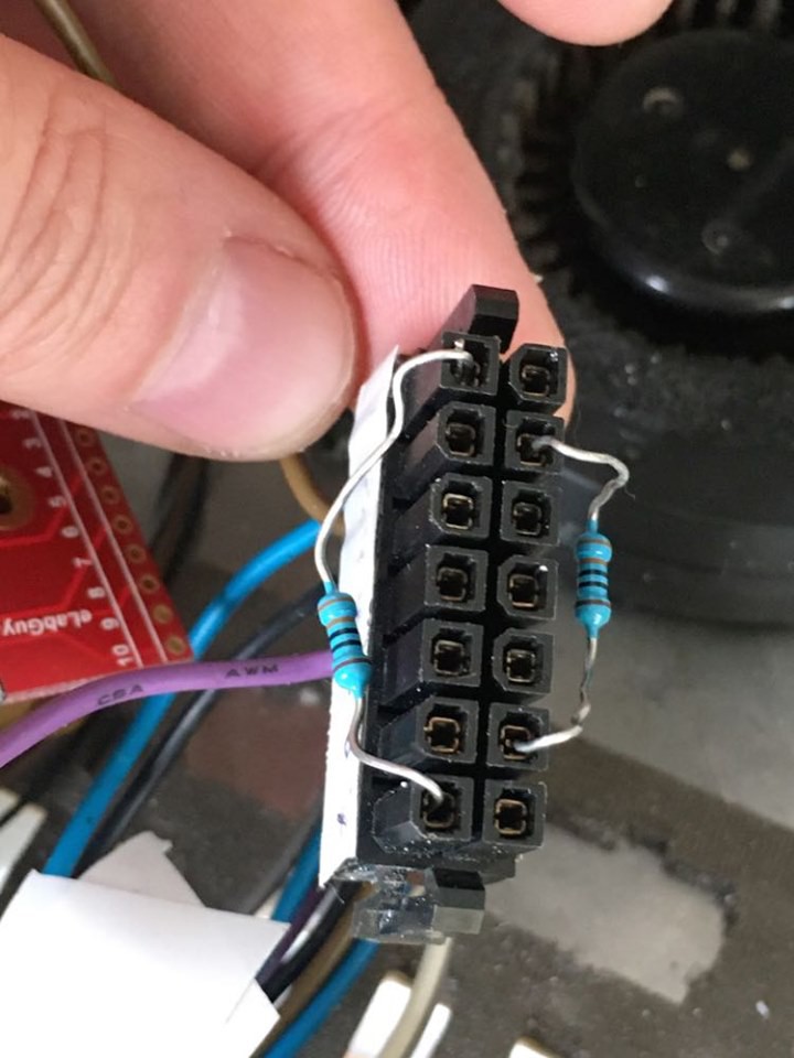
2) As mentioned in previous logs, power to the monitor is controlled by shorting two of the leads from the large female connector that normally plugs into the logic board. Shorting pin 13 to ground turns on the inverter, and shorting pin 13 to 3.3V turns off the inverter. This means that a standard on/off switch for power won't give us the control we need. So instead I used a 5V relay circuit, powering it with 5V from pin 10 and ground from pin 9, and routing a branch of that same 5V line through the user's main power switch to toggle the relay on/off. On the other side of the relay circuit there were also three wires: the common wire was pin 13, which the relay connected to either GND, or pin 3.3V (from pin 8). I used a relay where the trigger could be set either HIGH (in my case 5V) or LOW (ground)—either will work for this circuit. I mounted the relay to one of the plastic posts that was originally used to affix the logic board to the computer, and then used an M3 spacer to add support on the opposite corner.
![]()
![]()
![]()
3) Once you've wired the monitor cable into the female HDMI breakout, be sure to go through and make sure none of the data connections are shorted. All of the "shield" wires from the data lines are ultimately connected, so you should have continuity between HDMI pins 2, 5, 8, and 11. I somehow also had continuity between HDMI pins 10 and 11, where there should be no continuity. On very close inspection (using a high-powered magnifying glass) I saw that I had somehow nicked the insulation on the data line that went into pin 10. Because the shield lines are uninsulated, this caused a short. Difficult to diagnose, but easily fixed. I should also note that my research indicated that shortening any of the monitor cables could be problematic, as their resistances are carefully balanced to prevent distortions in the image. I don't know how much of this is relevant, but I tried to leave the cables intact and the resulting image is crystal clear.
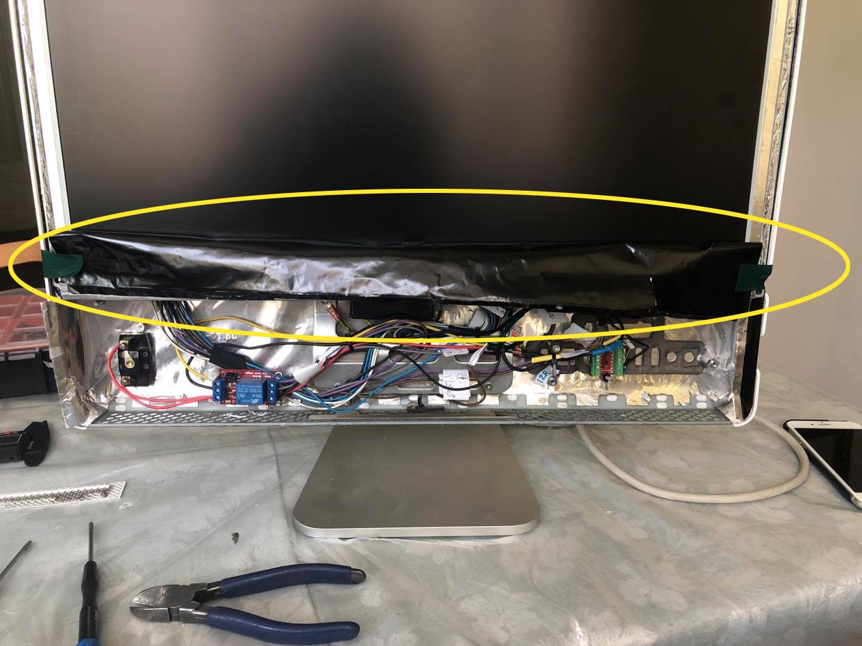
4) It is necessary to cut off and remove the thin plastic shroud that covers the area below the screen. It is metallic on the inside and if it comes into contact with live areas of your circuit could cause a short. This happened to me while demonstrating my work to my friend who commissioned the project, which was a bit embarrassing. So cut that thing off!
![]()
5) Pin 7 (LCD_PWM) and pin 1 (3.3V) should be soldered together and insulated with heat shrink tubing. I've read of others using a 1K resistor when shorting these pins, but I elected not to do that and haven't had any problems.
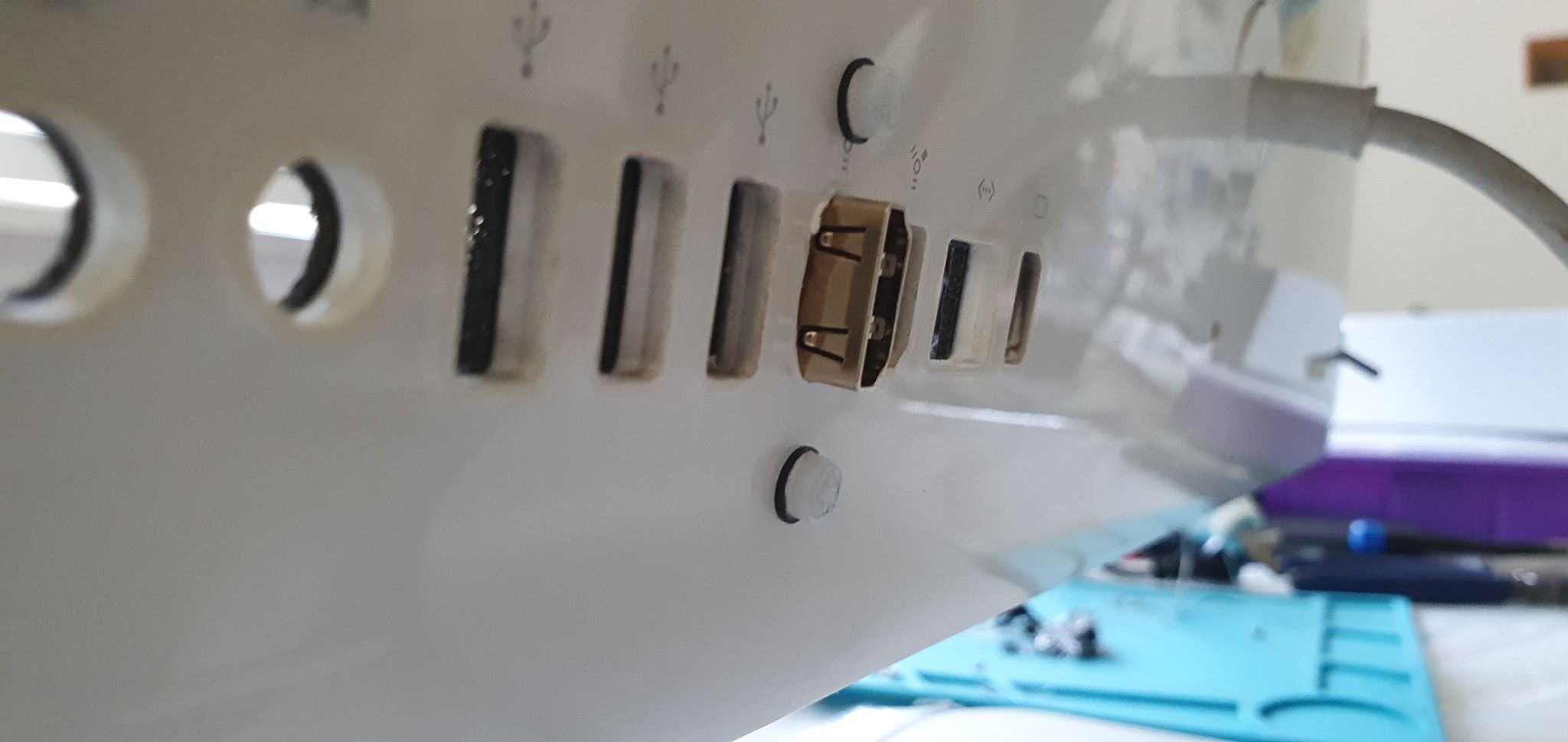
6) I mounted the female HDMI connector through one of the existing USB ports on the back of the iMac. Be sure you add some sort of insulating material over the pins on the connector's screw terminal block on the underside. If they managed to poke through the thin material apple has around the USB port they will come into contact with a metal layer, and this will cause a short.
![]()
![]()
7) I was initially a bit concerned about heat, so I thought I would reinstall one of the three fans that came in the unit. But these fans are not controlled by voltage alone, and without the logic board I couldn't figure out how to activate them. Once everything was up and running and I had reattached the iMac cover, I let the unit run for a few hours to test heat. The area near the inverter board was warm to the touch, which I think it normal, but it never got hot. The venting on the back of the iMac seems to be enough to keep things cool.
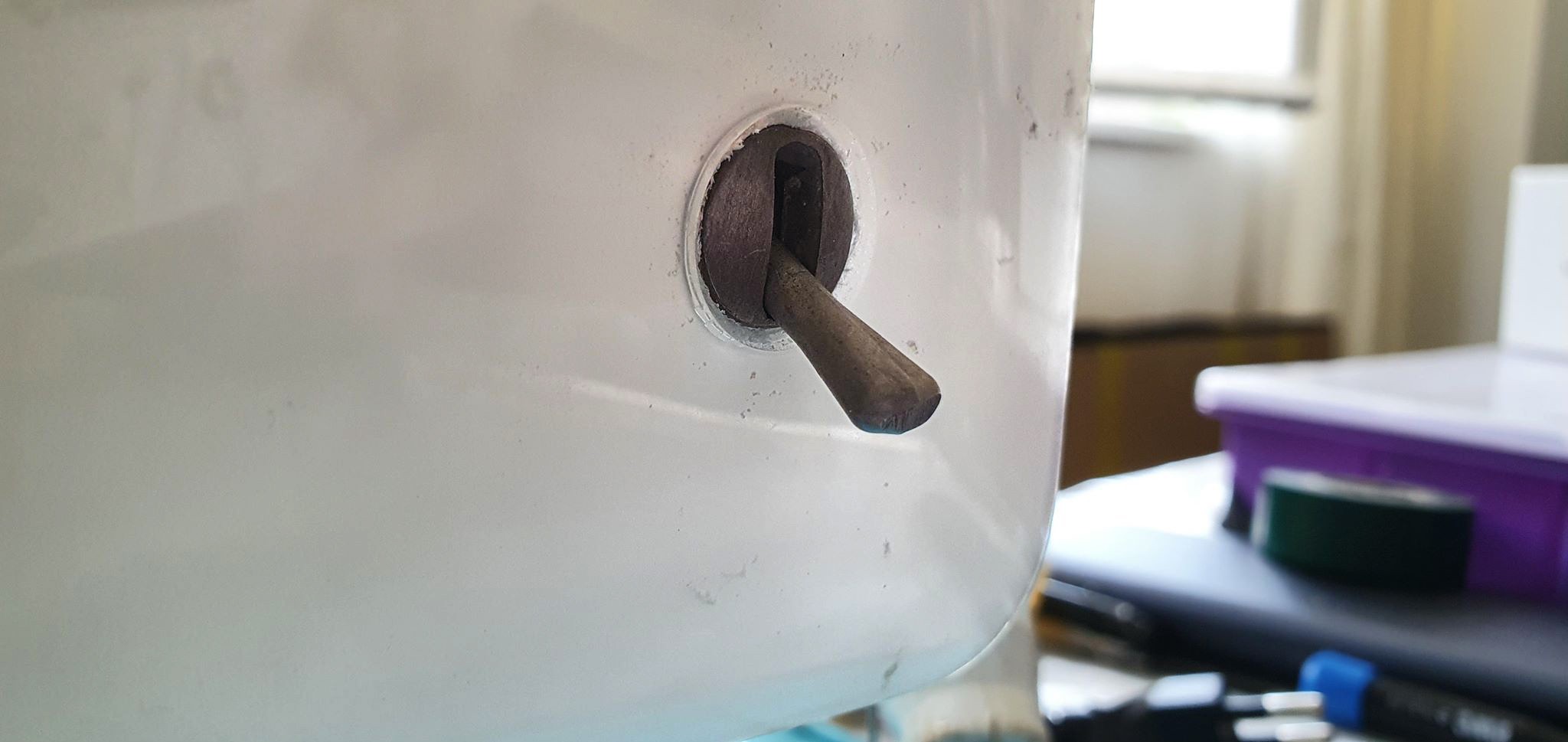
8) I had a few old vintage switches sitting around that were almost exactly the same size as the hole where the iMac power button is mounted. With some careful filing and some love from the glue gun, we have a main power switch with a solid, mechanical action that gives the project a bit of personality.
![]()
That's it! I'm happy to answer questions via DM if anyone is attempting this mod and needs clarification.
-
It's alive!
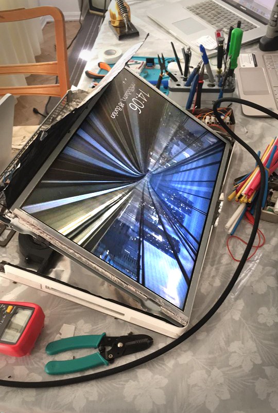
05/18/2020 at 11:49 • 0 commentsIf you've been following the past project log entries you'll know that I uncovered an inconsistency between how much voltage online sources say is needed to power the monitor (VCC 12V), and what the voltage that clearly labeled on one of the connectors (3.3V). I couldn't believe that Apple would make a mistake like this, so I hesitated to move ahead without some sort of confirmation (the service manual for this monitor is impossible to come by). I eventually lost patience and decided to throw caution to the wind and send 12V to the monitor to see what happened (sending 3.3V had zero result). After an afternoon of tinkering, including an hour of troubleshooting the strangest symptoms (I was misreading my multimeter—yes, it happens), I connected the monitor to my wife's laptop and this happened:
![]()
![]()
![]()
![]()
![]()
It's alive! There's still a lot to do, however, before wrapping this up:
- Replace female HDMI breakout board with a version where the connector extends further out from the unit. The breakout I have won't mount very well—it will need to extend beyond the board by 4-5 mm if I want to use one of the existing USB ports on the back of the machine. Otherwise I'll need to drill a completely new hole for the connector, and this will inevitably look like garbage.
- Add a 5V relay switch for the jumpered wires, to be activated by a manual switch mounted on the back of the machine. I'm considering a nice vintage switch with a solid mechanical action to give the project a bit of personality.
- Make sure there is no overheating happening. We are, after all, jumpering two wires in a way they aren't meant to be connected, so the possibility for unwanted heat or component failure—or even fire—is real. I'll also wire in one or both cooling fans and test.
- Consider adding a headphone jack and reinstall the speakers. Would need to test them first.
- Reassemble the machine.
I'm sure many makers can relate to that incredible feeling when you've been bogged down in a difficult project and suddenly it comes to life. It's really such an amazing moment!
-
Pinout for the 30-pin LCD connector
05/15/2020 at 06:39 • 0 commentsNot sure why, but tracking down a datasheet or service manual for the LG-Phillips LM201S01(ST)(B2) LCD monitor has been much more challenging than I would have thought (the datasheet appears to be available for download from this site, but there's a complex paywall that I lost patience with). After a week of searching, I pulled the following image off a Russian forum, and it claims to be the official pinout for the 30-pin monitor connector for our monitor:
This pinout matches most of the other data I have, except for one major inconsistency: this pinout indicates that VCC for the monitor is 12V power, while the labeling on the actual connector (the small connector opposite the 30-pin LCD connector) clearly says 3.3V.
So is VCC for the monitor 3.3V or 12V?
-
We are well begun
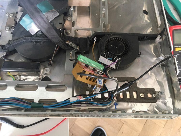
05/13/2020 at 20:44 • 0 commentsThis first project log entry comes after I've started the project, so I'll start by outlining where the project is at the moment and what the main challenges are. I've removed all the components from inside the computer except for the power supply, the inverter board, and the long snake of cables that connects the inverter board to the logic board. The fans, speakers, logic board, hard drive, and optical drive are all sitting in a pretty pile next to my workbench, likely destined for the e-waste bin (though I might reinstall a fan and the speakers if the project is successful).
![]()
The two main challenges for this project are 1) powering the monitor, and 2) retro-fitting the monitor cable to a female HDMI connector.
1) Powering the monitor
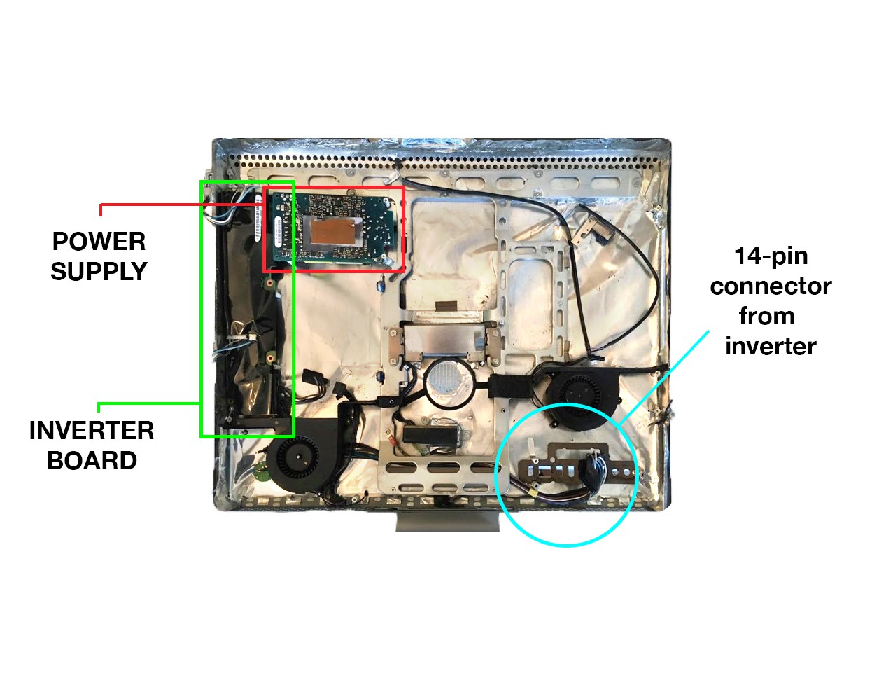
This process is not intuitive, and the only reason I know about it is from a few brave souls on the internet who have somehow figured out how to do this, most notably in this series of forum posts. On this model of iMac the power supply feeds into an inverter board, which in turn feeds the main logic board with a long snake of cables that terminate in a 14-pin connector. Power for the LCD backlight comes from four cable clusters coming off the inverter board which need to be somehow activated (more on this in a moment). The data for the LCD (and a bit of power) comes from the logic board. For this project we will continue using the inverter board to power the LCD backlight through some trickery that allows us to disregard the logic board entirely. If we look at the back side of the logic board (which we have removed and discarded) you can see some of the pinout information for the cables coming from the inverter. They are printed on the board opposite the female socket:![]()
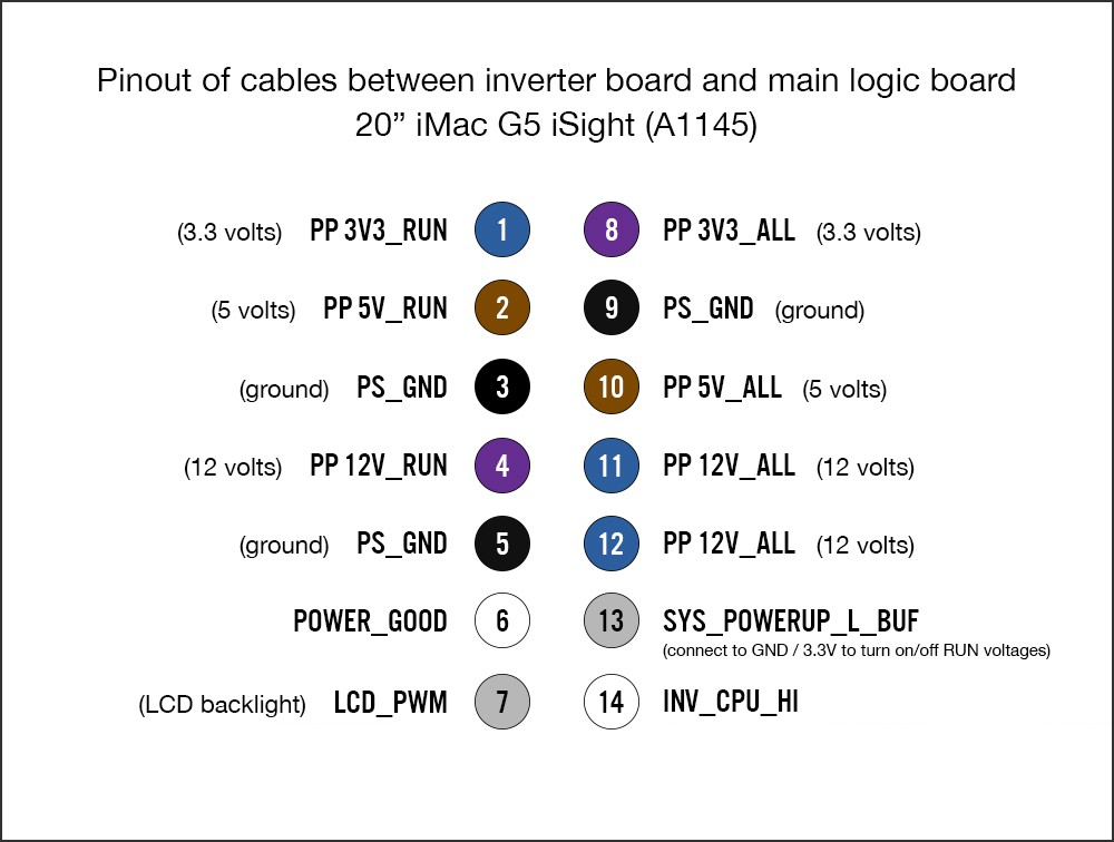
Working from that and other assorted sources floating around the internet, I've cobbled this pinout diagram:
![]()
These pin numbers are arbitrary (the connector isn't labelled, so I assigned my own numbers). All of the power pins marked "ALL" are hot whenever the computer is plugged into mains power. The RUN power pins are floating: they can be activated by tying Pin 13 low (to GND), and deactivated by tying pin 13 high (to 3V3_ALL). Tying LCD_PWM high (to 3.3V) activates the LCD backlight. I'm not yet sure what the function is for POWER_GOOD and INV_CPU_HI, or whether they are relevant to our specific mission. The YouTube user "3beltwesty" has a wonderful series of short videos demonstrating some of this.
I suspect that this process of activating and deactivating the RUN voltages is how the user will power the monitor on/off. I just need to figure out how to put in a switch in a way that is user friendly. I welcome any and all advice regarding this question.
2) Retrofitting the LCD cable for HDMI
This part of the project definitely feels like I'm out on the frontier, as I haven't been able to find nearly as much information as I would like about the LCD monitor cable pinout, and the information I do have is sometimes contradictory. In short, a cable from the logic board feeds the LCD via a 30-pin connector on the back of the monitor. The connector at the logic board end appears to be one of Apple's obscure proprietary connectors. Our objective is to hack the connector at the end of the cable (the opposite end from the 30-pin LCD connector) and affix a female HDMI connector in its place. We will then mount this female HDMI so that it protrudes through the back of the computer case for user access.I found a very helpful forum post with a chart of the pinout of the connector on the monitor and how it would convert to a DVI connector, but there are inconsistencies between that chart and the 30-pin connector on my machine (several of the wires are a different color, and somehow there is an extra wire coming from my connector that isn't accounted for in the chart). Here is a photo of the 30-pin connector that attaches to the LCD on my machine:
After peeling back some of the outer layers of the other connector (where the female HDMI hub will go), I was able to uncover a bit more information:
The labeling on this connector answers questions about some of the mystery wires, all of which are grouped together either as GND or 3.3V. But 3.3V seems strange, firstly because of the size of the monitor, and even more so because the chart I had found online lists these pins as 12V. So clearly there's some information I'm missing. I would welcome thoughts advice from anyone who has experience with this. Is VCC to the monitor really only 3.3V (as marked on the small connector)? Or is it 12V, as noted in several of the posts I've found online? This information is important to get right, as there is circuitry inside the monitor that could be damaged.
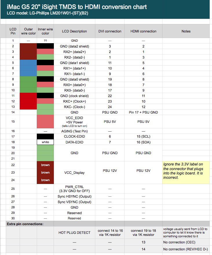
Borrowing from this beautiful LCD-to-DVI conversion chart I found online, I've plugged in my own values for what I *think* is a correct pinout for HDMI. I've marked the questionable information in yellow. Please bear in mind that this is untested:
UPDATED to include data from the following project log
![]()
I'm going to stop here for now. Hoping some of you can chime in regarding my questions in in the above HDMI pinout chart.
My hope is that even if this project fails, it will at least help a few people down the road who are attempting a similar mod.
Hacking a iMac G5 into an HDMI monitor
Resto-modding an old 20" iMac G5 iSight so the LCD can work as an external HDMI monitor for a laptop.
 For those of you who have made it this far in the project logs, and who are perhaps contemplating a similar hack on your own G5, please feel free to contact me with questions, either via direct message or in the comments below. Happy hacking!