VASILIS VORRIAS
-
M10CUBE looks like TOFU ?
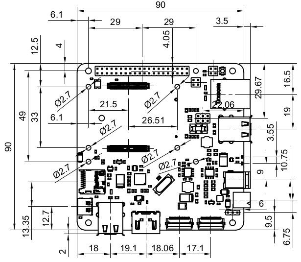
08/16/2021 at 11:51 • 0 commentsSome time ago tofu board came to market. https://tofu.oratek.com/#/
This is a carrier board for use with Raspberry Pi Compute Module 4.
As you can see there are a lot of similarities (concerning the dimensions 90X90mm)
Mounting holes are almost at same point as M10CUBE. Oratek made them at 4mm, 6.1 mm space from the PCB edge. I wander why did not make it 4mm, 4mm as M10CUBE.
Anyway the excellent TOFU board proved that 90x90mm PCB dimension is a golden rule on doing similar designs.
We are very proud to see that similarity in two different designs not knowing each other's work but having common sense and practical design ideas.
Having said that the tofu containers can be used as an inspiration and with a little modifications for M10CUBE
You can see the similarities on a M10CUBE prototype board and a tofu board
This is the TUFU module
![]()
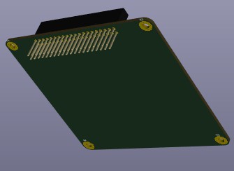
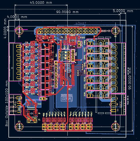
This is one of the M0CUBE I/O module (M10DX02-10) in KiCad
![]()
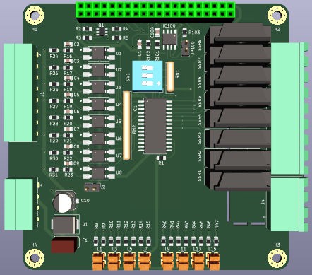
Same module in 3D
![]()
Soon will publish our new versions in CPU, PS and sensor boards -
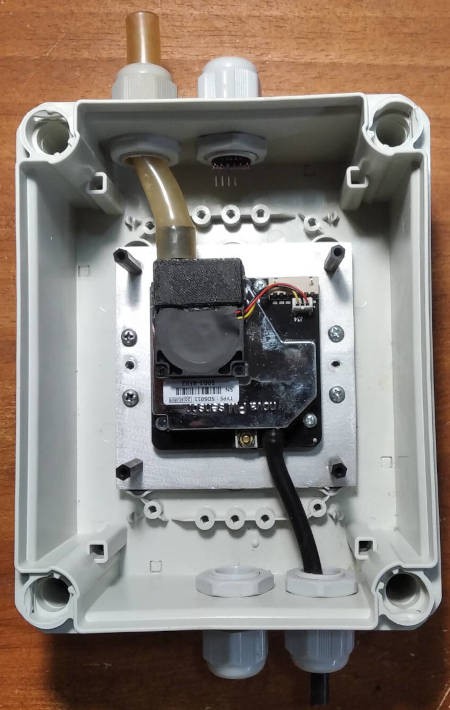
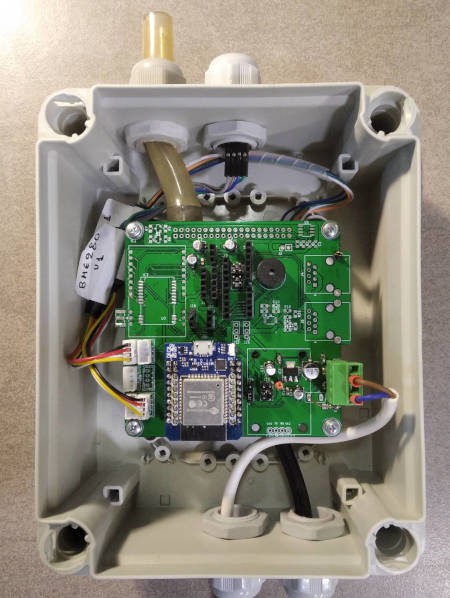
M10SENSOR CONSTRUCTION
05/09/2021 at 18:01 • 0 commentsOne photo a thousand words
![]()
![]()
Many extra features on the PCB are left unpopulated in favor of the upcoming revision
That will be the second generation of the PCB already on the drawing board -
SIX M10SENSORS SENDING DATA TO LUFTDATEN
05/09/2021 at 17:50 • 0 commentsHi everybody
Six sensors are sending data to https://sensor.community/en/ (aka Luftdaten) participating in a community sensor network in Volos, Greece.
you can access data to the following url
A/A NAME LATITUDE LONGITUDE PM2.5, PM10 TEMP, HUM, BAROM URL
1 SE0001 39.3606 22.9694 60264 60265 https://maps.sensor.community/#16/39.3606/22.9694
2 SE0002 39.3636 22.9498 61208 61209 https://maps.sensor.community/#16/39.3636/22.9498
3 SE0003 39.3708 22.9654 61284 61285 https://maps.sensor.community/#16/39.3708/22.9654
4 SE0004 39.3463 23.0015 61409 61410 https://maps.sensor.community/#16/39.3463/23.0015
5 SE0005 39.3694 22.9554 61566 61567 https://maps.sensor.community/#16/39.3694/22.9557
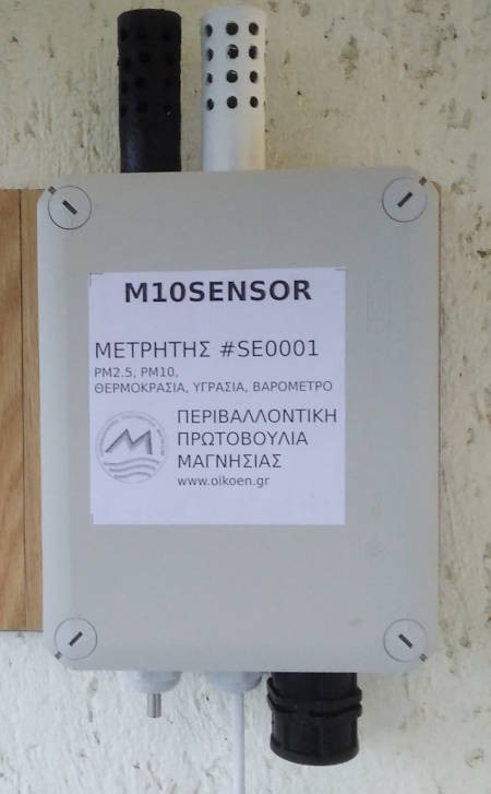
6 SE0006 39.3694 22.9554 61825 61826 https://maps.sensor.community/#16/39.3751/22.8845All six are contracted with same m10sensor hardware and this is SE0001
![]()
The only exception is SE0001 which has an extra DS18B20 temperature sensor for comparison reasons
-
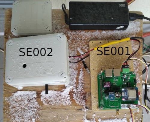
SNOW ON M10SENSORS
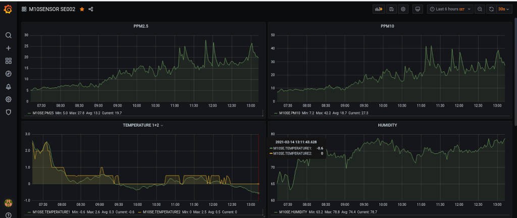
02/14/2021 at 13:25 • 0 commentsSnow came in my balcony without realizing it!. It came into my attention after watching the temperature data fro the two sensors (SE001 and SE002). I sow on Grafana that temperature1, humidity, barometric had no values (that is the MBE280 module) . When in balcony SE001 was covered with light snow. Still working but not the BM280 module...Get it out to repair the damage.
![]()
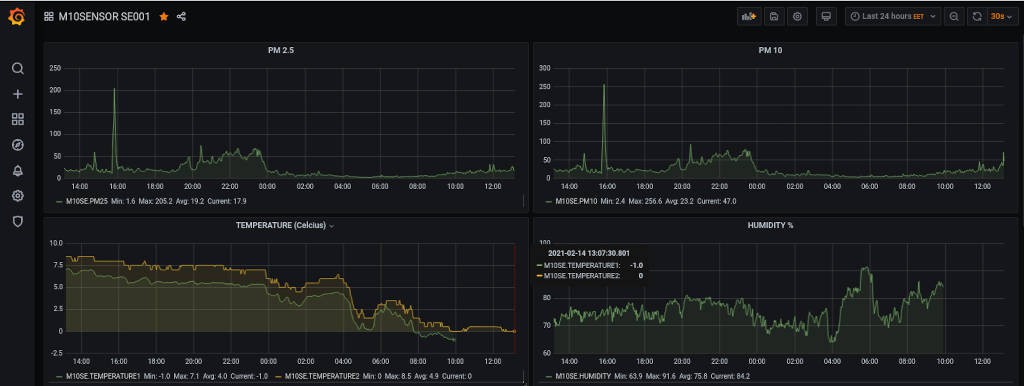
![]() SEE001 readings
SEE001 readings
temperature1, humidity (BME28 module) not working
temperature2 (DS18B20 external waterproof) working fine![]()
SEE002 readings
temperature1 (BME28 module) working fine
temperature2 (DS18B20 external waterproof) working fine -
M10CUBE PI PICO STARTED
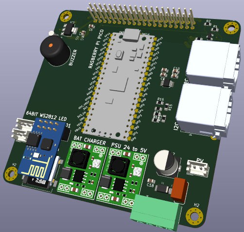
02/06/2021 at 18:45 • 0 commentsM10CP02-01 (CPU BOARD)
- Raspberry PI pin out with 40 pin connector as main interconnection between various M10CUBE modules
- Raspberry Pico module
- ESP01 For WiFi only
- I2C Extender
- SD card
- CON Li BAT with charger + booster to 5V
- CON PV for charging
- CON 64BIT WS2812 LED array. (can be used to display data or as emergency light)
- CON 5 - 24V input
- BUZZER
- ?![]()
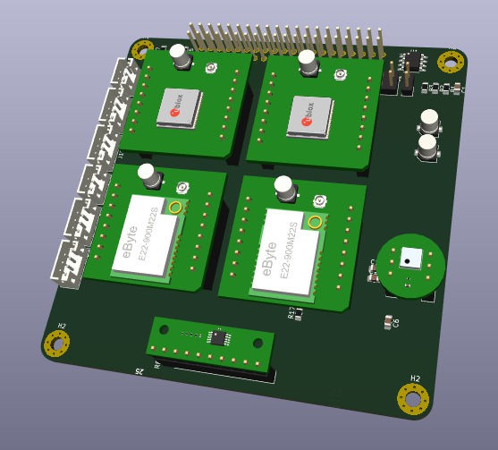
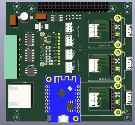
M10SE03-01 (SENSOR BOARD)
- Raspberry PI pin out with 40 pin connector as main interconnection between various M10CUBE modules
- Four mikrobus (https://www.mikroe.com/mikrobus) . We may extent it with 4 more pins. GPS, LoRa, Sensors will go on small breakout PCBs on mikrobus footprint so to use the many ready available mikrobus boards or to make your own, since mikrobus is open and free to use. Actually we are planning our own LoRa and GPS mikrobus boards to be available out of the box on the new design
- ASD1115 (4 channel I2C ADC)
- MEMS digital microphone
- GROVE connectors for I2C and Digital sensors
- More sensors on boardwith KICAD 6 (nightly build)
![]()
-
FIRST M10SENSOR FIRMWARE
01/25/2021 at 16:46 • 0 commentsThis is for developing and TESTING purposes for M10SENSOR board. Part of M10CUBE project.
Not for production ready. Modify it as you like. Use it as an inspiration as well.
It is only to show the concept to use many sub-modules on board.
It is our first attempt to make a test firmware for the many sub modules (Sensors, LoRa, GPS, etc) of m10sensor board.https://drive.google.com/file/d/14AIPzhoBPzz2Dnpc8aSQVgsGGyKpJLhR/view?usp=sharing
A word of notice:
we are on a redesign phase of the m10sensor board. Hardware may differ in the new board but the core of firmware done will remain the same. The way it is structured in separate header files will help everyone to delete and add any new hardware.
Enjoy it. -
THOUGHTS ON M10CUBE AFTER ONE YEAR
01/22/2021 at 19:35 • 0 commentsTHOUGHTS ON M10CUBE AFTER ONE YEAR
After about a year from introducing M10CUBE idea a lot have been happening.
First we have hands on first version of PCB for M10INPUT, M10OUTPUT, M10SENSOR, M10PROTOTYPE, M10PSU
Unfortunately because of the heavy work done on the M10SENSOR module, work on testing the other modules left behind.
Fortunately these months with testing left us experience for the overall design too. New hardware ideas found on the table as well.
So looking forward in overhauling the M10CUBE some things to consider are some thoughts.M10CUBE initial idea
The initial goal for M10CUBE idea with what is in mind after 1 year remains almost the same:To design development ecosystem, capable to accommodate known platforms like Arduino and Raspberry.
Not as separate products but as a unit and be able to interact each other. As far as we know there is no similar product in the market. M10CUBE must not only to able to be used as a testing, developing or production ready hardware but all its parts can be reusable for other projects (or come from other projects).M10CUBE can become for the microelectronics DIY community as the tool known as “swish army knife “
Not as good as it is each tool separately, but does the job. And does it well.
Many Hat or no Hat hardware exists to plug on the Raspberry Platform and many excellent ad-dons (shields or whatever word various Arduino incarnations use) exist for the Arduino Platform .
Many excellent PLC products exists for both Platforms. Many excellent company development hardware is out there. Without them new ideas will be impossible to implement.
Still it is almost impossible to get these boards and make a production system.
First of all because of the different PCB dimensions. That is natural.
Arduino’ s miracle made well known companies to embed Arduino UNO bus on their dev boards.That is very well done but now IOT explosion, the plethora of the proposed system and buses brought us in a situation without any standard on how all these devices to interconnect, easy and in an economical way.
Is it a standard like this exist and I am aware of it? May me.Not even the I2C bus has a standard pin out. Grove connector system is on the correct direction but it is not enough.
Some companies made attempts to fix the position of frequently used pins like SPI, I2C, UART but no one went beyond that to unite the two platforms in a full stack-able system so to be used from developing to production.Not to be misunderstood. There is no way to substitute a company's developing boards here.
Run your tests and experiment with these boards. Then design and build some PCBs with M10CUBE specs plug them together and voila!
The professional stack-able developing or production system is lying on your bench.
Make it a PLC , a Home Automation controller, an Environmental sensor or anything you like. Use the boards again and again in other projects.
The good thing is that you already know the enclosure dimensions and with a little copy paste your 3D printed enclosure is there! Share it with the community. That is a better idea on how all these can be connected together.We are not saying M10CUBE idea is best but we are trying to figure out how that can be done.
None seems to care . Maybe because that is impossible?All these excellent products (Arduino PLC and Raspberry PLC products, M5stack, the list is endless) have one thing in common. Their ego. Mostly the care about “themselves” and not what other companies doing. Not a bad thing because to build an excellent product you need to be specific in the design board. Then is the market. You design something to make money. That drives the hole Industry. And that is a good thing. But not always good for the end user.
The money lost the last 40 years because the companies fighting to push their own standards to consumer products. Money out of our pockets . Lost for ever.
Just to remind the mobile charger connector. So many incarnations until everybody confirmed on usb. So bad for our pockets and most for the environment. How difficult was that?M10CUBE tries to overcome that attempting to make a concept, a platform, a "glue", a development platform, a production ready hardware or all the above. M10CUBE is a dream to help the community to use ARDUINO and RASPBERRY platforms like a LOGO.
The power of M10CUBE is not the individual PCBs but the modularity offered by the concept.We continue to say M10CUBE is kind of “hardware agnostic” means that new hardware ideas can lay on it as long as M10CUBE is solid. That is the electric and mechanical specifications are well designed and accepted.
In a sense M10CUBE is not magic at all. It is common sense. Proposes a well designed environment to embrace all problems arisen from a world totally without any standards on that field. Not an easy thing or if I may say, very very hard to achieve.
That is why needs M10CUBE needs a lot of inspiration a lot of discussion, a lot of courage and a little bit of luck.
But there is hope.
M10CUBE hardware specs are still for discussion before we are going back to drowning board.
1 - A hardware platform that will accommodate The Raspberry PI 4.
Plans for future. Compute module or other modules is easy to design.2 - A 40 long pin connector for interconnecting the various stacked PCBs. The connector has the same footprint as the Raspberry Pi.
Plans for future. A high speed duplex differential bus can be used instead. Same idea used in modern PLCs today. All other hardware on board can remain the same. That is easy for PCB designers to make something completely different as the inter-board communication as concern.
3 - A proposition for PCB dimensions 90x90mm
- A proposition for outer dimensions of the box 100x100mm. A possible construction of 100x100x100 mm cube can be constructed accommodating various modules.
4 - Directions and template hardware will help others to design various boards using STM32, Analog, CAN BUS, Encoders etc. Only imagination stops someone to design something useful and benefit from others work on M10CUBE.
5 - Project always will be OSHW certified. So you can copy and make money if you like. In fact we like to see you doing it.
6 – The need for a plug-in system for the various hardware used on board.
That was done in an idea last year but it is abandoned. We may today find a better solution.
See on photo last year's abandoned idea![]()
So many years in industry one thing we learn for sure. The only way for a product to be a success story (and probably designers make money) must be open source and best to be OSHW certified.
One thing we learn from our testing on m10sensor was, that plug in modules saved our time . So on redesigning we will consider all components to have a snap in capability.For instance when testing m10sensor boards with LoRa subsystem lot of m10sensor PCBs destroyed (soldering and unsoldering the modules) . The same for GPS.
So there is an urgent need for all subsystems to be plug in and play. A small breakout PCB is needed. That is to be able not only to remove the broken sub-module, but also to unplug it and reuse it in another project. That must be applied for all sensors used, LoRa and GPS subsystem.
Which bring us to one million dollar question. What is the correct footprint (pin-out) for the breakout PCB that will accommodate all the above?
OK still looking. We are sure we will find it.
Why? Because it is common scene to exist and then we will find it.Is M10CUBE for dreamers? Yes it is. M10CUBE as we dream it is not static but dynamic. Nobody knows how it can be in an other incarnation after some years.
Do not forget Apple, Arduino, Raspberry came to light because dreamers are real. Well better to say visioneers.
In the end only dreamers will drive us to Mars
So we are keep dreaming and keep working hard to find solutions that will make M10CUBE a product useful to the community.
Only imagination will stop someone to design useful things on the M10CUBE ecosystem and others to benefit from his work.
-
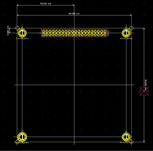
90X90mm PCB
01/21/2021 at 12:37 • 1 commentIt looks that 91X91 PCB dimension is a bit strange. 90X90 seems more appropriate and does not reduce really the real estate of the board. PCB Calculations are easier that way.
A small reposition on the 40 pin Raspberry connector made so the center of the connector to be aligned with the center of the mounting holes. The same way things done on the Raspberry Pi .
It is very crucial on this redesign to fix PCB outlet, mounting holes and Raspberry PI 40 long pin connector that connects various boards together.
PCB is still open for suggestions.
We are talking now with a very old and established company in electronic design.
Hopping that discussion will produce an even better M10CUBE design for the community.
A PDF and a step file will help you to see the actual proposition
We are open to discussions and criticism.
![]()
![]()
1 - STEP file
2 - PDF filehttps://drive.google.com/file/d/1yRPqU383x6fnzrjMYXi4AUmQ6xDtixmj/view?usp=sharing
https://drive.google.com/file/d/1-Jwz05DQahxnaDgEAwje6dV2fpPQ8MXz/view?usp=sharing
-
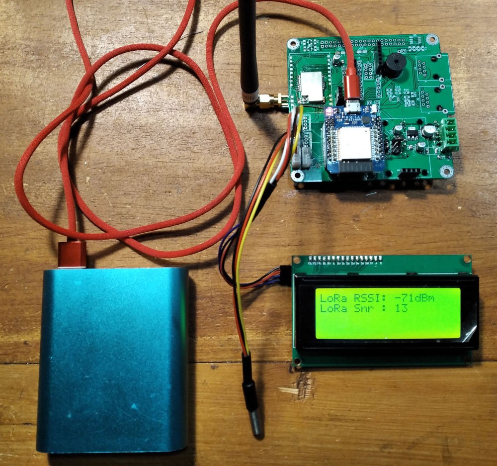
LoRa ping pong with buzzer sound
01/14/2021 at 13:05 • 0 commentsLoRa ping pong test using the on board buzzer for ping pong notification. Modified for m10sensor
![]()
-
LoRa
01/11/2021 at 10:47 • 0 commentsm10sensor is undergoing LoRa first tests. A problem fount on some tracks connecting NSS and SCK pins from E22-900M22S LoRa chip to SS_LORA and SCK_ESP pins of ESP32.
So that you see is the result of the test. The brilliant library used is made by the excellent engineer Stuart Robinson.
https://stuartsprojects.github.io/
https://github.com/StuartsProjects/SX126X
As soon tests completed and all subsystems go I will publish the total firmware.
![]()
M10CUBE
M10CUBE (M10 in short) is a modular controller box with cube dimensions 10x10x10cm. Raspberry bus will be used for the first incarnation.
 SEE001 readings