VASILIS VORRIAS
-
M10SENSOR BUILD AND WORKING
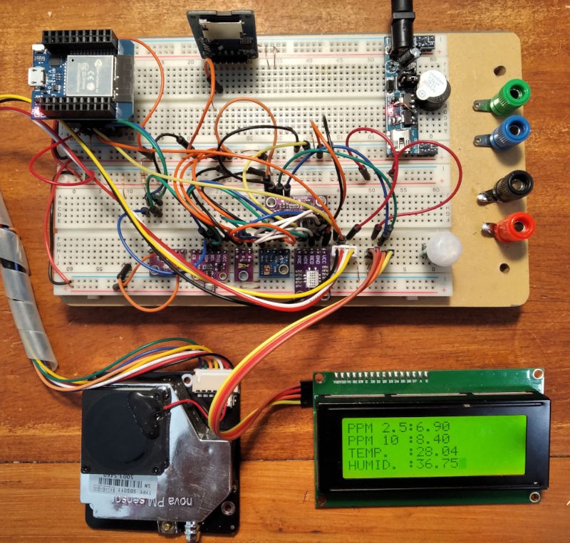
11/09/2020 at 20:53 • 0 commentsToday 09/11/20 the "real" m10sensor is build and working perfect.
m10sensor was build and thankfully no major problems on the PCB. Minor things that can be correcter to a next version.
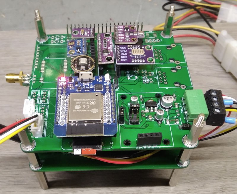
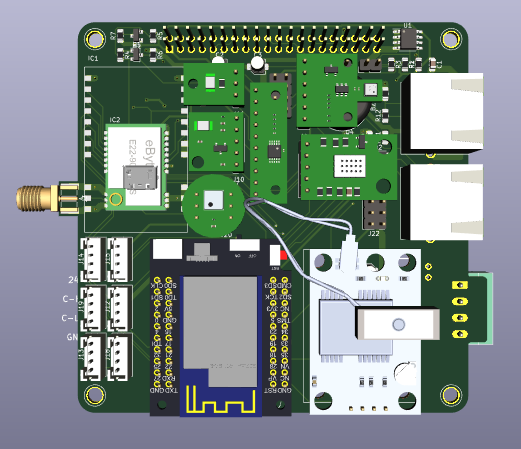
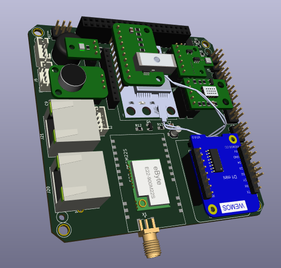
So far we build the stand alone sensor (no need for the Raspberry to be on the field but still you can plug it in).
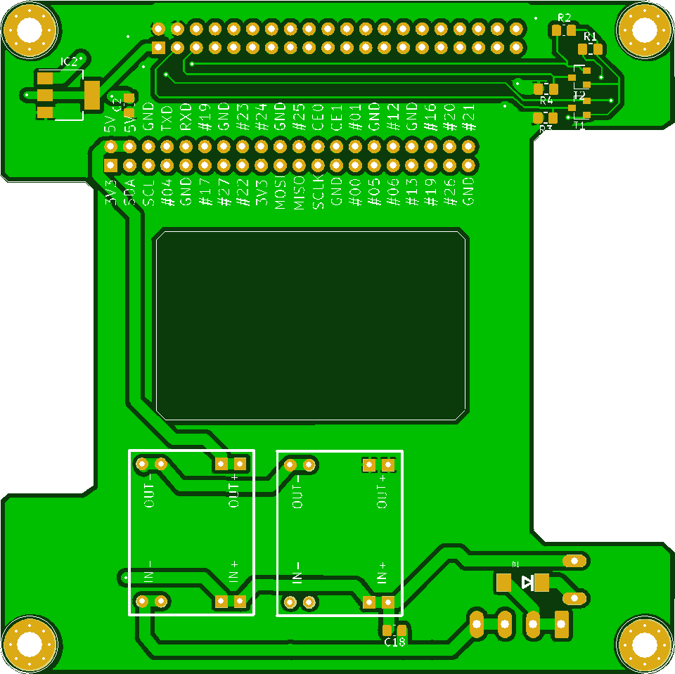
Underneath is the PCB hosting the SDS011 dust sensor. Raspberry module goes on top of that (next image)
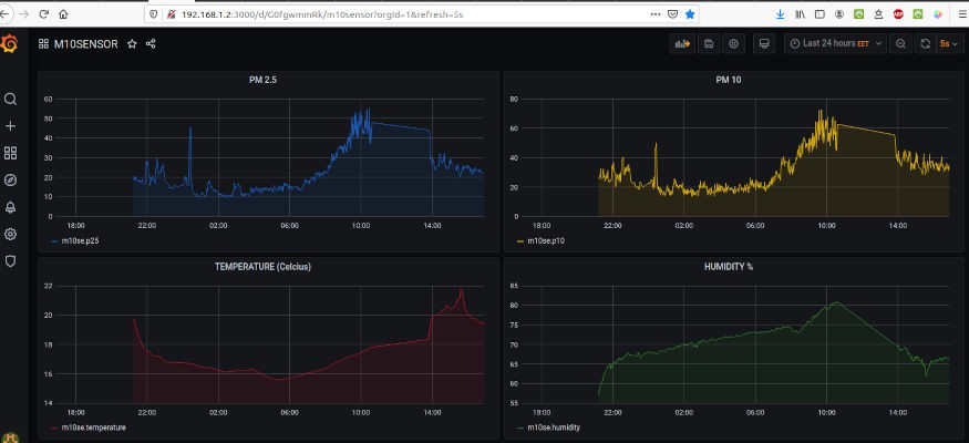
While waiting to receive Lo-Ra module, GPS, and the I2C extension components (the unpopulated space on m10sensor PCB) enjoy in the image of the m10sensor collecting real time environmental data and sending them in influx database and grafana running on Raspberry Pi 4. All sensors are working perfect.
We are also preparing a platform (in WordPress) for searching the sensors on a map and view real time data in grafana.
OTA is working as well so I do not have to go to the balcony every time m10sensor needs (that is very often indeed ) improved firmware.
![]()
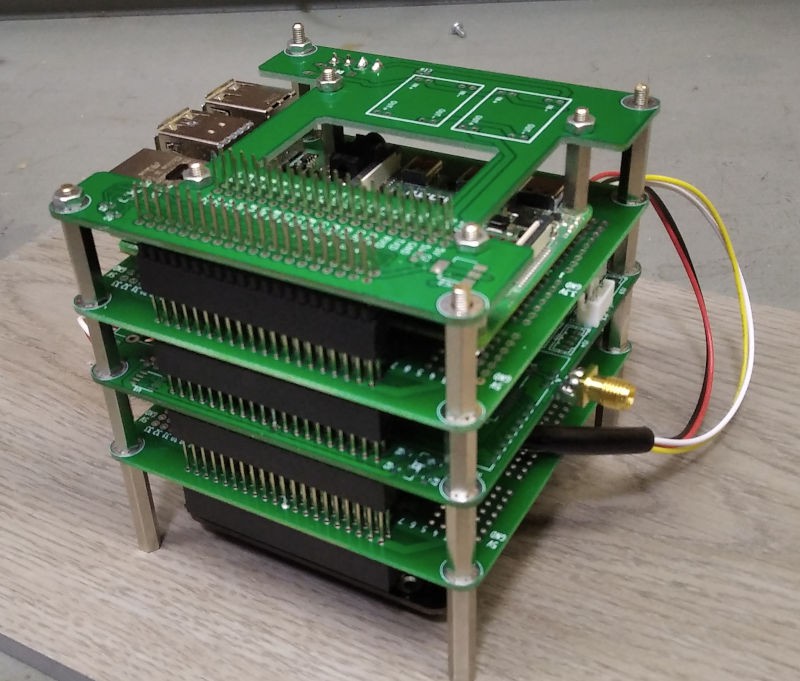
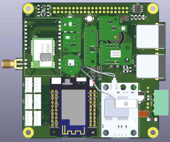
Below is how the M10CUBE looks like with Raspberry modules attached.
At the moment only spacers keep boards together since the boxes are in development.
![]()
-
ARRIVIAL OF PCBs
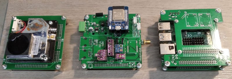
11/07/2020 at 17:54 • 0 commentsAll five PCB types arrived some days ago. I Started building the M10CUBE system and checking for errors.
Then trying to fix the fitting inside frames.
From first impressions only minor problems. Will be fixed on the next version.Soon test results will be published.
First version of the sensor board firmware is written and sends data to the influx and grafana running on the Raspberry .
I will publish the firmware as soon as testing is OK.
![]()
![]()
![]()
If you need any info please ask. I will be happy to provide.
-
PRODUCTION APPROVED
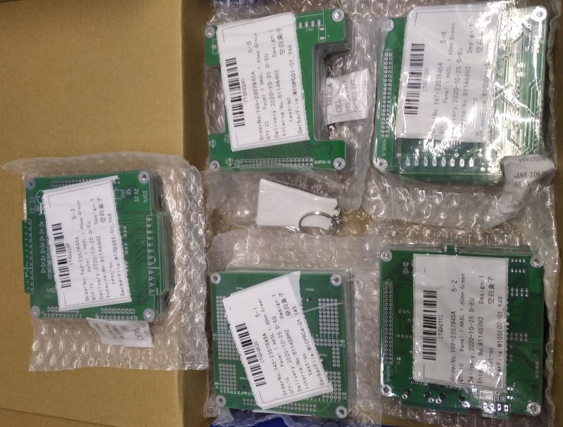
10/23/2020 at 10:33 • 0 commentsToday after many delays due to problems on the boards, production approved by jlcpcb.com for all 5 types of M10CUBE PCBs designed so far.
While waiting for delivery of the PCBs we are developing a first version of the firmware to support all boards.![]()
![]()
![]()
![]()
![]()
-
PROTOTYPE BOARD
10/19/2020 at 17:21 • 0 comments![]()
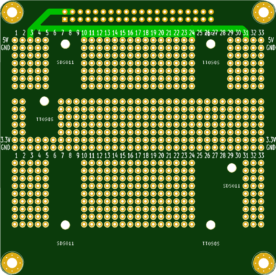
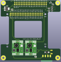
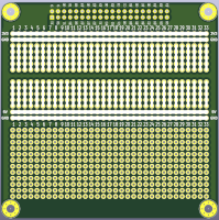
Prototype board, plus Breadboard area, plus holes to mount the FINE DUST. PM 2.5 & PM 10
MODULE SDS011This board (without the SDS011) will be used as the bottom board in the RASPBERRY frame.
-
SENSOR REDISIGNED
10/19/2020 at 17:13 • 0 comments![]()
Development and fabrication of M10SE01-01 stopped in favor of M10SE02-01 Some serious issues discovered during building in Breadboard an experimental version of M10SE01-01 circuit and that was:
UART0:RXD and UART0:TXD pins can not be used and better remain only for programming the ESP32 MINIKIT. Having one UART less we decided to remove RS485 communication.
The RS485 idea was to connect other M10SE01 modules distant apart for sensing the near by environment. Since that is not possible any more an I2C solution was adapted using the ideas taken from a Sparkfun design.
The 2 RJ45 connectors remaining in hope to daisy chain from one board to the other the 2 differential I2C signals. Board sent for fabrication
SPECS:
Ambient Light, UV Light, VOC, Digital Sound (MEMS)
Temperature, Humidity, Barometric
ESP32 minikit, GPS, LoRa, I2C EXTENDER (2XRJ45 FOR DAISY CHAIN)
-
DESIGN PROBLEM IN M10SE01-01
10/08/2020 at 10:50 • 0 commentsDevelopment and fabrication of M10SE01-01 stopped in favor of M10SE02-01
Some serious issues discovered during building in Breadboard an experimental version of M10SE01-01 circuit and that was:
1- UART0:RXD and UART0:TXD pins can not be used and better remain only for programming the ESP32 MINIKIT.
Having one UART less we decided to remove RS485 communication. The RS485 idea was to connect other M10SE01 modules distant apart for sensing the near by environment. Since that is not possible any more an I2C solution was adapted using the ideas taken from a Sparkfun design. The 2 RJ45 connectors remaining in hope to daisy chain from one board to the other the 2 differential I2C signals.
Design and testing among others in progress before sending board for fabricationDigital MEMS microphone for sound level metering
GPS
LoRA
![]()
-
FINAL PCBs
10/02/2020 at 10:35 • 0 comments3/09/2020
At last after many days of redesigning and trimming ready to send for PCB fabrication (hoping everything is correct.) a complete set of M10CUBE modules.
New naming convention is introduced
M10PR01-01 (Prototype board and can be used as the bottom PCB on CPU frame)
M10PS01-01 (PSU module)
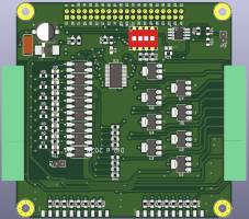
M10DX01-01 (8xDigital Inputs + 8xDigital Transistor Outputs)
M10DO01-01 (8xRelais Outputs 16A)
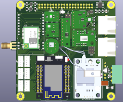
M10SE01-01 (Sensor board + ESP32 + RS485, +LoRa + GPS)![]()
![]()
![]()
![]()
![]()
All design files can be found on GitLAB
-
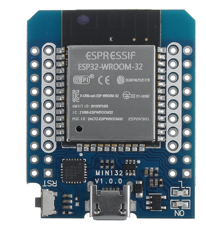
ESP32 MINI KIT
09/19/2020 at 10:18 • 0 comments19/10/2020
Wemos mini D1 (run out of pins) changed in favor of ESP32 MINI KIT. More power and more pins. That m10-sensor version fulfills all my expectations for this modular board to be part of a big sensor network we are building in Volos Greece and can fulfill the German Luftdaten Air monitoring network . Well to be honest we wanted to go one step beyond. Not exactly sure if we succeed, but we are trying hard hoping this work to be inspiration for others since it is modular and contains the 40 pin Raspberry connector. That is can be used as Raspberry HAT and use the power of the Raspberry for more compute work (SQL server, LORA-WAN gateway e.t.c). Ready to send for PCB fabrication.
Contains:
1 - TEMT6000 sensor (AMBIENT LIGHT)
2 - ADC ADS11153 - CJMCU-680 or BME280 sensor (TEMPERATURE, HUMIDITY, BAROMETRIC).
4 - GPS (RS232 module)5- CYML-8511 sensor (UV LIGHT)
6 - VOC (Volatile Organic Compound) CJMCU-4541 sensor.
CARBON MONOXIDE CO , ITROGEN DIOXIDE NO2 , THANOL C2H5OH
HYDROGEN H2, AMMONIA NH3, METHANE CH47 - Digital Sound Level
INMP441 MEMS MICROPHONE8 - RS485
9 - LoRa (E22-900M30S or E22-900M22S)
PLUS
- ESP32 Mini kit
- SD card
- One 4pin JST 2mm Connector for SDS011 (Fine Dust PM 2.5 and PM 10 sensor)
- One 4pin JST 2mm connector for experiment (only +3V3 and GND connected)
- Two 4pin JST 2mm Connectos for digital IN/OUT (can be used as for DS18B20 sensors) - Two 4pin JST 2mm connectors for any Grove I2C Sensors
- Optional switching PSU module 24V - 5V (m10-sensor can be used as autonomus)
- Optional 24V connector (same as other M10CUBE modules)
- Optional 3V3 PS (If more power 3V3 from needed than ESP32 module can provide)![]()
-
M10-SENSOR
08/05/2020 at 06:11 • 0 comments05/08/2020
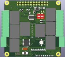
More on m10-sensor PCB. That is almost the final population concerning m10-sensor. The jumpers on the right change the functionality of the board. Many boards can be connected via external cable with RS485, by modifying the jumpers, board can be used for various sensors. That is because Wemos D1 mini has not enough pins. Circuity is done. Routing is not.
![]()
Planning the same board but with Wemos D1 ESP32 version. That is pin compatible with Wemos D1 mini ESP8266 (white coloured pins on ESP32 image)but have more pins (and power). That way the space occupied by the jumpers is not needed so can be freed to accommodate the bigger Wemos D1 mini ESP32 (6 Euros!).
![]()
-
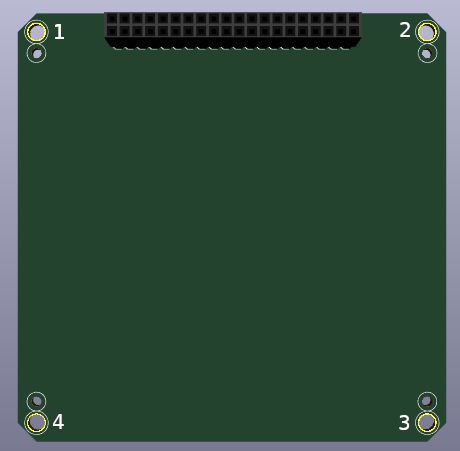
M10-PCB-TEMPLATE
07/18/2020 at 13:11 • 0 comments18/07/2020
This latest version of m10-template includes a modification to corners. The larger space that exists between PCB and the frame leaves room to pass up to 5X 1mm wires for inter M10CUBE connection like carrying high speed LVDS RS485 connection between I/O modules and CPU, or getting PSU values to other PCB for monitoring. In general all 4 corners can accommodate extra wiring for passing through to other PCBs in the M10CUBE space for signals that not met by the 40 pin RASPI connector. Since has no cost It will be an option for someone to use.
Big holes 1,2,3,4 are 3.3 mm in diameter. That is for the pass through 3mm threaded rod to mechanical stabilize the frames.
small holes are for mounting the PCB on the framePCB dimension remains the same 91X91 mm
![]()
M10CUBE
M10CUBE (M10 in short) is a modular controller box with cube dimensions 10x10x10cm. Raspberry bus will be used for the first incarnation.