-
1Remove the fuser and insert 2.7K thermistor
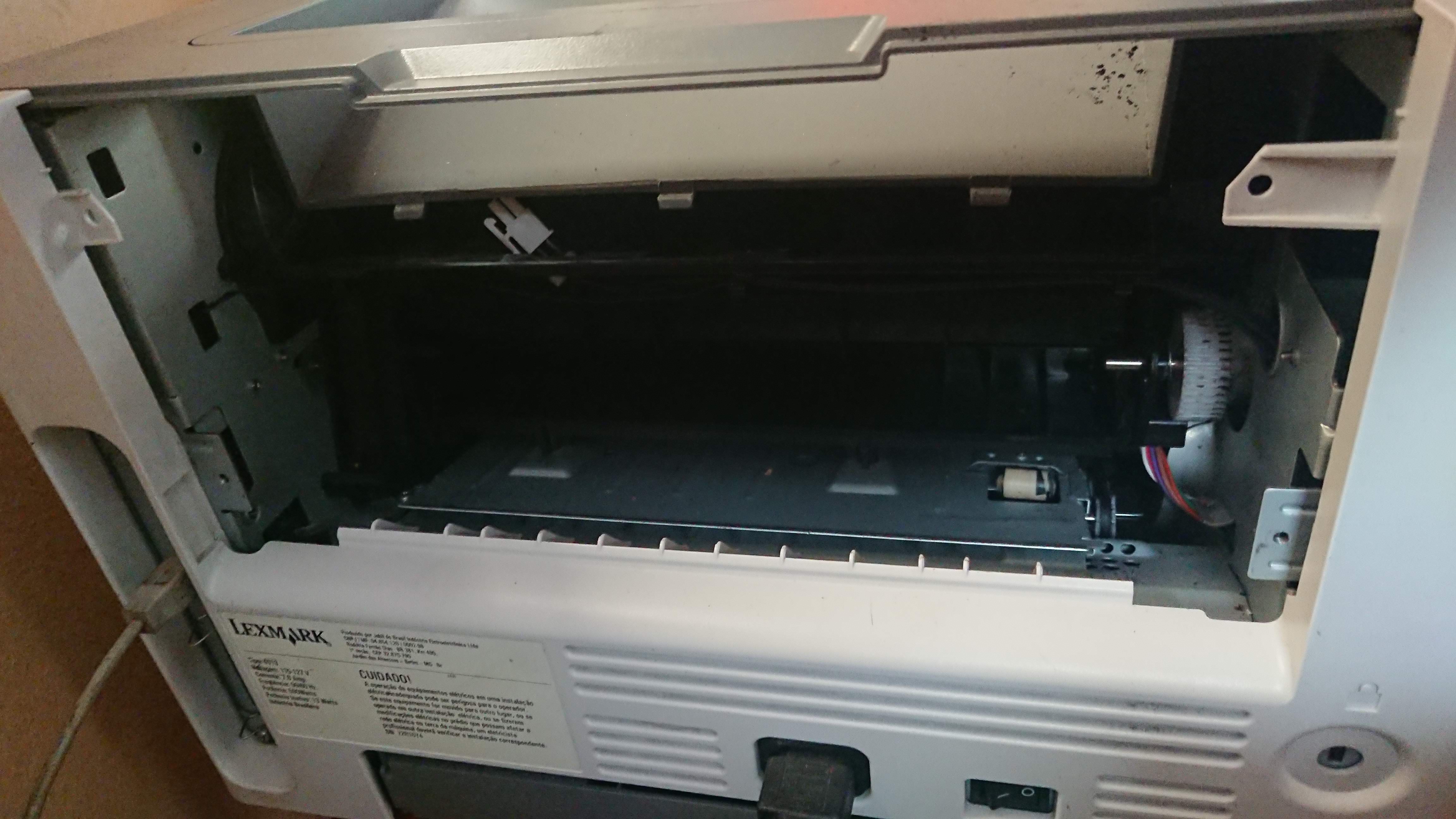
The first step is to remove the printer fuser. Refer to the service manual in the attached files, it explains everything clearly.
You may also remove the curly thing in the back that redirects paper. Save the paper exit sensor for later.
![]()
Once the fuser's been removed, cut the thermistor cable and solder a 2.7K resistor in its place.
-
2Cut the paper platform and insert new rollers
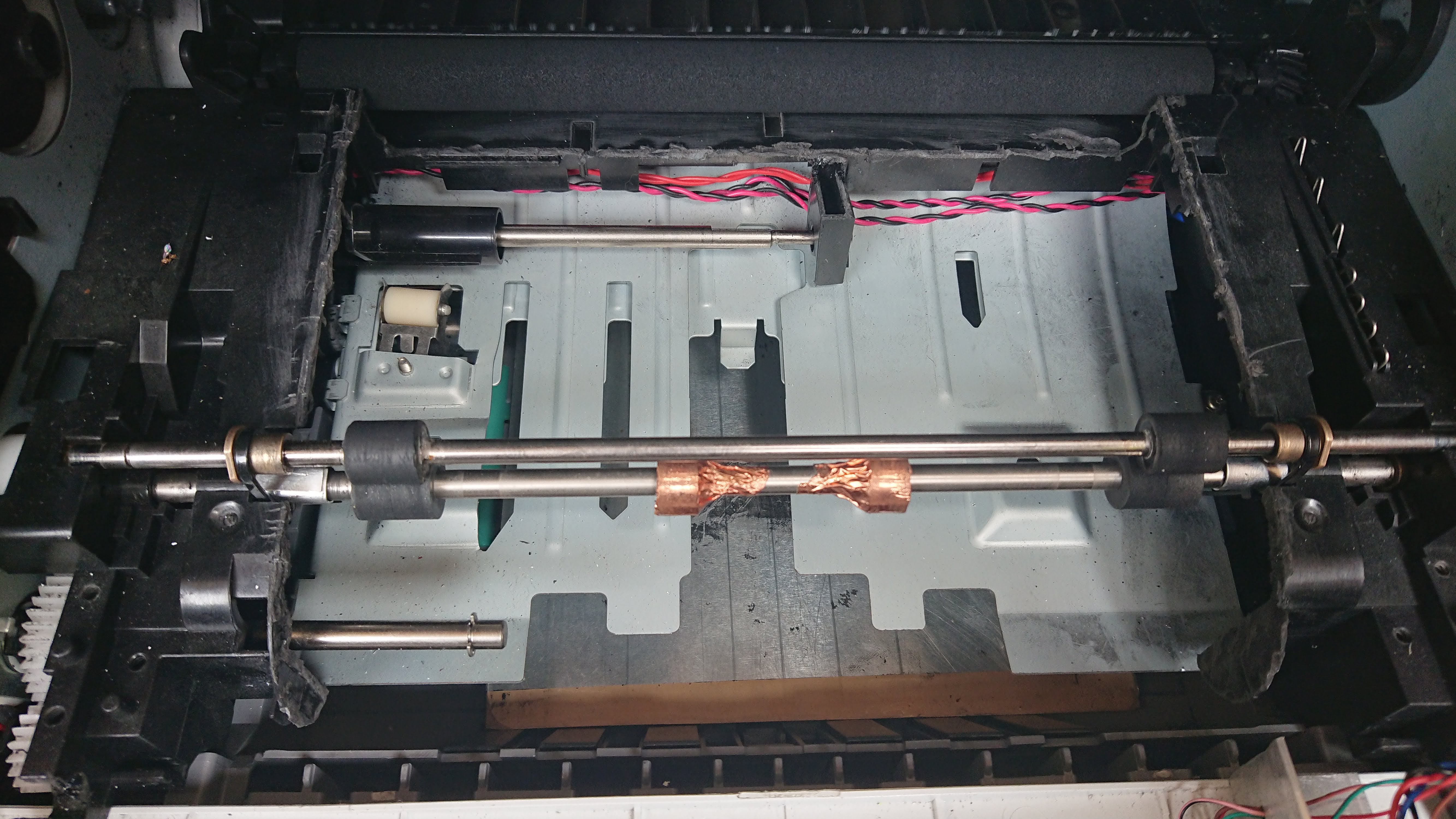
Now, you will have to cut a rectangular slice of plastic from inside the printer. Start from the entrance and go all the way up to the black roller. I used a dremel with a diamond-coated cutting disk.
There are a couple sensors in this platform, as well as the toner level sensor next to the roller. Remove and save them.
After cutting, it's time to add a second axis with rollers to press the board carrier. Mine was taken from an old dead printer, it's composed of:
- A stainless steel axis: 5mm diam, 27cm long (at least)
- 2x rubber rollers 12mm outer diam, 5mm inner diam
- 2x 8mm outer diam. brass bearing
Attach the axis to the lexmark roller using two pieces of cable tie. Move two of the lexmark rubber cylinders to the center and cover them with copper conductive tape, extending the tape upon the bare metal surface too. These cylinders will touch the carrier and ensure the board is at the right potential for toner transfer.
Hold the rubber cylinders in place using cyanoacrylate glue if required. The cylinders must be able to roll without difficulty, but don't fasten the cable ties too much as the carrier will have to fit between them.
![]()
-
3The carrier
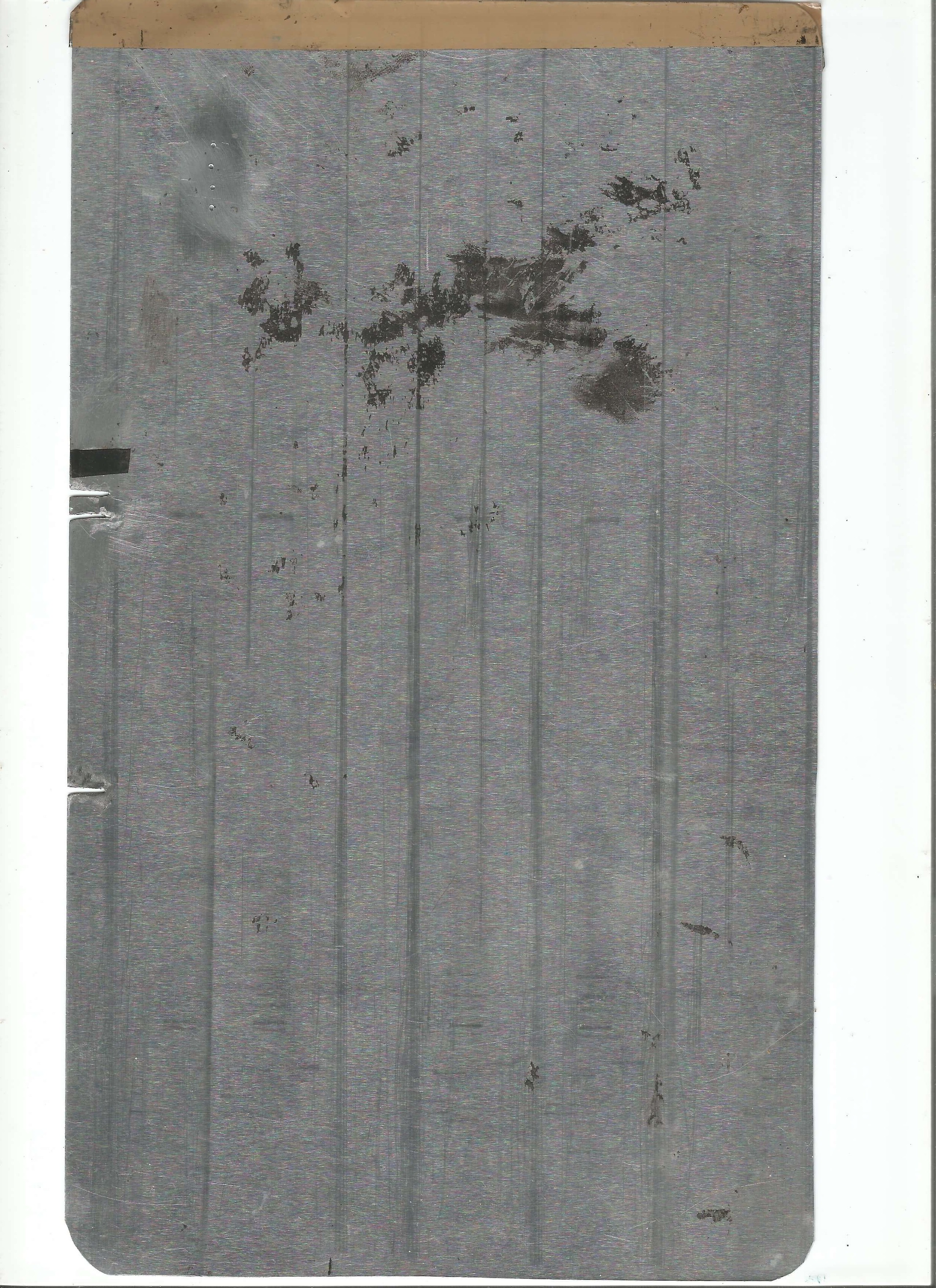
Cut a rectangular piece of the aluminum sheet about 17.5cm wide and 29cm long. That's going to be our carrier. On the front edge, bend a strip of tape, so that it sticks evenly on both top and bottom sides. The tape makes sure the carrier goes in gently and does not scrath the photosensitive printer drum.
Shown in the picture is the back finished carrier. Don't drill any hole or make any cut just yet.
![]()
-
4The carrier guide
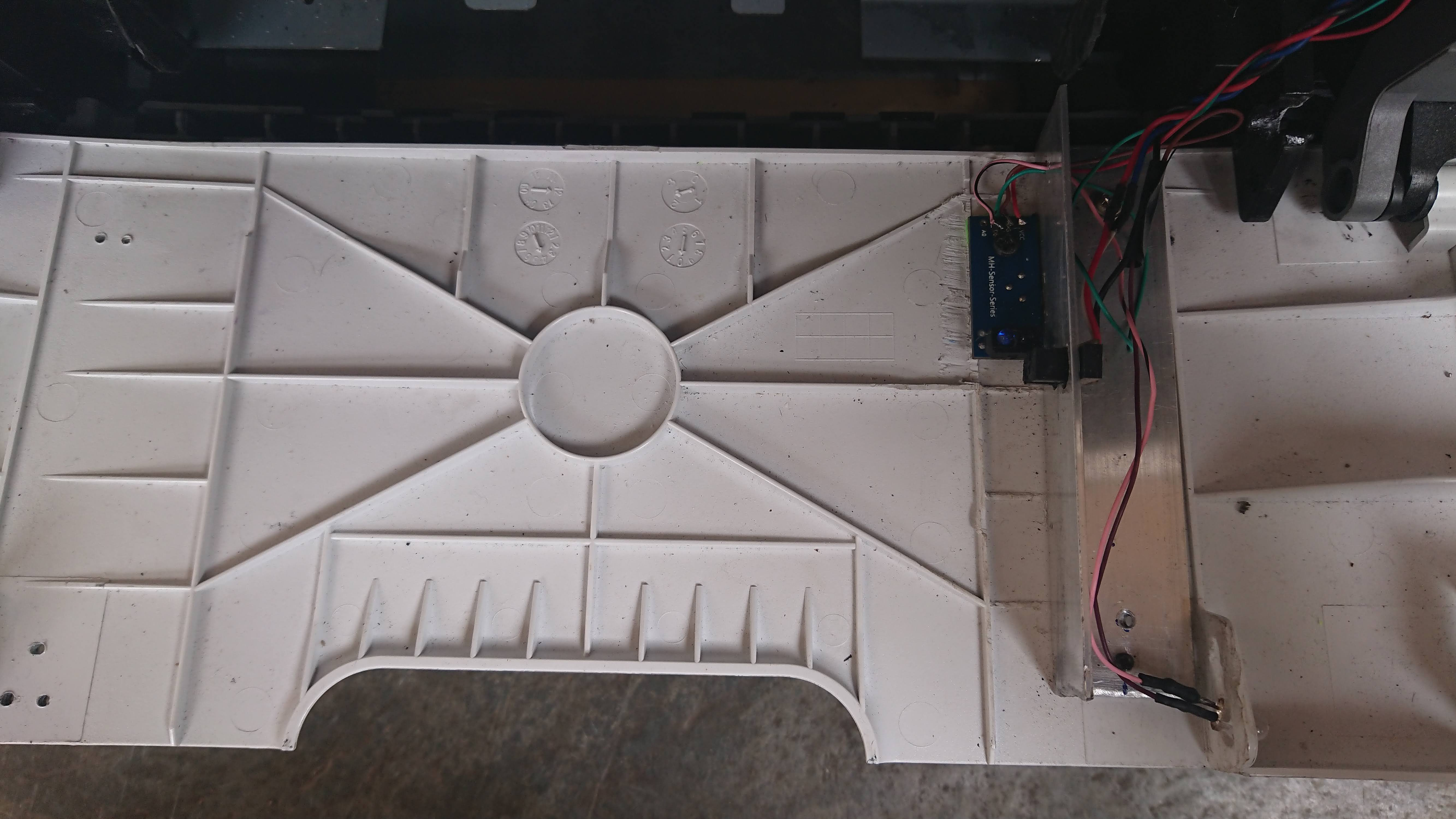
Cut a 10.5cm piece of the 1"x1" aluminum angle and align it to the preexistent marks on the external foldable cover. Trim its length so that you can still fold back the cover (that's merely a convenience, though).
Insert the carrier manually between the rollers that we just finished, and try to make sure the angle matches its right side.
Once you've found the best position, drill two holes near the edges of the angle and fix it on the cover with two screws.
![]()
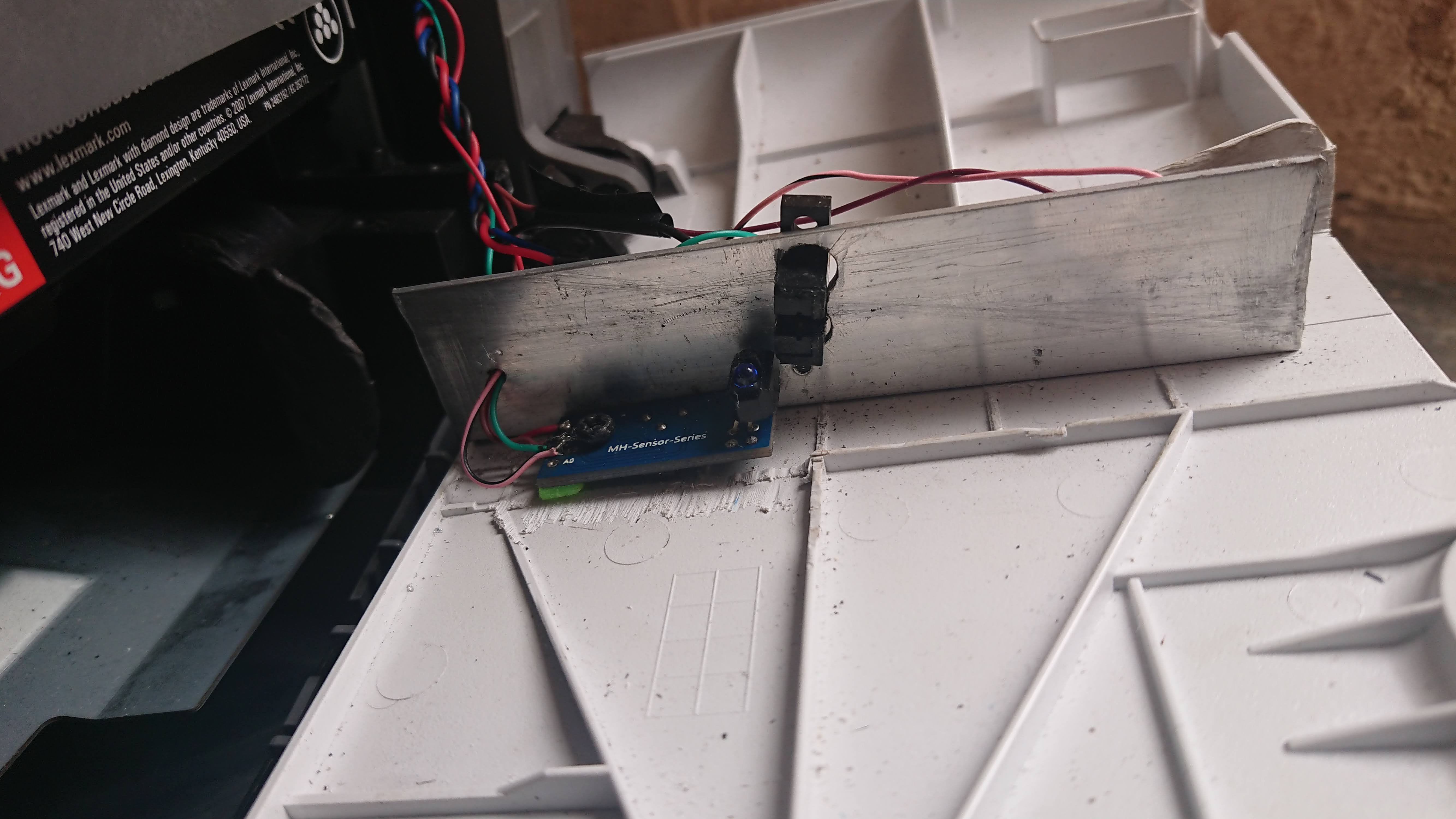
Now grab the fuser exit sensor and remove the spring and its support structure. This will be your New Paper In Sensor or NPIS.
With a pencil, mark the angle at which the right side of the carrier touches the aluminum angle. This will be the NPIS centerline.
About 10.6cm from the paper pull axis (the one you put the rubber cylinders in), drill two 8mm diam. holes in the aluminum angle to hold the sensor, both equally spaced and perpendicular to the centerline.
Insert the NPIS in these holes and you will have something like the image below. Glue it or use a screw to keep it in place. Its 3 wires should extend all the way to the printer main board.
![]()
A small note: in the images there's also a reflexive IR sensor screwed to the bottom. I tried it so I wouldn't have to drill or cut the carrier, but the alignment this setup offered fell short of my expectations. I kept it just as an extra alignment aid, but it's not conncted to the MCU.
-
5Main board hacking
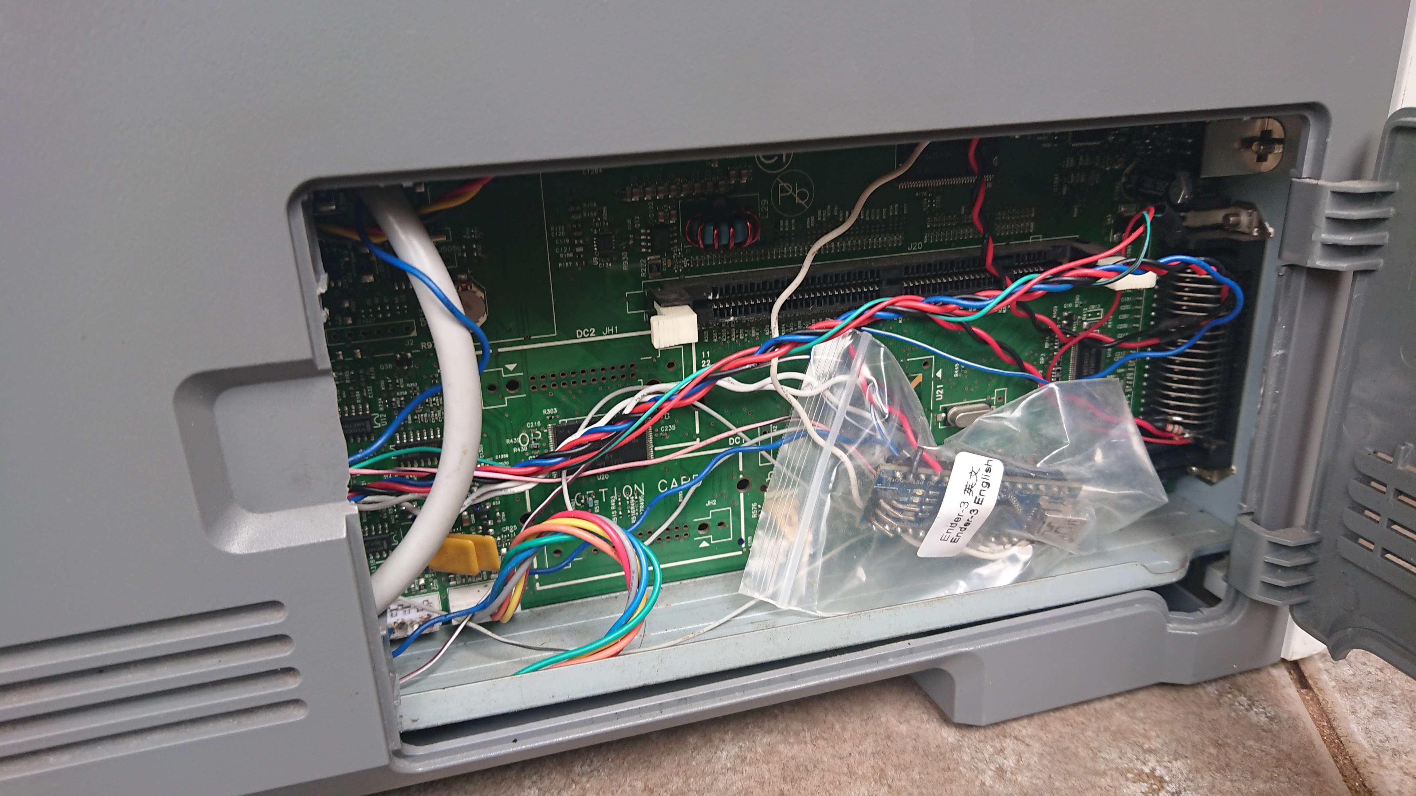
About the sensors, they are IR break-beam sensors and have 3 wires:
- Black - usually GND
- White - output. 5V idle, 0V active (active low)
- Colored - 1.1V when connect to the printer board. Probably powers the IR led.
We need to emulate the output of a 3 sensors for the printer to work:
- PPIN - Paper input sensor (J27)
- MPF - Manual paper feed (J23)
- EXIT - Paper exit (J14)
We also need to read 3 inputs:
- MPF clutch (J24) -> solder the catode of a diode to the black wire and connect it to the MCU input pin as well as to a pull-up resistor to 5V. It will swing from 24 to 0V when printer wants to pull paper.
- Operator panel (J5)
- Motor hall sensor (J17) -> we will use the blue wire. Be careful as some wires are at 24V.
And we will also use the MCU to control the paper clutch solenoid (J25) through a FET.
![]()
The comments in the code contain additional information. They also mention 3 leds. I ended up not using any, but they might be useful for debugging.
As for powering the MCU, the two lower exposed pins of the parallel port connector provide 5V. -
6Carrier marks
The hardware modification is finished.
Now, insert the carrier and mark the location for the drill or cut. In my case it was about 114.5mm from the front edge, and 4mm from the right side (for the hole).
The idea is that the cut or hole should be right before the beginning of the sensor, and the front edge should be inserted just enough to allow the rubber rollers to pull the carrier.
![]() By the way, it's a good idea to round the carrier vertices to prevent them from hitting the drum.
By the way, it's a good idea to round the carrier vertices to prevent them from hitting the drum.
That's it! You are ready to print!
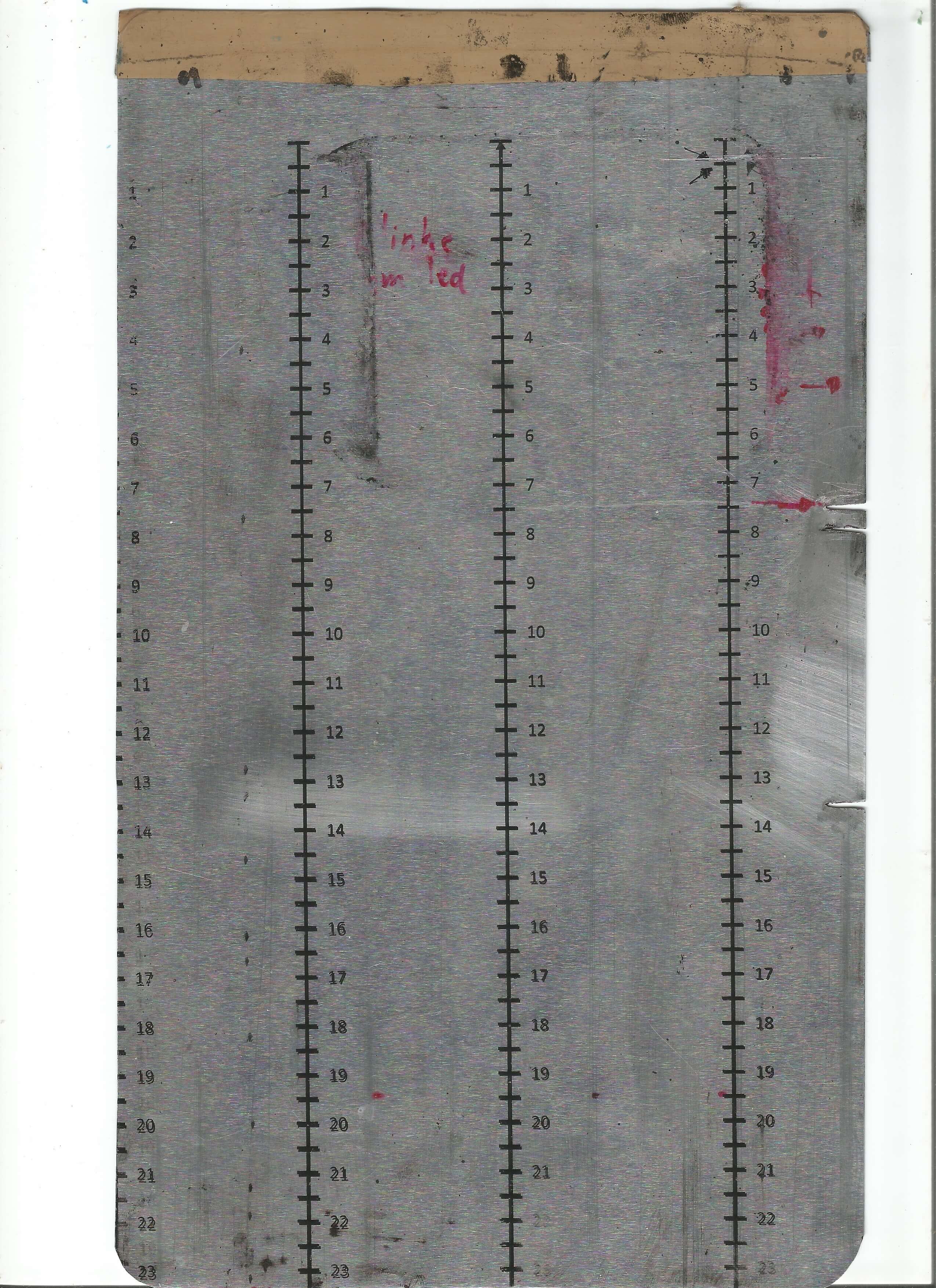
As your first test, try printing the alignment ruler in the attached PDF file. Print it in real size and leave it in a closed container with acetone for 20 min to dry. -
7Printing boards
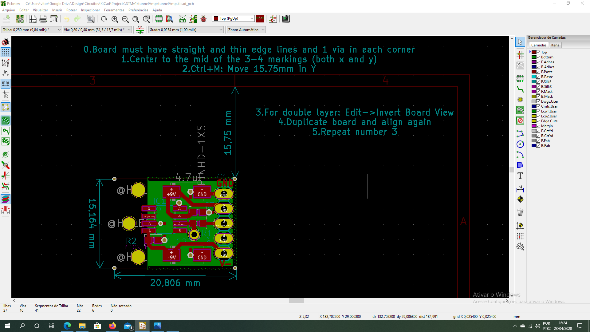
Basically, to print a PCB you have to align it in your favorite EDA software. Set page orientation to portrait and keep in mind to use the right side as a reference.
Below is a suggestion for alignment using KiCad.
![]()
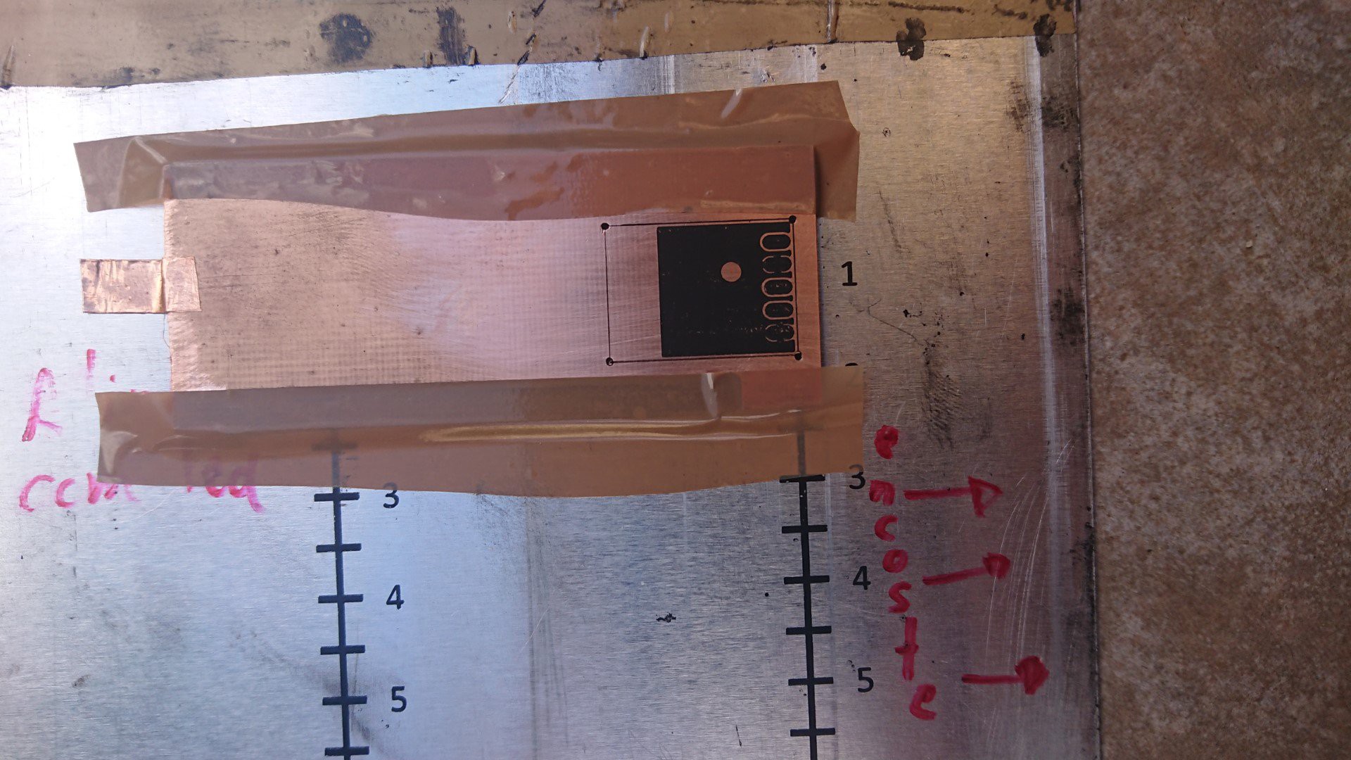
Scrap the board with steel wool, hold the heading and trailing edges of the PCB in place on top of the carrier with any thin tape and align the right edge of the PCB with the rightmost ruler line (the one you printed before).
Connect the PCB to the aluminum carrier using a piece of copper tape and clean the surface with acetone.
After printing, put the board in a closed containter with about 5ml of acetone for about 20 min to allow the toner to stick to the copper.
If you are making a double layer PCB, 15 min for the top and 20 for the bottom layer will suffice.
haxmark460 - Home PCB Printer
Direct PCB printing with a modified Lexmark e460dn laserjet printer
 Vítor Barbosa
 By the way, it's a good idea to round the carrier vertices to prevent them from hitting the drum.
Discussions
Become a Hackaday.io Member
Create an account to leave a comment. Already have an account? Log In.